HAL Id: hal-00451933
https://hal.archives-ouvertes.fr/hal-00451933
Submitted on 26 Jun 2019
HAL is a multi-disciplinary open access
archive for the deposit and dissemination of
sci-entific research documents, whether they are
pub-lished or not. The documents may come from
teaching and research institutions in France or
abroad, or from public or private research centers.
L’archive ouverte pluridisciplinaire HAL, est
destinée au dépôt et à la diffusion de documents
scientifiques de niveau recherche, publiés ou non,
émanant des établissements d’enseignement et de
recherche français ou étrangers, des laboratoires
publics ou privés.
Contribution to the Improvement of the Medical Device
SurgiScope
Sébastien Briot, Cédric Baradat, Sylvain Guegan, Vigen Arakelian
To cite this version:
Sébastien Briot, Cédric Baradat, Sylvain Guegan, Vigen Arakelian. Contribution to the Improvement
of the Medical Device SurgiScope. 2007 ASME International Design Engineering Technical
Confer-ences (DETC 2007), Sep 2007, Las Vegas, NV, United States. pp.653-661, �10.1115/DETC2007-35067�.
�hal-00451933�
CONTRIBUTION TO THE MECHANICAL BEHAVIOR IMPROVEMENT
OF THE ROBOTIC NAVIGATION DEVICE SURGISCOPE
®Sébastien Briot †, Cédric Baradat *†, Sylvain Guégan †, Vigen Arakelian †
*
«Intelligent Surgical Instruments and Systems» (ISIS) Company 20 rue du Tour de l’Eau
F-38400 Saint Martin d’Hères, France
†
Département de Génie Mécanique et Automatique, LGCGM EA3913 Institut National des Sciences Appliquées (INSA)
20 Av. des Buttes de Coësmes, CS 14315, F-35043 Rennes Cedex, France vigen.arakelyan@insa-rennes.fr
ABSTRACT
This paper proposes a new solution to the problem of torque minimization of the medical device SurgiScope® by connecting to the initial structure a secondary mechanical system, which generates a vertical constant force on the platform of the robotized device. The conditions for optimization are formulated by the minimization of the root-mean-square values of the input torques of the studied device. The positioning errors of the unbalanced and balanced robots are provided. A significant reduction of these errors is achieved by using the suggested balancing mechanism. The efficiency of the developed approach is illustrated by numerical simulations. Experimental validation of the obtained optimization is illustrated by a prototype developed in the National Institute of Applied Sciences of Rennes in collaboration with the “Intelligent Surgical Instruments & Systems” (ISIS1
) Company.
INTRODUCTION
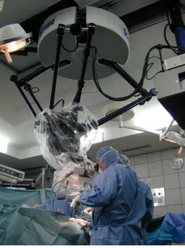
The SurgiScope® (Fig. 1) is a ceiling mounted robotized tool-holder device which belongs to the surgical navigation products family. It is developed by the ISIS company. Such a
1 ISIS: Intelligent Surgical Instruments & Systems
(http://www.isis-robotics.com).
mechanism is especially dedicated to microscope applications in neurosurgery, and allows all kinds of operations in every usual patient’s positions. The mechanical system, which carries the microscope is based on a Delta structure [1].
The Delta robot (Fig. 2) is well known in the electronics, food and pharmaceutical sectors as a reliable system with fast execution of light-duty tasks. However, in recent years, more attention has been paid to the increasing number of possible industrial applications, such as manipulation of medical devices.
In the case of the SurgiScope®, the platform with the microscope is very heavy (about 70 kg) and consequently the required input torques are increased. Moreover, with such load, the positioning errors of the platform due to elastic deformations becomes non negligible.
The compensation of the input torque is a well-known problem in the field of the mechanical engineering [2-4]. One of the methods used to solve this problem is to create a cam-spring mechanism in which the cam-spring absorbs energy from the system when torque is low, and releases energy to the system when the required torque is high. This approach is considered to be the most efficient, such that a secondary mechanism compensates exactly the load variations in the mechanical system due to the periodic torque. Such a solution is
successfully applied on the cyclic mechanisms with prescribed input motion characteristics.
FIG. 1. SURGISCOPE®, A ROBOTIZED NAVIGATION TOOL-HOLDER DESIGNED FOR NEUROSURGERY
DEVELOPED BY THE ISIS COMPANY.
FIG. 2. SCHEMATIC OF THE DELTA PARALLEL ROBOT FROM CLAVEL'S PATENT [1].
However, for many industrial systems, such as robotic systems, this solution is not applicable because a simple cam-spring mechanism cannot be adapted to the variation of the input torque due to the trajectory planning.
Another trend for the solution of this problem is the balancing of the robot mechanisms. In this case the static balancing is defined as the set of conditions under which the weight of the links of the mechanism does not produce any torque at the actuator for any configuration of the robot. This
condition is also referred to as gravity compensation. Gravity-compensated serial and parallel manipulators have been designed using counterweights, springs and sometimes cams [5-10].
However, for the complex systems, as for example the Delta parallel robot (Fig. 2), it is not easy to find any application for such a solution. The introduction of counterweights or springs brings the basic modification of the initial structure, which is constructively inefficient.
This paper proposes a new approach for the minimization of the input torques of the Delta robot. It is carried out by a secondary mechanical system, which generates a vertical force applied to the platform of the Delta robot.
The organization of the paper is as follows: first the description of the balancing mechanism is presented. Then, the detailed mathematical model for input torques minimization is formulated and an analytical solution is provided. In the next section, the influence of the balancing mechanism on the positioning errors of the platform is discussed. Finally, the prototype of the designed balancing mechanism is described and the experimental validation of the obtained optimization is presented.
DESCRIPTION OF THE BALANCING MECHANISM For the minimization of the torques of the Delta robot with 3-DOF (Fig. 2) we suggest adding a secondary mechanism between the base (1) and the platform (8). The aim of this approach is to create on the platform (8) a supplementary vertical force F, which allows the minimization of the input torques of the robot.
The designed balancing system, which has the mentioned characteristics, is based on the copying properties of the pantograph linkage (Fig. 3).
FIG. 3. COPYING PROPERTIES OF THE PANTOGRAPH LINKAGE.
The input points A and B of the pantograph are located in the horizontal and vertical guides of the rotating stand. So the suggested system has three degrees of freedom: a rotation of the stand about the vertical axis and two translations along the guides. This allows the suggested system to be passive relatively to the Delta robot when the point C is connected with the platform.
Point B is also connected with an actuator which produces a vertical force. This vertical force FB is used for the balancing
of the gravitational forces of the spatial parallel robot. It is obvious that the determination of the balancing force FB = k F
takes into account the magnification factor of the pantograph (k = AC/AB = a/b).
Thus the position of point C is represented by vector P = [x, y, z]T and the passive motions of the pantograph are represented by q = [r, , Z]T (r and Z represent the horizontal and vertical positions of point A and B, respectively, and the rotation of the pantograph around Z axis). The kinematic relations between P and q are the following: x = (1–k)rcos,
y = (1–k)rsin and z = kZ. Differentiating these equations with
respect to time, one obtains: P J q 1 (1) where
T z y x P (2)
T Z θ r q (3) k θ r k θ k θ r k θ k 0 0 0 cos ) 1 ( sin ) 1 ( 0 sin ) 1 ( cos ) 1 ( J (4)It is easy to see that a configuration singularity of the mechanism exists when x = y = 0, i.e. when the points A, B and
C are on a vertical line (Fig. 3). To execute a continuous
motion passing through such line, it may be necessary to orient the plane of the pantograph linkage relative to the Z axis. Thus, it is evident that the balancing mechanism must be equipped by a complementary rotating actuator for its orientation in the case of singular trajectories. This complementary actuator may be in operation only for special cases.
FIG. 4. DELTA ROBOT WITH THE BALANCING MECHANISM.
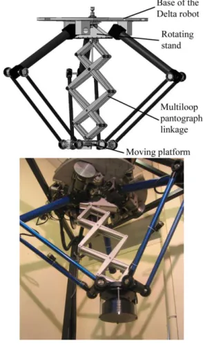
Fig. 4 shows the balancing mechanism, which is implemented in the structure of the Delta robot. Multiloop pantograph linkage with several link lengths allows the
reduction of the overall size of the balancing mechanism. The sizes of the pantograph links must be chosen in such a manner that they should not collide with the legs of the Delta robot.
The next part will deal with the input torques compensation of the Delta robot.
INPUT TORQUES MINIMIZATION
In neurosurgery applications, the Delta robot is used in static mode operation. Thus, the input torque of the nth actuator can be expressed as:
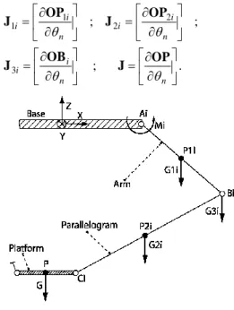
n n n n n M M M M M 1 2 3 4 (5) where M1n is the torque due to the gravitational forces of the
arms (see Fig. 5), M2n is the torque due to the parallelograms,
M3n is the torque due to the joints on points Bi, M4n is the torque
due to the gravitational forces of the platform and medical device. For i, n =1, 2, 3 and j =1, 2, 3 Mjn is equal to:
n i ji T ji jn x y z x y z M
3 1 ) , , ( ) , , ( J G (6)and for n = 1, 2, 3 and j = 4, Μst4n is equal to:
nT
n x y z x y z
M4 ( , , ) J ( , , )G (7) where J1i is the Jacobian matrix between the point P1i and the
actuated variables n, J2i is the Jacobian matrix between the
point P2i and the actuated variablesn, J3i is the Jacobian matrix
between the point Bi and the actuated variablesn, J is the
general Jacobian matrix of the robot, between the point P and the actuated variables n for i, n = 1, 2, 3, and G and Gji are the
gravity forces (Fig. 5). The matrix Jji (j = 1, 2, 3) can be written
as: . ; ; ; 3 2 2 1 1 n n i i n i i n i i OP J OB J OP J OP J (8)
FIG. 5. GRAVITY FORCES FOR THE LEG i. It should be noted that the Delta robot used in the medical device SurgiScope® is symmetrical and the values of the input
torques for the actuators are also symmetrical with altered zones (rotations of ±120°). Thus, in the following numerical illustrations we will only present the input torque for one actuator.
The three input torques can be presented in function of force F by the following expression:
F M M M M M M T bal bal bal 0 0 3 2 1 3 2 1 J (9)
where Mibal is the input torque of actuator i after balancing (i =
1, 2, 3).
The condition for the minimization of the root-mean-square (RMS) value of the torques can be expressed as:
F N p i p p p i p p p i N F z y x J z y x M min ) , , ( ) , , ( 1 3 1 2 ) 3 (
(10)where Mi is the initial torque of the actuator i, N is the number
of calculated positions of the robot, J(3i) is the i th
column of the third line of the matrix J, i = 1, 2, 3 is the number of the actuator and xp, yp, zp are the coordinates of the pth calculated
position of the workspace.
For the minimization of the RMS value of the torques, it is necessary to minimize the sum:
N k i p p p i p p p i x y z J x y z F M 1 3 1 2 ) 3 ( ( , , ) ) , , ( (11)For this purpose, we shall achieve the condition:
0 /
F , from which we determine the force:
N k i p p p i N k i p p p i p p p i z y x J z y x M z y x J F 1 3 1 2 ) 3 ( 1 3 1 ) 3 ( ) , , ( ) , , ( ) , , ( (12)Numerical simulation. For the Delta robot of the SurgiScope®, the parameters are the following (see Fig. 5): - lAiBi=0,75 m;
- lBiCi = 0,95 m;
- m1i = 2,3 kg (mass of ith arm with center P1i);
- m2i = 5,2 kg (mass of ith parallelogram with center P2i);
- m3i = 3,1 kg (mass of the joint at point Bi);
- m = 79 kg (mass of the platform, joints and medical device, with center in the point P);
- lAiP1i = lAiBi/2 = 0,375 m;
- lBiP2i = lBiCi/2 = 0,475 m.
Thus the value of the added force for the given parameters is F = 931 N.
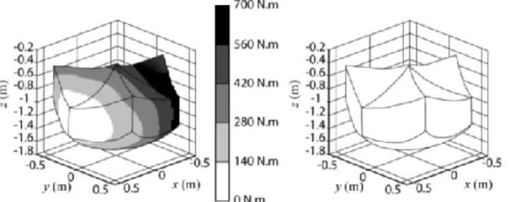
FIG. 6. ABSOLUTE VALUE OF INPUT TORQUE 1 FOR UNBALANCED (LEFT) AND BALANCED (RIGHT) DELTA
ROBOT.
Fig. 6 shows the variations of the input torques for unbalanced and balanced Delta robot. Thus, the reduction of the RMS value of the input torque is 99.5 %. The reduction of the maximum value of the torque is 92%.
It should be noted that the torques can also be minimized by the application of a variable force [11]. However, the numerical simulations showed that in this way non significant improvement can be achieved (about 1%). Thus, for the minimization of the input torques of the medical device SurgiScope®, it is better to use a constant force taking into account that it is much easier to create than a variable force.
IMPROVEMENT OF THE POSITIONING ACCURACY It should be noted that most research papers devoted to the study of parallel manipulators deal with the mechanical structures with rigid links. So in this case, the position of the platform is considered to be perfectly parallel to the base and its coordinates are determined from the nominal values of the link lengths. But in reality, the elastic deformations of the mechanical structure of the manipulator change the position and orientation of the platform. Our observation showed that the increase of the payload leads to increase in these errors.
In this section, it is shown that the suggested balancing mechanism has a good influence on the improvement of the positioning accuracy of the parallel robot Delta.
Influence of the balancing mechanism on the positioning errors.
Static rigidity of the Delta robot is defined as the 66 symmetrical matrix K that maps generalized infinitesimal displacements of the platform X = [x, y, y, x, y, z]T
to generalized external loads F = [Fx, Fy, Fz, Mx, My, Mz]T.
Thus, we have
X K
F . (13)
TABLE 1. LINKS PARAMETERS.
Link 4 (Fig.2) Link 5 (Fig.2) Cross-section area (m²) 1.12410-3 1.77310-4
Quadratic moment about y (m4) 7.91310-7 2.1310-8 Quadratic moment about z (m4) 7.91310-7 2.1310-8
Elastic modulus (E) (GPa) 70 70 Poisson coefficient (υ) 0.346 0.346
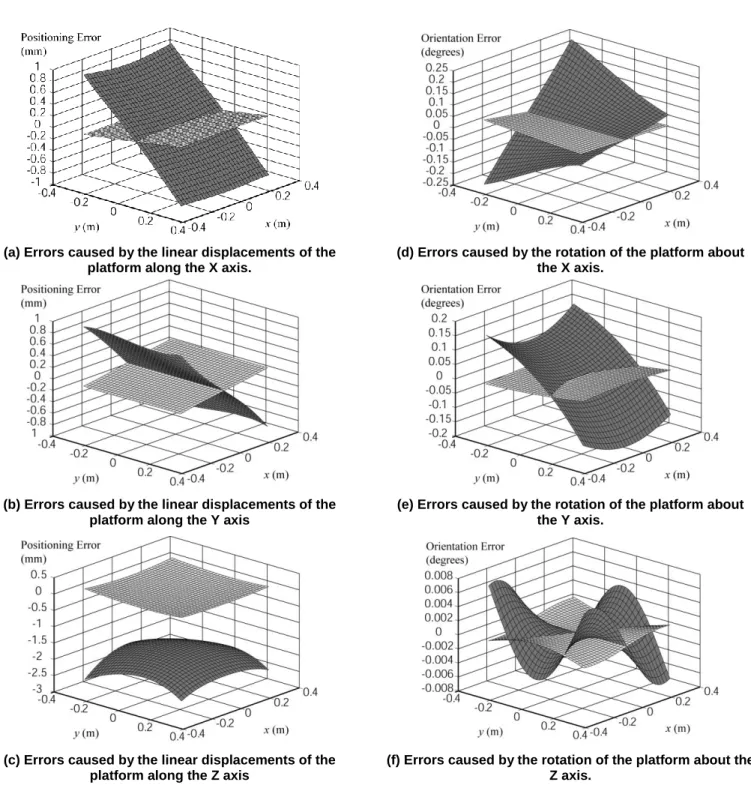
(a) Errors caused by the linear displacements of the platform along the X axis.
(d) Errors caused by the rotation of the platform about the X axis.
(b) Errors caused by the linear displacements of the platform along the Y axis
(e) Errors caused by the rotation of the platform about the Y axis.
(c) Errors caused by the linear displacements of the platform along the Z axis
(f) Errors caused by the rotation of the platform about the Z axis.
FIG. 7. ERRORS CAUSED BY THE LINEAR DISPLACEMENTS AND THE ROTATION OF THE PLATFORM DUE TO THE ELASTICITY OF LINKS FOR UNBALANCED (DARK GRAY) AND BALANCED (LIGHT GRAY) DELTA ROBOT CALCULATED
FOR THE ALTITUDE z = -1 m. With the link parameters given in table 1 and the payload
equal to 70 kg, the positioning errors caused by the elastic deformation of the robot structure is represented in Fig. 7 (dark gray). When the balancing force (Fbal = 931 N) is applied on the
platform, the relationship Eq. (13) can be rewritten as:
bal bal F KΔX
F (14)
where Fbal = [0, 0, Fbal, 0, 0, 0]T.
Fig. 7 shows the positioning errors caused by the elastic deformation of the robot structure with balancing mechanism (light gray).
Table 2 shows a comparative analysis of the maximum values of the positioning errors along the corresponding axis for the two cases. The reduction in the positioning and orientation errors is significant (from 86.8% to 97.5%).
TABLE 2. MAXIMAL ABSOLUTE POSITIONING AND ORIENTATION ERRORS FOR UNBALANCED AND BALANCED ROBOTS. Constant balancing force
(Fbal = 931 N) Maximal absolute positioning errors Position (mm) Orientation (10-3 rad.) x y z x y z Unbalanced robot 0.92 0.923 2.636 4.35 3.37 0.13 Balanced robot 0.109 0.107 0.065 0.41 0.31 0.02 Gain % 88.2 88.4 97.5 90.6 90.8 86.8
Thus, it was shown that the balancing mechanism allows improving the positioning accuracy of the Delta robot. However, it is also interesting to study the following problem: to find such a force F, which allows carrying out the best improvement of the positioning errors.
Let us consider this problem. Eq. (14) can be rewritten as:
bal bal ΔX ΔX F
S (15)
where S = K-1
The condition for minimizing the errors on the position is:
F N p p g bal p p g bal p p g bal p z F S y F S x F S min 1 2 33 2 23 2 13
(16) what leads to :
N p p p p N p p g p p g p p g p bal S S S z S y S x S F 1 2 33 2 23 2 13 1 33 23 13 (17) whereS
ijp, xgp, p g y and zgpare respectively the values of Sij,
xg, yg and zg of the pth calculated point of the workspace.
TABLE 3. MAXIMAL ABSOLUTE POSITIONING AND ORIENTATION ERRORS FOR BEST POSITIONING IMPROVEMENT. Constant balancing force
(Fbal = 924 N) Maximal absolute positioning errors Position (mm) Orientation (10-3 rad.) x y z x y z Unbalanced robot 0.92 0.923 2.636 4.35 3.37 0.13 Balanced robot 0.102 0.099 0.077 0.37 0.29 0.01 Gain % 88.9 89.3 97 91.5 91.4 92.3
The obtained force, determined from Eq. (17), is Fbal = 924
N. The calculated errors are given in table 3. The comparative analysis shows that the obtained reduction of the deformations is not significant. This can be explained by the small difference between the applied forces (the difference is 7 N).
Thus, it should be noted that, by reduction of the input torques of the Delta robot, a quasi best improvement of its positioning accuracy is also achieved.
In the next section we present the developed prototype and the experimental validation of numerical simulations.
PROTOTYPE AND EXPERIMENTAL VALIDATION A prototype has been designed and built for validation of the obtained results. It was implemented in the structure of the Delta robot of the SurgiScope® provided by the I.S.I.S Company. To design the prototype, it was firstly necessary to find the optimal lengths of the multiloop pantograph linkage taking into account that it should not collide with the legs of the Delta robot. Then, the right stiffness characteristics of the links were found by evolution of the shapes and design concept of rods, as well as by successive optimization based on the finite element analysis.
FIG. 8. CAD MODEL AND PROTOTYPE OF THE BALANCING MECHANISM IMPLEMENTED IN THE
After assembling the prototype, its static balancing was readily verified and the force for the balance of the developed multiloop pantograph linkage was found through experimentation (FB/PANTOGRAPH = 52 N). The base of the
balancing mechanism was then suspended from the fixed structure of the Delta robot and its end was connected to the moving platform (Fig. 8). In order to create a balancing force, a counterweight was used. It is obvious that for industrial applications, better design solutions could be found, as pneumatic cylinder or electric actuator with constant moment. However, the validation of the obtained results can also be achieved by a counterweight, which develops the same force as a pneumatic cylinder or electric actuator.
Experimental results and comparative analysis We have observed the torque response of the system to a quasistatic movement composed of a straight line with respect to Z axis and a circle in the space (Fig. 9).
FIG. 9. SELECTED TRAJECTORY FOR EXPERIMENTAL VALIDATION OF TORQUE MINIMIZATION.
The input torques measured for each actuator in different cases are denoted by A, B, C and D:
A. unloaded robot;
B. loaded robot (robot with the load of 690 N);
C. load balanced robot (balancing by mechanism with force of 690 N);
D. load and mechanical system balanced robot (balancing by mechanism with force of 880 N).
We would like to draw attention to cases C and D. In case C, we have only compensated the load added on the robot platform, to obtain the same result as thus obtained when the robot is unloaded. In case D, we have taken into account the mass of the Delta robot links, which gives the best result.
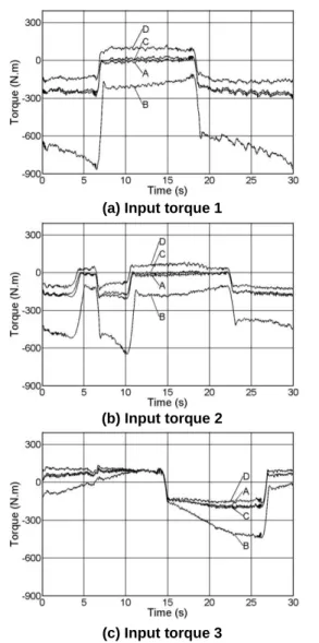
The obtained measures confirm perfectly the theoretical results (Fig. 10):
- when balancing is carried out by taking into account only the load on the platform, the result are similar to those obtained for the unloaded robot (cases A and C).
- when balancing is carried out by taking into account the load on the platform and loads of robot links, we obtain the lowest values for the input torques (cases D).
Table 4 shows the reduction of the input torques.
(a) Input torque 1
(b) Input torque 2
(c) Input torque 3
FIG. 10. EXPERIMENTAL MEASURES OF INPUT TORQUES FOR THE THREE ACTUATORS OF THE DELTA
ROBOT.
TABLE 4. INPUT TORQUES. Maximum values of the measured torques
(N.m)
Actuator 1 Actuator 2 Actuator 3
A 306 217 211 B 882 653 449 C 324 208 221 D 199 145 180 Improvement gain 2 (%) C 63 67 50 D 77 77 59
We can observe that improvement for actuators 1 and 2 in the quasistatic movement is 77% and for actuator 3 is 59%.
2
This gain represents in percent the reduction of the torques compared to the case B.
Gains for actuator 3 are quite different from the two others, because this one was less solicited by the given trajectory than the two other, i.e. for the given trajectory the load of the platform on actuator 3 was smaller. So, it is natural that for this actuator we do not observe consequent improvement of its torque by the balancing mechanism.
The experimental validation of the suggested balancing approach showed that satisfactory results are achieved and the developed system is fully operational.
The next step of the experimental validation is the estimation of the positioning errors for balanced and unbalanced robots. For this purpose a trajectory given by the following 9 points was chosen (table 5).
TABLE 5. TRAJECTORY FOR EXPERIMENTAL VALIDATION OF THE POSITIONING ACCURACY IMPROVEMENT. Points x (mm) y (mm) z (mm) 1 400.0 0.0 -900.0 2 325.5 41.7 -949.9 3 249.9 84.4 -1000.2 4 175.6 127.5 -1050.0 5 100.3 169.9 -1100.1 6 25.5 212.4 -1149.8 7 -49.9 255.4 -1199.7 8 -124.8 298.3 -1249.6 9 -200.8 340.7 -1299.8
These points are uniformly distributed about a straight line of 800 mm length. To obtain this line physically, a sphere is used, which was moved along a rail (Fig. 11). The position of each point is measured by three dial gauges, which determine the centre of the sphere. The purpose of these measurements is to obtain the positioning errors for unbalanced and balanced Delta robots.
FIG. 11. MEASURING OF THE POSITIONING ERRORS FOR GIVEN STRAIGHT LINE TRAJECTORY.
FIG. 12. RELATIVE POSITIONING ERRORS WITH RESPECT TO Z AXIS FOR UNBALANCED AND BALANCED
ROBOTS.
The obtained results are shown in Fig. 12. The abscissa axis corresponds to the unloaded case. Then the Delta robot was loaded and the relative errors were measured (graph “unbalanced robot”). Finally the robot was balanced by the suggested mechanism and relative errors are shown for the “balanced robot”. The average rate of the improvement of the relative positioning accuracy with respect to the vertical axis is 93.5%, which corresponds to the value obtained by the numerical simulations.
CONCLUSION
The paper provided a new study concerning the mechanical behavior improvement of the medical device SurgiScope®. The aim of this study is the minimization of input torques of the Delta robot used for robotic navigation of the medical device SurgiScope®. For this purpose a new approach for balancing of Delta robot has been developed. It involves connecting a secondary mechanical system to the initial robot, which generates a vertical force applied to the platform of the robot. The suggested balancing mechanism is designed on the base of the multiloop pantograph linkage introduced between the robot base and the platform.
It was shown, by simulation and confirmed by experimental study, that a significant reduction of input torques can be achieved by using the suggested balancing mechanism: the reduction of the root-mean-square value of the input torques due to the gravitational forces is 99.5%. Moreover, a significant reduction of the positioning errors is achieved by using the balancing mechanism (from 86.8% to 97.5%).
It should be noted that the suggested balancing mechanism not only improves the positioning accuracy of the parallel robot, but also sharply reduces stress in its links and efforts in the joints. This system can also be used for operational safety of robotized medical devices SurgiScope® because it can maintain the fixed position of the platform if the parallel robot actuators should accidentally stop.
Finally, it should be noted that the designed balancing mechanism has been patented [12] and additional information is available upon request.
ACKNOWLEDGMENTS
The authors thank the “Intelligent Surgical Instruments and Systems” Company for its financial support and Professor Jean Le Flecher for the advice during development of the prototype.
REFERENCES
[1] Clavel, R., 1990, “Device for movement and displacing of an element in space,” US Patent n° 4976582, date of patent: December 11.
[2] Angeles, J., and Wu, C.-J., 2001, “The optimum synthesis of an elastic torque-compensating cam mechanism,” Mechanism and Machine Theory, 36, pp.245-259.
[3] Nishioka, M., 1999, “Design of torque compensation cam using measured torque distribution,” Proceedings of the 10th World Congress on the Theory of Machines and Mechanisms, vol.4, 20-24 June, Oulu, Finland, pp.1471-1476.
[4] Guilan, T., Haibo, F., and Weiyi, Z., 1999, “A new method of torque compensation for high speed indexing cam mechanisms,” ASME Journal of Mechanical Design, 121, pp.319-323.
[5] Arakelian, V. and Smith, M.R., 2005, “Shaking force and shaking moment balancing of mechanisms: an historical review with new examples,” J. Mech. Design Trans. ASME, 127, March, pp. 334-339 (see also ERRATUM, Vol. 127, September 2005, pp. 1034-1035)
[6] Fattah, A. and Agrawal, S. K., 2006, “Gravity-balancing of classes of industrial robots”, Proceedings of the 2006 IEEE International Conference on Robotics and Automation, Orlando, Florida – May 2006, pp. 2872-2877.
[7] Arakelian, V., 1998, “Balancing of hand-operated manipulators”, Journal of Mechanism and Machine Theory, 33 (4), pp. 437 – 442.
[8] Arakelian, V., 1991, “Balanced manipulator,” Patent SU n°1673432, date of patent: August 30.
[9] Wang, J., and Gosselin, C., 2000, “Static balancing of spatial four-degree-of-freedom parallel mechanisms,” Mechanism and machine theory, 35, pp.563-592.
[10] Ebert-Uphoff, I., Gosselin, C., and Laliberte, T., 2000, “Static balancing of spatial parallel platform mechanisms,” - Revisited, TransASME, Journal of Mechanical Design, 122, pp.43-51.
[11] Baradat, C., Arakelian, V. and Briot, S., 2005, “Design of a torque-minimizing mechanism for the Delta parallel robot,” Proceedings of the 20th Canadian Congress of Applied Mechanics: CANCAM 2005, McGill University, May 30th to June 2nd, pp. 413-414.
[12] Baradat, C., Arakelian, V., and Maurine, P., 2006, “Parallel robot including of load-compensation system”, Patent FR2880575, July 14.