HAL Id: hal-00309013
https://hal.archives-ouvertes.fr/hal-00309013
Submitted on 5 Aug 2008
HAL is a multi-disciplinary open access
archive for the deposit and dissemination of
sci-entific research documents, whether they are
pub-lished or not. The documents may come from
teaching and research institutions in France or
abroad, or from public or private research centers.
L’archive ouverte pluridisciplinaire HAL, est
destinée au dépôt et à la diffusion de documents
scientifiques de niveau recherche, publiés ou non,
émanant des établissements d’enseignement et de
recherche français ou étrangers, des laboratoires
publics ou privés.
CT-PET Landmark-based Lung Registration Using a
Dynamic Breathing Model
Sylvie Chambon, Antonio Moreno, Anand Santhanam, Jannick Rolland, Elsa
Angelini, Isabelle Bloch
To cite this version:
Sylvie Chambon, Antonio Moreno, Anand Santhanam, Jannick Rolland, Elsa Angelini, et al..
CT-PET Landmark-based Lung Registration Using a Dynamic Breathing Model. International Conference
on Image Analysis and Processing ICIAP 2007, Sep 2007, Modena, Italy. pp.691-696. �hal-00309013�
CT-PET Landmark-based Lung Registration Using a Dynamic Breathing Model
S. Chambon
1, A. Moreno
1, A. P. Santhanam
2,3, J. P. Rolland
2, E. Angelini
1, I. Bloch
1 1ENST, GET - T´el´ecom Paris, CNRS UMR 5141 LTCI - Paris, France
2ODALab, University of Central Florida,USA
3Department of Radiation Oncology, MD Anderson Cancer Center Orlando, USA
{Sylvie.Chambon,Antonio.Moreno,Elsa.Angelini,Isabelle.Bloch}@enst.fr , {anand,jannick}@odalab.ucf.edu
Abstract
This paper deals with the problem of non-linear landmark-based registration of CT (at two different instants of the breathing cycle, intermediate expirations) and PET images of thoracic regions. We propose a general method to introduce a breathing model in a registration procedure in order to simulate the instant in the breathing cycle most similar to the PET image and guarantee physiologically plausible deformations. Initial results are very promising and demonstrate the interest of this method to improve the combination of anatomical and functional images for diag-nosis and oncology applications.
1. Introduction
Registration of multimodal medical images is a widely addressed topic and is important in many different domains, in particular for oncology and radiotherapy applications. We consider Computed Tomography (CT) and Positron Emission Tomography (PET) of thoracic regions, which provide complementary information about the anatomy and the metabolism of the human body (see Figure 1). Their registration has a significant impact on improving medical decisions for diagnosis and therapy [7, 14, 23]. Linear regis-tration is not sufficient to cope with the local deformations produced by cardiac and respiratory motions. Therefore, non-linear registration methods are required to register mul-timodality images of thoracic and abdominal regions, even with combined PET/CT scanners [21].
Most of the existing non-linear registration methods use intensity information or features in order to calculate the transformation between the images [8, 13, 26]. Thus they have to either find the transformation that maximizes the similarity between the registered image and the target image (iconic methods) or compute a transformation that matches some particular features (landmarks) in both images (geo-metrical methods). In the case of landmark-based meth-ods, the selection of these particular features is an important task. In many methods, the curvature of the surfaces to
reg-ister is used. However, few papers included a detailed study of the selection of the landmarks [3, 16]. Moreover, most registration methods are based on image information, and do not take into account the physiology of the human body. However, physiological information can be useful in order to ensure realistic deformations and to guide the registra-tion process. While several papers present breathing models built for medical visualization [27], no paper exploits such a model in a registration process. Consequently, in this paper, we propose an approach in which we integrate a physio-logically driven breathing model in a non-linear registration procedure based on lung surface landmark points in order to guarantee physiologically plausible deformations.
In Section 2, we summarize existing works which use breathing models combined (or not) with registration al-gorithms and then we provide an overview of the selected model. The proposed model-based non-linear registration algorithm is detailed in Section 3. Then, the application of a landmark-based registration method adapted to patholog-ical cases combined with the breathing model is described in Section 4. Section 5 discusses some results.
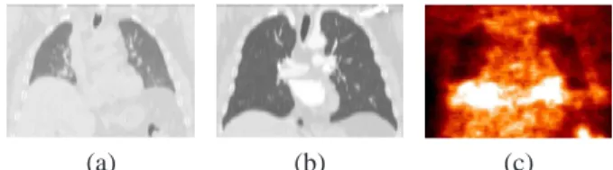
(a) (b) (c)
Figure 1. Corresponding views of the same patient in CT
(a)–(b) for two instants of the breathing cycle, and PET (c).
2
Breathing Models
2.1
Thoracic Imaging Registration
A recent study highlighted the effects of breathing dur-ing a non-rigid registration process and the importance of taking these into account [22]. Three techniques for respiration-gated radiotherapy are being developed to im-prove the efficiency of lung tumors radiations:
(1) active: controling the patient’s breathing via airflow blockage;
(2) passive or empirical: using external measurements in order to adapt radiation protocols to the tumor’s mo-tion [9, 12, 25];
(3) model-based: employing a breathing model to predict lungs deformations during the breathing cycle [19]. We focus on thoracic volume registration and propose a “patient-specific” registration through the use of a breath-ing model (technique (3)). Different bio-mathematical rep-resentations of the human respiratory mechanics have been developed [10]. Mathematical tools can be employed and the most popular technique, for medical visualization, is called NCAT (NURBS-based cardiac-torso). It is based on Non-Uniform Rational B-Spline (NURBS) to correct for respiratory artifacts of SPECT images [20]. A multi-resolution registration for 4D Magnetic Resonance Imaging (MRI) was proposed in [15]. In [5], a 4D NCAT phan-tom and a 3D CT image were used to generate 4D CT and to compute an elastic registration. Physically-based
models describe the important role of airflow inside the
lungs and can be based on Active Breathing Coordinator (ABC) [19] or volume preservation relation [17, 27]. Au-thors of [15, 22] used pre-register MRI to estimate the breathing model. In [5], the NCAT phantom was used, but, from a modeling and simulation point of view, physically-based deformation methods are better adapted for simulat-ing lung dynamics as they allow precise generation of inter-mediate 3D lung shapes. They are easy to adapt to patients, without the need for physical external adaptations for each radiotherapy treatment.
2.2
Physics-Based Breathing Model
The modeling approach used in this work was previously discussed in [17] and the two major components involved in the modeling and visualization efforts include:
(1) the parameterization of Pressure-Volume (PV) data of a human subject which act as an ABC;
(2) the estimation of the deformation operator from either 4D (3D+t) CT lung data or two 3D CT lung data set. In step (1) a parameterized PV curve, obtained from nor-mal human subjects, is used as a driver for simulating the 3D lung shapes at different lung volumes. In step (2), the computation takes as inputs the nodal displacements of the 3D lung model and the estimated amount of force applied on the nodes of the meshes (which are on the surface). Dis-placements are obtained from 4D CT of a normal human subject. The direction and magnitude of the lung surface point’s displacement are computed using the fact that the expansion of lung tissues is linearly related to the increase in lung volume. The estimated amount of applied force on each node (that represents the air-flow inside lungs) is esti-mated based on a PV curve and the lungs’s orientation with respect to the gravity, which controls the air flow. Given
these inputs, a physics-based deformation approach based on Green’s function (GF) formulation is estimated to de-form the 3D lung surface models. Specifically the GF is defined in terms of a physiological factor, the regional alve-olar expandability (elastic properties), and a structural fac-tor, the inter-nodal distance of the 3D surface lung model. To compute the coefficients of these two factors, an iterative approach is employed and, at each step, the force applied on a node is shared with its neighboring nodes based on a lo-cal normalization of the alveolar expandability coupled with inter-nodal distance. The process stops when sharing of the applied force reaches equilibrium [18].
3
Using the Breathing Model in Registration
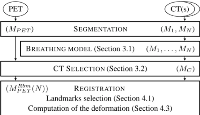
We have conceived an original algorithm in order to in-troduce the advantages of using the breathing model de-scribed above in a registration procedure. Figure 2 shows the computational workflow of the complete algorithm. The inputs consist of one PET volume and two CT volumes of the same patient, corresponding to two different instants of the breathing cycle (intermediate expirations). The first step of the algorithm consists in segmenting the lungs and the tu-mors on the PET data and on the two CT data sets, using a robust mathematical-morphology-based approach [4]. The meshes (called CT mesh and PET mesh) corresponding to the different segmentation results are computed. The sub-sequent steps are detailed next.
PET CT(s)
SEGMENTATION (M1, MN)
BREATHING MODEL(Section 3.1) CT SELECTION(Section 3.2)
REGISTRATION
Landmarks selection (Section 4.1) Computation of the deformation (Section 4.3)
(M1, . . . , MN)
(MC)
(MRbm P ET(N ))
(MP ET)
Figure 2. Computational workflow of the registration of CT
and PET images using a breathing model (cf. Section 3.3).
3.1
Patient-Specific Breathing Model
We first estimate the intermediate 3D lung shapes be-tween the two segmented CT lung datasets. Displacements of lung surface points are computed as follows:
(1) Directions are given by the model (computed from a 4D CT normal data set of reference).
(2) Magnitudes are “patient-specific” and are computed from the given 3D CT lung datasets.
In other words, for known directions of displacement the magnitude of the displacement is computed from the two 3D CT lung datasets. With known estimations of applied
force and “subject-specific” displacements the coefficients of the GF can be estimated (cf. Section 2.2). Then, the GF operator is used to compute the 3D lung shapes at differ-ent intermediate lung volumes. This methodology is further detailed in [17].
3.2
CT Selection
By applying the continuous breathing model, we can obtain different instants (“snapshots”) of the breathing cy-cle, generating simulated CT meshes. By comparing each CT mesh with the PET mesh, we select the “closest” one. Let us denote the CT simulated meshes by M1, M2,. . . , MN. The mesh MN corresponds to the CT in maximum
inhalation and M1to maximum exhalation. By using the
breathing model, the transformation φi j between any two
instants i and j of the breathing cycle can be computed as: Mj = φi j(Mi). We can compare these CT meshes with
the PET mesh (MP ET). We define a measure of similarity
between meshes (or their corresponding volumes) and the mesh that minimizes the criterion (C) is denoted as MC:
MC= arg min
i C(Mi, MP ET). (1)
The Root Mean Square (RMS) distance has been chosen as the criterion C, as a first approach: DRM S(M, A) = q 1 2[dRM S(M, A) 2+ d RM S(A, M )2] with dRM S(M, A) = q 1 |M| P p∈MD(p, A)2 and where D(p, A) = [minq∈Ad(p, q)] with d the Euclidean distance.
3.3
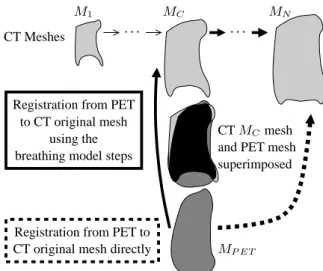
Deformation of the PET
Registration of MP ET and the original CT mesh MN
can be perform with two approaches :
(1) A direct registration (dashed line in Figure 3): MP ETRd (N ) = fRd(MP ET, MN), (2)
where fRddenotes the transformation that registers
di-rectly MP ET and MN, and MP ETRd the result of
reg-istering the PET directly to the CT mesh MN. The
transformation fRdmay be computed by any registra-tion method adapted to the problem. As an illustrative example, we choose the original CT to correspond to the end-inspiration, MN, but a similar process could be
applied for any CT image. In this approach the defor-mation itself is not guided by any anatomical knowl-edge. In addition, if the PET and the original CT are very different (end-inspiration CT), it is likely that this registration will provide physically unrealistic results. (2) To avoid such potential problems, we propose here an
alternative approach: once the appropriate CT (MC)
is selected, we compute the registration between the MP ETmesh and the MCmesh as:
MP ETr (C) = fr(M
P ET, MC), (3)
where fris the registration transformation and MP ETr denotes the registered mesh. Then, the transformation due to the breathing is used to register the MP ETr to the original CT (continuous line in Figure 3). The trans-formation due to the breathing between MC and MN
can be computed as the following composition: ΦC,N = φN−1,N ◦ . . . ◦ φC+1,C+2◦ φC,C+1. (4)
We apply to MP ETr the same transformationΦC,N in
order to compute the registration with MN: MRbm
P ET(N ) = ΦC,N(MP ETr (C))
= ΦC,N(fr(MP ET, MC)), (5)
where MP ETRbm denotes the PET registered mesh using the breathing model.
CT Meshes . . .
superimposed
Registration from PET to CT original mesh directly
and PET mesh
MP ET
. . .
Registration from PET to CT original mesh
using the breathing model steps
CT MCmesh
M1 MC MN
Figure 3. The mesh MCis the closest to the mesh MP ET.
We can register MP ET to MN following one of the two
paths (notations are defined in Section 3.3).
4
Registration Adapted to Pathologies
The algorithm described in Section 3 can be applied with any type of registration method. We show how the proposed approach can be applied for landmark-based registration of multimodality images in pathological cases, in particular for diagnosis, follow-up and radiotherapy treatments.
4.1
Influence of Selected Landmark Points
Features selection is an important task in registration. In this section, we focus on voxel selection but more com-plex features can be detected [1]. The selection can be manual (as in most methods) [24], semi-automated [16], or automated [16]. Manual selection is tedious and time-consuming. The authors in [6] suggest that semi-automated selection is interesting, integrating experts knowledge in an automatic process. Automatic selection permits reduced ex-ecution time with high accuracy. Most of these automatic
Same axial views of the lung.
MEA GAU
VL= 3431 VL= 2885
MEA-GAU MEA-GAU-UNI
VL= 3484 VL= 3794
Figure 4. Selection of landmarks – In each image, two
regions of interest are identified with two rectangles. In the large rectangle, there is no landmark withGAUmethod whereas there are four landmarks with the MEA method. In the fusion method (MEA-GAU), these landmarks are se-lected. In the small rectangle, no landmark is selected with the mean and/or the Gaussian curvatures. However, a land-mark is added in this area with theMEA-GAU-UNImethod.
methods exploit curvature [16]. In [3], an auto-correlation method is also combined with curvature.
In the present work, landmark selection is automatic and based on Gaussian and mean curvatures, according to the following steps:
(1) compute curvature for each voxel of the lung surface; (2) sort voxels in decreasing order of absolute value of
cur-vature;
(3) select voxels based on curvature and distance criteria (detailed in the following paragraph);
(4) if a uniform selection is needed then add voxels with zero-curvature in the area where no voxels have been considered as landmarks.
This algorithm is proposed to select particular voxels that provide relevant information. Moreover, we intend to obtain an approximately uniform selection to take into ac-count the entire surface of the lungs for computing the de-formation. In step 3, we considerV = {vi}i=0..NS, the
set of voxels in decreasing order of absolute value of cur-vature, where NS is the number of voxels of the surface
andVL = {vLi}i=0..NL, the set of landmarks, where NL is the number of landmarks. For each voxel vi ∈ V (for i= 0 to NS) with non-zero-curvature, we add viinVL, if ∀ vj ∈ VL, dg(vi, vj) > T where dg is the geodesic
dis-tance on the lung surface and T is a threshold to be chosen. With this selection process, some regions (the flattest) may contain no landmark, hence the addition of step 4: for each voxel on the surface of the lung vi∈ V with zero-curvature,
if there is no voxel vj ∈ VLwith dg(vi, vj) < T , we add viinVL.
Four variants are tested:
(1) MEA– Mean curvature without step 4; (2) GAU– Gaussian curvature without step 4;
(3) MEA-GAU – Using mean and Gaussian curvature without step 4;
(4) MEA-GAU-UNI– Using mean and Gaussian curvature with step 4.
When mean and Gaussian curvatures are employed (methods MEA-GAU and MEA-GAU-UNI), the set V merges the set of voxels in decreasing order of mean cur-vature and the set of voxels in decreasing order of Gaus-sian curvature, by taking alternatively a value in each set. These strategies for landmark point selection are compared in Figure 4. Results given by the MEAand GAUmethods are different, and it is interesting to combine them (see the results obtained with the MEA-GAUmethod). The MEA -GAU-UNImethod permits to add some points in locally flat regions (see Figure 4).
4.2
Rigidity Constraints in Pathological
Cases
We have developed a registration algorithm for the tho-racic region in the presence of pathologies [11]. The ad-vantage of our approach is that it takes into account the tumors, while preserving continuous smooth deformations. We assume that the tumor is rigid and thus a linear trans-formation is sufficient to cope with its movements between CT and PET images. This hypothesis is relevant and in ac-cordance with the clinicians’ point of view, since tumors are often compact masses of pathological tissue. The algo-rithm relies on previously segmented structures (lungs and tumors). Landmarks corresponding to homologous points are defined in both images, and will guide the deformation of the PET image towards the CT image. The deformation at each point is computed using an interpolation procedure based on the landmarks, the specific type of deformation of each landmark (depending on the structure it belongs to), and weighted by a distance function, which guarantees that the transformation is continuous. We have shown that a con-sistent and robust transformation is obtained [11].
4.3
Registration
with
Rigidity
Con-straints and Breathing Model
Once the different CT meshes are computed and the clos-est CT mesh, MC, is selected, the PET and the original CT
(in our example MN), are registered as follows:
(1) Select landmarks on the CT mesh MC(with Gaussian
or/and mean curvatures);
(2) Estimate corresponding landmarks on the PET (using the Iterative Closest Point algorithm [2]);
(3) i= C;
(4) Track landmarks from Mito the next CT mesh Mi+1;
(5) If Mi+1= MN, go to step (6) else go to step (4) with i= i + 1;
(6) Register (with the method summarized in Section 4.2) the PET and the original CT using the estimated corre-spondences.
In step (1), the four variants presented in Section 4.1 can be used. The breathing model is used in step (4). The land-mark points selected on MCare tracked on the meshes
es-timated with the breathing model. Consequently, we can assume that the corresponding landmarks selected on the original CT are correct (and actually they represent the same anatomical point) and follow the deformations of the lungs during the respiratory cycle.
5
Results and Discussion
In this section we present some results we have obtained using the general methodology described in Section 3 and the registration method summarized in Section 4.
We have applied our algorithm on a pathological case ex-hibiting one tumor and on a normal case. We have one PET and two CT images for each case. First, the breathing model is computed using the meshes of the lungs segmented on CT data. Then, we compare 10 (regularly distributed) instants of the generated model with the lung surface segmented from the PET (meshes have more than40 000 nodes). Fig-ure 5 shows the results of surface comparison between the PET surface, for two instants from the CT data set: the clos-est and the end-inspiration.
(a) DRM S = 12.1 (b) DRM S = 24.2
Figure 5. Superimposition of the contours of the PET
(black) and the CT lungs (grey) at two instants of the breath-ing cycle: (a) closest (MC) and (b) end-inspiration (MN).
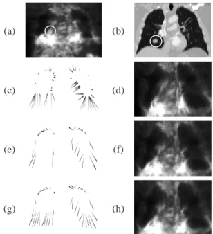
The results obtained with the proposed algorithm are physically-based and more realistic than results obtained by registering the PET directly with the original CT. First re-sults confirm this statement as shown in Figures 6 and 7. It
can be observed that the result of the registration by a direct method (Figure 6(d)) produces unrealistic deformations in the region between the lungs. With the proposed algorithm (Figure 6(h)), the result is visually more accurate. The RMS distance between the registered PET lungs and the original CT lungs is reduced to 11.8 mm. In Figure 7 the improve-ment of the results is clearly illustrated for the normal case in the region of the right lung close to the liver. All these results have been obtained by using landmarks determined by the combination of mean and Gaussian curvatures plus a uniform selection. This variant provided visually better results although further validation is necessary.
(a) (b)
(c) (d)
(e) (f)
(g) (h)
Figure 6. Original PET (a) and CT (b) images with tumor
(surrounded by a white circle). Correspondences between the selected points in the PET image and in the CT image are shown in (c), (e) and (g). Registered PET data is shown in (d) for the direct method and in (f) and (h) for the method with the breathing model with the variant combining mean and Gaussian curvatures in (e)-(f) and adding uniformly dis-tributed landmarks in (g)-(h). Illustrations are provided in 2D for the sake of readability.
(a) (b) (c)
Figure 7. Details of registration on the bottom part of right
lung, in a normal case, (a) CT, (b) PET registered with-out breathing model, (c) with breathing model. The white crosses correspond to the same coordinates.
6
Conclusion and Future Work
We have developed a CT-PET landmark-based registra-tion method that uses a breathing model to guarantee
phys-iologically plausible deformations. The method consists in computing a deformation guided by a breathing model. We also proposed and studied four variants, based on curvature, to select landmarks. Initial results on a pathological case and a normal case are very promising and show the im-provement brought by the breathing model. Our algorithm avoids undesired tumor misregistrations and preserves tu-mor geometry and intensity. Moreover, as the tutu-mor in CT and PET has not necessarily the same size and shape, the registration of these two modalities is very useful because all the information of the PET image is preserved. This is very important in order to know the true extension of the pathology for diagnosis and for the treatment of the tumor with radiotherapy, for example. Moreover, we highlight the best variant to detect landmarks: to uniformly select land-marks by combining mean and Gaussian curvatures.
We are currently performing a deeper evaluation on a larger database, in collaboration with clinicians. Future work includes a refined “snapshot” selection, using further subdivisions of time intervals, a more precise characteriza-tion of the tumor movement and its influence on the breath-ing, and a comparison of the the proposed method with other approaches which include rigid objects in the regis-tration.
Acknowledgments: This work has been partially funded
by an ANR grant: ANR-05-BLANC-0081.
References
[1] W. Beil, K. Rohr, and H. Stiehl. Investigation of approaches for the localization of anatomical landmarks in 3D medi-cal images. In Computer Assisted Radiology and Surgery
(CARS), pages 265–270, Apr. 1997.
[2] P. Besl and N. McKay. A Method for Registration of 3-D Shapes. IEEE TPAMI, 14(2):239–256, 1992.
[3] M. Betke et al. Landmark detection in the chest and tration of lung surfaces with an application to nodule regis-tration. Medical Image Analysis, 7(3):265–281, 2003. [4] O. Camara et al. Explicit Incorporation of Prior
Anatom-ical Information into a Non-Rigid Registration of Thoracic and Abdominal CT and 18-FDG Whole-Body Emision PET Images. IEEE TMI, 26(2), 2007.
[5] T. Guerrero et al. Elastic image mapping for 4-D dose estimation in thoracic radiotherapy. Radiation Protection
Dosimetry, 115(1–4):497–502, 2005.
[6] T. Hartkens et al. Using Points and Surfaces to Improve Voxel-Based Non-Rigid Registration. In MICCAI, volume 2489, pages 565–572, Tokyo, Japan, 2002.
[7] W. Lavely et al. Automatic registration of PET and CT stud-ies for clinical use in thoracic and abdominal conformal ra-diotherapy. Medical Physics, 31(5):1083–1092, 2004. [8] J. Maintz and M. Viergever. A Survey of Medical Image
Registration. Medical Image Analysis, 2(1):1–36, 1998. [9] J. McClelland et al. A Continuous 4D Motion Mmodel from
Multiple Respiratory Cycles for Use in Lung Radiotherapy.
Medical Physics, 33(9):3348–3358, 2006.
[10] J. Mead. Measurement of Inertia of the Lungs at Increased Ambient Pressure. JAP, 2(1):208–212, 1956.
[11] A. Moreno et al. Non-linear Registration Between 3D Im-ages Including Rigid Objects: Application to CT and PET Lung Images With Tumors. In DEFORM06, pages 31–40. [12] S. Nehmeh et al. Four-dimensional (4D) PET/CT imaging of
the thorax. Physics in Medecine and Biology, 31(12):3179– 3186, 2004.
[13] J. Pluim and J. Fitzpatrick. Image Registration. IEEE TMI, 22(11):1341–1343, 2003.
[14] G. Rizzo et al. Automatic registration of PET and CT studies for clinical use in thoracic and abdominal conformal radio-therapy. Physics in Medecine and Biology, 49(3):267–279, 2005.
[15] T. Rohlfing et al. Modeling Liver Motion and Deformation During the Respiratory Cycle Using Intensity-Based Free-Form Registration of Gated MR Images. Medical Physics, 31(3):427–432, 2004.
[16] K. Rohr et al. Landmark-based elastic registration using ap-proximating thin-plate splines. IEEE TMI, 20(6):526–534, 2001.
[17] A. Santhanam. Modeling, Simulation, and Visualization of 3D Lung Dynamics. PhD thesis, University of Central
Florida, 2006.
[18] A. Santhanam et al. Modeling Simulation and Visualization of Real-Time 3D Lung Dynamics. IEEE TITB, 2007. In press.
[19] D. Sarrut et al. Non-rigid registration method to assess re-producibility of breath-holding with ABC in lung cancer.
In-ternational Journal of Radiation Oncology–Biology–Physis,
61(2):594–607, 2005.
[20] W. Segars et al. Study of the Efficacy of Respiratory Gating in Myocardial SPECT Using the New 4-D NCAT Phantom.
IEEE TNS, 49(3):675–679, 2002.
[21] R. Shekhar et al. Automated 3-Dimensional Elastic Reg-istration of Whole-Body PET and CT from Separate or Combined Scanners. The Journal of Nuclear Medicine,
46(9):1488–1496, 2005.
[22] T. Sundaram and J. Gee. Towards a Model of Lung Biome-chanics: Pulmonary Kinematics Via Registration of Serial Lung Images. Medical Image Analysis, 9(6):524–537, 2005. [23] W. Vogel et al. Correction of an image size difference be-tween positron emission tomography (PET) and computed tomography (CT) improves image fusion of dedicated PET and CT. Physics in Medecine and Biology, 27(6):515–519, 2006.
[24] J. B. West et al. Hybrid point-and-intensity-based de-formable registration for abdominal ct images. In SPIE
Med-ical Imaging, volume 5747, pages 204–211, 2005.
[25] J. Wolthaus et al. Fusion of respiration-correlated pet and ct scans: correlated lung tumour motion in anatomi-cal and functional scans. Physics in Medecine and Biology, 50(7):1569–1583, 2005.
[26] B. Zitov`a and J. Flusser. Image Registration Methods: A Survey. Image and Vision Computing, 21:977–1000, 2003. [27] V. Zordan et al. Breathe Easy: Model and Control of Human
Respiration for Computer Animation. Graphical Models, 68(2):113–132, 2006.