HAL Id: hal-00795202
https://hal.archives-ouvertes.fr/hal-00795202
Submitted on 13 Feb 2014
HAL is a multi-disciplinary open access
archive for the deposit and dissemination of
sci-entific research documents, whether they are
pub-lished or not. The documents may come from
teaching and research institutions in France or
abroad, or from public or private research centers.
L’archive ouverte pluridisciplinaire HAL, est
destinée au dépôt et à la diffusion de documents
scientifiques de niveau recherche, publiés ou non,
émanant des établissements d’enseignement et de
recherche français ou étrangers, des laboratoires
publics ou privés.
Towards a multiservice & multiformat optical home area
networks
Joffray Guillory, Francis Richard, Philippe Guignard, Anna Pizzinat, Sylvain
Meyer, Benoit Charbonnier, Laurent Guillo, Catherine Algani, Hong Wu Li,
Eric Tanguy
To cite this version:
Joffray Guillory, Francis Richard, Philippe Guignard, Anna Pizzinat, Sylvain Meyer, et al.. Towards
a multiservice & multiformat optical home area networks. 14th ITG Conference on Electronic Media
Technology, Mar 2011, Dortmund, Germany. pp.2011. �hal-00795202�
Towards a Multiservice & Multiformat
Optical Home Area Network
J. Guillory, F. Richard, Ph. Guignard, A. Pizzinat,
S. Meyer, B. Charbonnier, L. Guillo.
Orange Labs, France [email protected]
C. Algani.
ESYCOM, CNAM University, France
H.W. Li, E. Tanguy.
IREENA, University of Nantes, FranceAbstract - We propose mid and long term visions of optical Home
Area Networks. The challenge is not only to increase the network capacity, but also to take into account the heterogeneity of the signals to be conveyed: Ethernet, RF TV and radio signals for wireless-end-connectivity. Two solutions are described: a mid term solution, based on an active star and centered on a multiformat switch, and a long term solution based on a fully transparent infrastructure, associated with optical wavelength multiplexing. These solutions and the corresponding realized setups will be described and compared in terms of performances, flexibility and robustness to future evolutions.
Keywords – Home Area Network; multiformat; multiservice; Ethernet; broadcast TV; Radio over Fiber; optical fiber; CWDM.
I. CONTEXT OF THE HOME AREA NETWORK
The amount of data exchanged in the Home Area Network (HAN) should drastically increase in a near future. The first reason lies in the deployment of high broadband systems in the access network, especially Fiber To The Home (FTTH) solutions which now allow the delivery of high data rate services to the end user. To avoid the last meters bottleneck, the home network has to ensure an efficient delivery of these data to the final user’s devices. The second reason is the increasing need for in-house exchanges with the interconnection of more and more devices, the home network being the convergence point of several worlds: computers, consumer electronics, television, etc... [1]. Consequently, the need for high capacity is not the only issue in the home network, another major challenge lies in the great heterogeneity of the signals to be delivered to the various home devices: IP data for triple play services, Radio Frequency (RF) signals for broadcasted TV (terrestrial or satellite), specific formats as High Definition Multimedia Interface (HDMI) signals (e.g. to link a HD disc player to a TV set). Today, all these signals have to be transmitted separately, as they cannot be encapsulated in a unique format, and specific networks working on specific media are dedicated to each application. For example, Ethernet cables for IP data carry triple play services, coaxial cables for terrestrial or satellite television broadcasting convey RF signals, specific cables for HDMI links interconnect, for instance, a High Definition (HD) player and a television set…
Another point has to be considered: the wireless connectivity is generally preferred for the final link to the device because the users find it more convenient and more
flexible. After the 300 Mbps data rate available today with Wi-Fi IEEE 802.11n, we are moving to new standards that can achieve bit-rates up to 1 Gbps in the cm-wave band (3.1-10.6 GHz) and up to 6-7 Gbps in the mm-wave band (57-66 GHz). The associated standards are ECMA 368 [2] for the cm-wave band, and ECMA 387 [3], IEEE 802.15.3c [4], Wireless HD [5], and IEEE 802.11ad [6, 7] for the mm-wave band. Among all these standards, the IEEE 802.11ad should lead the next generation of wireless solutions thanks to Wi-Fi Alliance certification and compatibly with the IEEE 802.11 family and Wireless Local Area Network systems. The drawbacks of these radio standards are their short range due to low Power Spectrum Density levels and/or the high channel attenuation in the 60 GHz band. The radio transmission is limited to a single room and to indoor open areas. So, several access points have to be installed judiciously in different rooms, and interconnected between them to ensure the coverage of the entire house.
TABLE I. RADIO STANDARDS OVERVIEW
IEEE 802.15.3c Wireless HD IEEE 802.11.ad
Released year 2009 2009 2012 Data rates 20 to 5,670 Mbps 952 to 3,807 Mbps 385 to 6,757 Mbps Main products outlook Existing products "Wireless HD" Based on IEEE 802.15.3c A/V mode. Certified products "Wi-Fi" in 2012.
The introduction of optical fibre in the HAN addresses both the bit rate increase and the great heterogeneity of the signals delivered to the various home devices, including the support of wireless end-connectivity. This results from the very high bandwidth of optical fibre, its low attenuation, high linearity, and perfect immunity to electrical interferences allowing the transmission of RF frequencies. Moreover, the Radio over Fiber (RoF) technology allows interconnecting access points or remote antennas by keeping the native radio signal format in a simple and economical way without radio/baseband transpositions, and being potentially transparent to radio layer protocols. Furthermore, the optical fibre as HAN backbone will be the natural extension of the FTTH access network. It is therefore the ideal media to provide a long life communication infrastructure inside the home, able to adapt to new standards.
Several kinds of optical fibres could be used to enable high-performance HANs: plastic optical fibres (POF), multimode
silica fibres (MMF) and singlemode silica fibres (SMF). Poly Méthyl MéthAcrylate step index plastic optical fibre (PMMA POF) is gaining momentum in HAN market as it represents a good compromise between performances and implementation easiness. Point-to-point POF links can be implemented to interconnect the home gateway and customer's devices. However, even if PMMA POF systems capacity reaches the Gbps; they will be limited to the transmission of digital signals i.e. triple play services integrated over IP and will not be able to support heterogeneous formats.
In this paper, we present our vision concerning the evolutions of an optical multiservice and multiformat HAN based on silica fibres or graded index plastic fibres. In a first step, we describe a mid-term architecture based on an active star centred on a multiformat switch. In a second step, we propose an evolution towards a longer term solution, the Broadcast and Select (B&S) architecture associated with Coarse Wavelength Division Multiplexing (CWDM), built on a fully transparent and passive infrastructure.
II. THE MULTIFORMAT ACTIVE STAR ARCHITECTURE
A. Generality
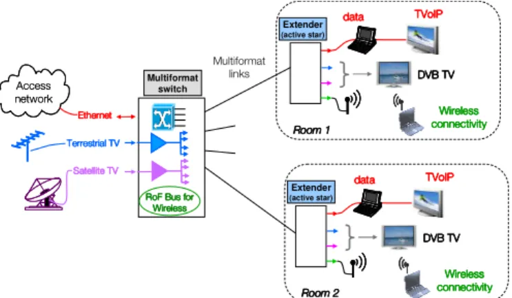
This architecture is depicted in Figure 1. The different signals, including Ethernet for IP data, terrestrial and satellite broadcast TV and radio signal, converge towards a Multiformat Switch (MS). This device integrates an Ethernet switch to manage the exchanges between the connected home devices working on the IP layer and the access network. The MS is able to process the additional analog signals. The signals coming from the TV antenna or from the satellite dish are duplicated before being sent to the different MS ports. The radio signals, coming from or going to the remote antennas, share a radio bus inside the MS, to ensure visibility between these antennas. A connection between the radio bus and the Ethernet switch is dedicated to the exchanges between wired and wireless applications. These signals are then multiplexed at each port of the MS, and conveyed on optical multiformat links towards remote plugs or extenders, located in the different rooms. Signals are then demultiplexed and delivered to connected devices, using the adapted interface. A similar process is applied for the uplink, except that we do not have uplink for the TV broadcast service.
! Extender (active star) Multiformat switch Extender (active star)
Figure 1. The multiformat star architecture.
B. A first step: an electrical multiplex
The main signals to be propagated on the multiformat links are depicted in Figure 2. They include mainly Ethernet for IP data, terrestrial and satellite broadcast TV either cm- or mm-wave radio signals. We observe that as far as IP data are carried by 100 Mbps Ethernet (Fast Ethernet), multiplexing the different signals may be achieved in the electrical domain, as there is no risk of spectrum overlapping. Taking advantage of the large bandwidth of fibers, the different multiplex related to the ports of the MS may then be carried on optical links connecting these ports to the remote extenders located in the different rooms (Figure 3).
f (MHz) 100Mbps Ethernet Terrestrial TV Satellite TV cm-wave Radio (first band) 1Gbps Ethernet →overlapping with TV broadcast
0 1000 2000 3000 4000 5000 6000 mm-wave Radio in Intermediate Frequency
(one band)
Figure 2. The electrical multiplex
LD PD
Figure 3. First step: multiplexing in the electrical domain.
This solution has been first validated by an experimental setup based on graded index plastic fibers optimized at 850 nm [8], then on OM2 silica MMF. The tested electrical multiplex was composed of 100 Mbps Ethernet, digital terrestrial television (DVB-T) and the first band of the Ultra Wide Band (UWB) radio signal (3.1 to 4.7 GHz). For low cost concern, a direct modulation and a direct photodetection have been used with 10 Gbps digital optoelectronic components: a Vertical Cavity Surface Emitting Lasers (VCSEL) as electro-optic converter and a GaAs PIN photodiodes with built-in Transimpedance Amplifier (TIA) as opto-electronic converter.
C. Towards high data rates formats.
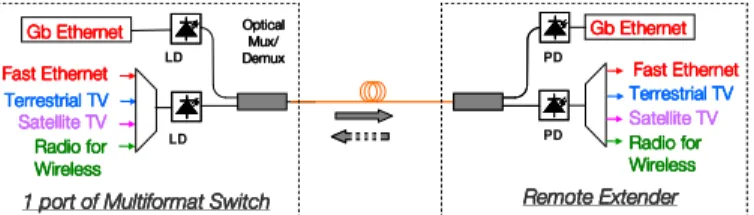
In a near future, 1 Gbps Ethernet will be needed to meet the requirements of the home applications. As shown in Figure 2, the electrical spectrum of Gigabit Ethernet and terrestrial and satellite TV overlap, and a simple electrical multiplex is no longer possible. In this case, a frequency transposition could be used, but finding the right location in the spectrum of the transposed signal could be an issue. The most efficient solution consists in introducing an hybrid optical/electrical multiplexing as depicted in Figure 4. Ethernet signal is then carried by a separate wavelength, making easier the evolution towards 1 Gbps and later 10 Gbps, while the other signals remain electrically multiplexed.
This work has been carried out in the frameworks of the projects FUI8 ORIGIN (Optical Radio Infrastructure for Gigabit/s Indoor Networks) and ICT FP7 ALPHA (Architectures for fLexible Photonic Home and Access networks).
"# "# "# "# "#"#"#"# PD PD LD LD $% $% $% $% & & & &'''' ! & ! & ! & ! &
Figure 4. Second step: hybrid multiplexing, optical and electrical.
This possibility has been demonstrated by a setup implemented on 50 m-length MMF [9]. For the optical multiplex, wavelengths have been chosen in the CWDM grid to allow the insertion of Optical Add and Drop Multiplexers (OADMs) with a minimum impact on the optical budget. The transmitters used a Fabry-Pérot laser at 1310 nm for the electrical multiplex and Small Form-factor Pluggable (SFP) module at 1290 nm for the Gigabit Ethernet in baseband format. Even if one Gigabit Ethernet link was implemented on a separate wavelength, we retained an additional Fast Ethernet channel in the electrical multiplex, as the lower part of the spectrum was free. Terrestrial digital TV and UWB radio signals completed the electrical multiplex.
Lastly, a third setup has also been tested with this time wavelengths chosen in different windows to maintain a low cost. A 850 nm VCSEL was used for the electrical multiplex, while a bidirectional monofiber SFP module was dedicated to the baseband Gigabit Ethernet, using two wavelengths, at 1.3 m and 1.5 µm, for a full-duplex transmission on a unique fiber. Thanks to the wavelength sensitivity of the photodiodes, the discrimination of the wavelengths was achieved without any additional optical filters. Optical couplers were used instead of OADMs, but only on the downlink. Consequently, the radio uplink has a favoured optical budget, which is interesting since the radio uplink is generally less efficient due to the free space losses before the optical link.
TABLE II. CONFIGURATION OF DIFFERENT SETUPS
Setup 1 Graded index PoF. Setup 2 MMF with OADMs. Setup 3 MMF with optical splitters. Electrical multiplex 850 nm 1310 nm 850 nm 1310 nm downlink Gigabit Ethernet No 1290 nm 1550 nm uplink
Until now, the MS uses the radio cm-wave band. It is simple to realize but the bit rate is limited to 1 Gbps. For Multi-Gigabit Wireless Systems (MGWS), mm-wave standards have to be chosen, but this solution is restricted by the bandwidth of the optoelectronic components, generally 10 Gbps low cost digital components. So an Intermediate Frequency over Fiber (IFoF) option is preferred. mm-waves are first down-converted to a lower frequency before modulating the laser. The signal is just mixed with a Local Oscillator (LO). At the reception side, the same procedure is applied for the up-conversion.
DC Laser TE Photodiode Optical input Optical output A antennaTX antennaRX A RF Filter Bias Tee DC Block L.O. Mixer Mixer
Figure 5. RoF transducer in Intermediate Frequency configuration.
The implementation of the mm-wave signals on the Multiformat Switch is the next step. A point-to-point Radio over Fiber link in Intermediate Frequency at 4.5 GHz (Figure 2) has already been realized and shows good results [10] at 850 nm over 50 m-length and 100 m-length OM2 MMF. Now, others services have to be added to complete the experimental setup.
D. Discussions.
The basic architecture with Fast Ethernet, digital terrestrial TV and UWB radio signal is compatible with a large choice of fiber: graded index plastic fiber, silica multimode and singlemode fibers. The graded index plastic fiber will be preferred for a quick and a simple deployment (Do It Yourself concern) whereas silica fiber would be preferred for long term evolution. Indeed, only silica fiber enables Gigabit Ethernet simultaneously with broadcast TV signals and MGWS.
Finally, the use of an optical multiplexing for each port of the MS is arguable since the price is not negligible. Moreover, considering the evolution in terms of number and diversity of signals to be supported, the active star topology may become unsuitable: first, the risk of electrical spectrum overlapping increases and secondly the number of used wavelengths on an active star must remain very limited not to multiply multiplexing and demultiplexing devices. In this case, other architectures can be preferred like the CWDM Broadcast & Select (B&S) architecture, based on a passive and optically transparent architecture.
III. LONG TERM VISION WITH CWDMB&S ARCHITECTURE
A. Generality
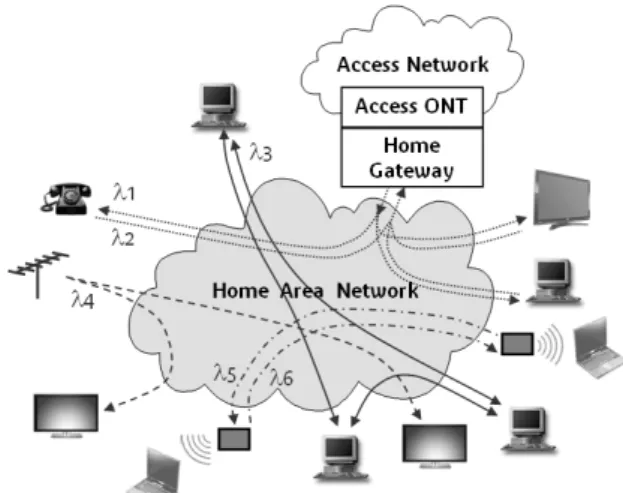
The CWDM B&S architecture is based on a passive star infrastructure centered on a NxN optical splitter. As depicted in Figure 6, in each room optical outlets are connected to this splitter through a dual-fibre cable with one fibre per transmission direction. Signal injected at any splitter input (Tx) reaches all splitter outputs (Rx). The different applications are then implemented using CWDM technology to separate incompatible formats (digital and analogue). At the reception side, an optical filter extracts only the wavelength corresponding to the wanted application. Different types of optical filters may be used, but add and drop filters are preferred, as they select one wavelength by leaving the other ones being available at the output of the module (Figure 7). It is then possible to cascade such add and drop filters on one optical outlet, providing a connection to several services at the same point.
NxN Room 1 NxN NxN Room 3 Room 2
Figure 6. The passive star infrastructure centered on a NxN optical splitter.
λ λ Σλ λ1 λ2 λ1 Σλ−λ2 λ λ Σλ λ1 λ2 λ1 Σλ−λ2
Figure 7. Optical Add & Drop filters implemented at an optical outlet.
Another important advantage of this architecture lies in its great flexibility, as it is possible to emulate simultaneously various topologies like point-to-point, point-to-multipoint and multipoint-to-multipoint, by simply choosing the adapted combinations of transmitted or selected wavelengths.
Figure 8. Example of different topologies simultaneously implemented on a CWDM B&S architecture.
B. Which IP layer on a CWDM B&S architecture?
Compared to the multiformat active star, one important difference lies in the way that data exchanges at IP level are achieved. These exchanges are based on point-to-point links in usual active star configurations, which is not fitted to a CWDM approach on an NxN passive optical plant as it results in a waste of the wavelength resource, each bidirectional point-to-point link requiring two wavelengths. It is then necessary to implement protocols designed for shared medium applications.
The simplest protocol for shared medium is the CSMA/CD protocol (Carrier Sense Multiple Access/Collision Detection). It was widely used in the LAN (Local Area Network) domain on coaxial Ethernet busses but its implementation slew down, due to the emergence of products based on switched Ethernet, in order to decrease the collision rate. As the passive star is the best solution to realize an optical bus (in terms of logical topology), the CSMA/CD protocol gains interest again. Its main advantage is it great simplicity: on a logical point of view, it is a distributed medium access control strategy, with no master in the network, while on a physical point of view, only one wavelength is shared between all the connected devices. Its main drawback is a poor QoS (Quality of Service) as this protocol was first designed for best effort exchanges, without real time requirements. However, its efficiency could benefit on one hand from the reduced number of devices and the short distances in the home network, and on the other hand from the increased Ethernet speed (1 Gbps today, 10 Gbps later).
Another more efficient protocol for shared medium has been developed for Passive Optical access Networks (PONs). Based on a multiplex in the time domain (Time Division Multiplexing downstream, Time Division Multiple Access upstream), this protocol could be applied to the CWDM B&S architecture, after being simplified to match the HAN requirements, with an adapted compromise between cost and performances. Only two wavelengths are then required, and the PON mechanisms guarantee a perfect QoS, also with coexisting real time and best effort traffic.
C. Transporting radio signals on a CWDM B&S architecture
Considering the transport of signals for wireless end-connectivity, one significant benefit of this architecture is that a LO can be easily distributed over a dedicated wavelength. So, if an IFoF transducer generates an oscillator frequency, all the other remote antennas receive the same oscillator frequency. So, this architecture is well adapted to IFoF systems.
The implementation of the mm-wave signals on the CWDM B&S is one of the next steps. A multipoint-to-multipoint Radio over Fiber link at Intermediate Frequency has already been realized over MMF at 850 nm with a 4x4 optical splitter. This kind of setup show partially good results.
Indeed, because when a radio signal is sent from a RoF transducer, all the others receive it. Consequently the shared multipoint-to-multipoint architectures induce some impairments for the radio service like multipath, echo and coupling issues [11, 12]. Then, by default, all lasers are switched-on in case of radio signals to transmit. All these lasers switched-on simultaneously induce an excess of noises and create optical beat interferences.
To avoid these issues, a solution consists in enabling the optical functions of RoF transducers (laser and photodiode) only when it is useful, and where it is necessary. This optical access management will be also beneficial to improve the Global Spectral Efficiency (in bit/s/Hz/m2). Indeed, thanks to a
full control of the optical components, power can be radiated smartly, i.e. at the right moment and at the right place. Additionally, radio waves well confined in a room reduce the health concerns by minimizing the Electro-Magnetic Fields
exposure. Lastly, the power consumption of the RoF system is optimized because of a lower number of electro-optics components turned-on simultaneously.
A solution to manage the optical architecture could consist in using information from the radio MAC layer. The optical network becomes in this way a simple extension of the radio system, fully controlled by it.
D. Experimental setup and results
The CWDM B&S architecture has been demonstrated by a first experimental setup based on SMF [13]. Several services has been run simultaneously, including a PON, a CSMA/CD LAN, a Gigabit Ethernet duplex link, a Fast Ethernet duplex link, terrestrial TV broadcasting and an UWB radio signal transmission. The observed optical spectrum for this configuration is shown on Figure 9. The center of the network was a 16x16 splitter and several add and drop filters were cascaded at some optical outlets, demonstrating the compatibility of this architecture with the optical budget of the related applications.
Figure 9. Observed optical spectrum exhibiting all the implemented wavelengths on the CWDM B&S setup.
E. One challenge: a CWDM B&S architecture on MMF
SMF was chosen to realize the CWDM B&S architecture as all the required optical elements were commercially available for this type of fiber. The relevance of implementing this architecture on SMF in the home network may be discussed: actually, WDM technology is mainly used in core and metropolitan networks, where the constraints in terms of cost are not the same as in the home network. The question of implementing this architecture on a MMF infrastructure has been raised and is presently under study. The advantage of MMF lays in the fact that low cost point-to-point systems already exist, meeting the current needs in terms of capacity. This may make easier the penetration of fiber in the home in a near future, but it has to be proven that a later migration towards a CWDM B&S architecture on MMF is possible, when the need for higher capacity or flexibility occurs.
Different setups have been realized to check the feasibility of a CWDM B&S on MMF [14, 15]. The network was centered on an 8x8 splitter, and four applications run simultaneously: CSMA/CD LAN for exchanges on IP layer, terrestrial TV broadcasting, point-to-point Gigabit Ethernet and point-to-point digital video link at 1.4 Gbps. For each application, OADM designed for MMF were used to select the dedicated wavelengths. The main difficulties raised by the lack of available optical transmitters dedicated to CWDM applications on MMF. Sources designed for SMF were then used, based on DFB (Distributed FeedBack) lasers, which exhibit a very narrow spectral width and a high coherency level. Perfectly tailored to SMF applications, these transmitters excite a very limited number of modes in the fiber, which strongly impacts the behavior of the splitter and the uniformity of the power at its outputs.
Figure 10 shows the transfer matrix of the 8x8 MMF splitter working in normal conditions, with a multimode source (a) and with a DFB laser designed for SMF (b). We may observe strong degradations of the uniformity in these latter conditions. Due to the large variations of the attenuation between the ports of the splitter, the optical budget may be seriously affected for some combinations of input and output ports of the splitter, leading to service interruption in some cases.
Figure 10. Transfer matrix of the 8x8 MMF splitter when using a multimode source (a) or a DFB laser designed for SMF.
The problem is under study, and simulations are being carried out in order to get a better understanding of the behavior of the MMF splitter according to the different source parameters. The purpose of this work is to identify the best combinations between different types of sources and splitter technology. First steps show that VCSEL should be preferred to improve the optical power uniformity at the splitter outputs, the difficulty being then to find such lasers at various wavelengths in accordance with optical filters availability. In addition, VCSEL today exist mainly at 0.8 µm, which is outside the currently standardized CWDM grid.
IV. CONCLUSION
Optical fiber has already entered the home network, with the development of low cost systems based on POF. The basic element of POF solutions consists in point to point links, using low cost media converters to optically interconnect two devices presenting standard RJ45 interfaces. As POF technology will grow, more and more devices will integrate optical ports, and it will be possible to build an optical home network without additional media converters. The network architecture will be based on multiple monoformat Ethernet point to point links, organized in active stars or daisy chains. In this first step, fiber will probably be laid as a surface installation: its capacity is too limited to be installed as a "behind the walls" backbone, such a backbone having to face further evolutions on a long time period.
For a real integration of an optical backbone in the home, silica fiber will be preferred, in association with a multiformat architecture, allowing the transport off all types of signals on a unique infrastructure. We have proposed two incremental steps for this integration: the multiformat active star and the passive star CWDM B&S architecture. These two architectures have been experimentally demonstrated with success. The first one is composed of point to point links simultaneously supporting various types of signals and connecting the ports of a multiformat switch to the different devices. We have demonstrated the possibility to transport the different signals in an electrical multiplex, with the limitation of 100 Mbps for Ethernet, or in a hybrid optical/electrical multiplex, maintaining a reasonable cost while opening the way to far higher speeds for Ethernet at 1 Gbps or 10 Gbps in the future.
The greatest flexibility and upgradability will be provided by the CWDM Broadcast & Select architecture, based on a full passive and transparent optical infrastructure. The capacity of such a network would be enormous, with the possibility to emulate at the same time several logical topologies. The connection to a service is particularly simple with this architecture as it requires only the insertion of an optical filter, without the necessity of demultiplexing all the different signals at each optical outlet. However, it appears as a long term solution for the optical elements used for its implementation are today dedicated to core or metropolitan networks, and need to be simplified to reach a compromise between costs and performances suited to the home network context.
The choice of the best fiber for the home network is also open. The active star architecture has been demonstrated on MMF, even if it works also of course on SMF. The advantage of MMF is that low cost systems exist, for a first implementation with reduced performances. As far as the need for heterogeneity or higher capacity occur, it is then possible to upgrade the system on the same infrastructure. The implementation of the CWDM Broadcast & Select architecture is easier today with SMF as all required optical modules are available, and it has been shown that some issues related to the use of MMF should be addressed. Some additional results and evolutions in the state of the art of the different optical technologies are then awaited in order to refine the best choice for the medium. Anyway, as soon as the best fibre for the home network is identified, the most efficient cabling scheme will be
based on bifiber cables converging from the different rooms towards a central point in the home. It will be then easy to achieve a seamless migration between the various architectures described in this document, by simply replacing the systems located at the extremities of the links. For example, at the convergence point of the network, the Ethernet switch of a first system generation will be replaced by a multiformat switch, and later by a NxN splitter, while multiplexers/demultiplexers located at the other extremity of the links will also be changed to be suited to the installed architecture.
REFERENCES
[1] R. Gaudino, D. Cardenas, M. Bellec, B. Charbonnier, N. Evanno, P. Guignard, S. Meyer, A. Pizzinat, I. Mollers, D. Jager, ”Perspectives in Next-Generation Home Networks: Toward Optical Solutions?”, IEEE Communication Magazine, pp. 39–47, 2010.
[2] Standard ECMA-368, ”High Rate Ultra Wideband PHY and MAC Standard”, 3rd Edition - December 2008.
[3] Standard ECMA-387, ”High Rate 60 GHz PHY, MAC and HDMI PAL”, 1st Edition - December 2008.
[4] IEEE P802.15.3c/D13, ”Part 15.3: Wireless Medium Access Control (MAC) and Physical Layer (PHY) Specifications for High Rate Wireless Personal Area Networks (WPANs). Amendment 2: Millimeter-wave based Alternative Physical Layer Extension”, July 2009.
[5] WirelessHD, “WirelessHD Specification Overview”, August 2009. www.wirelesshd.org.
[6] Standard IEEE 802.11ad, www.ieee802.org/11, May 2010. [7] WiGig, http://wirelessgigabitalliance.org.
[8] J. Guillory, Ph. Guignard, A. Pizzinat, O. Bouffant, B. Charbonnier, ”Multiservice and Multiformat Home Network based on a Low Cost Optical Infrastructure”, 35th European Conference on Optical Communication (ECOC), Septembre 2009.
[9] J. Guillory, Ph. Guignard, F. Richard, L. Guillo, A. Pizzinat, ”Multiservice Home Network based on Hybrid Electrical & Optical Multiplexing on a Low Cost Infrastructure” OSA OPC Access Networks and In-house Communications (ANIC) conference - June 2010. [10] J. Guillory, E. Tanguy, A. Pizzinat, B. Charbonnier, S. Meyer, H.W. Li,
C. Algani, "Radio over Fiber tunnel for 60 GHz wireless Home Network", Optical Fiber Communication Conference and Exposition (OFC), March 2011.
[11] J. Guillory, S. Meyer, I. Siaud, A.M. Ulmer-Moll, B. Charbonnier, A. Pizzinat, C. Algani, , 24th ed WWRF, Penang Malaysia, 2010. [12] J. Guillory, S. Meyer, I. Siaud, A.M. Ulmer-Moll, B. Charbonnier, A.
Pizzinat, C. Algani, ”RoF architectures for Multi-Gigabit Wireless Systems in the Home Area Network”, IEEE VTM, Sept 2010.
[13] Ph. Guignard et al., “Home Network based on CWDM Broadcast and Select technology,” 35th European Conference on Optical Communication (ECOC), 2007.
[14] F. Richard, Ph. Guignard, J. Guillory, L. Guillo, A. Pizzinat, A.M.J. Koonen, “CWDM Broadcast and Select Home Network based on Multimode Fibre and a Passive Star Architecture”, OSA OPC Access Networks and In-house Communications (ANIC) conference - June 2010.
[15] F. Richard, Ph. Guignard, A. Pizzinat, L. Guillo, J. Guillory, B. Charbonnier, A.M.J. Koonen, E. Ortego Martinez, E. Tanguy, H.W. Li, “Optical Home Network based on an NxN Multimode Fiber Architecture and CWDM Technology”, Optical Fiber Communication Conference and Exposition (OFC), March 2011.