DYNAMIC SIMULATION OF RESIDENTIAL BUILDINGS WITH SEASONAL
SORPTION STORAGE OF SOLAR ENERGY– PARAMETRIC ANALYSIS
Samuel Hennaut1, Sébastien Thomas1, Elisabeth Davin1 and Philippe André1 1 Building Energy Monitoring and Simulation / University of Liège (ULg), Arlon (Belgium)
1. Introduction
Efficient thermal energy storage (TES) is currently admitted as an important challenge for the future. Many reasons have led to this conclusion. These include notably the ability of TES to ensure more efficient and environmentally friendly energy use and to bridge the gap between energy supply and demand [1]. TES is particularly suited to improve solar energy use in buildings. Indeed, solar radiation is an intermittent energy source, providing significant, daily, but also yearly, power variations. In temperate or cold climate, the majority of solar radiation is received in summer while the building demand is mostly concentrated during winter. For domestic use, short term TES of solar heat, from hours to a few days, is easily feasible, typically with water tanks [2]. But, when trying to achieve a 100 % solar fraction for building heating, a seasonal TES is always necessary, even for well insulated buildings. In this case, excess solar heat produced during summer is stored to be used during winter when the solar energy is insufficient to cover building heat demand. Technologies used for seasonal TES are more complex and expensive than for short term applications [2]; that’s why it’s currently necessary to develop efficient and cheap solar TES devices [3, 4].
Thermal energy can be stored in three different ways: sensible energy, latent energy and chemical energy. The thermochemical storage (reaction enthalpy is used to store thermal energy) implies endothermic and reversible reactions, as sorption phenomenon. This kind of storage is especially well suited for long-term storage because of its high storage density and of the absence of almost all thermal losses [4]. However, this method is relatively complex.
This work focuses on the evaluation of the performances of a solar combisystem coupled to seasonal thermochemical storage using SrBr2/H20 as adsorbent/adsorbate couple. The objective is to determine the
characteristics required for solar system and storage reactor to reach a 100 % solar fraction for a building with a low heating load. The complete system, including the storage reactor, is simulated, using the dynamic simulation software TRNSYS [5]. The influence of some components and parameters of the system is estimated: weather, collectors and storage reactor parameters.
2. Long term heat storage with closed adsorption system
2.1 Adsorption reaction
This paper deals only with the adsorption reaction of water vapor on SrBr2 according to the following chemical
reaction, where is the reaction enthalpy:
(eq. 1)
Desorption is an endothermic phenomenon, so this reaction is used during summer to store solar heat while the inverse reaction is used during winter to recover the stored thermal energy. This salt is selected for its good performances at the temperature levels required for the chosen application: storage of solar heat and building low temperature heating.
2.2 Closed sorption system for long term storage
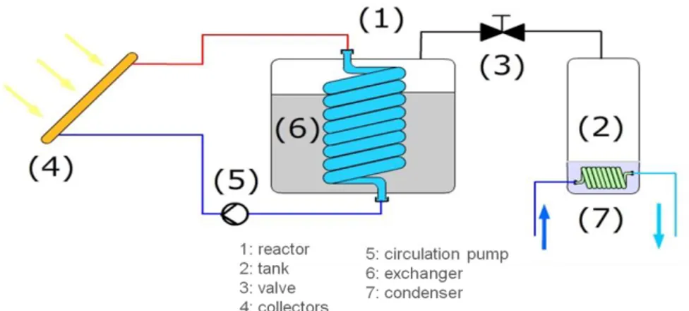
The storage device is a closed system composed of two main parts: a reactor and a water tank (see Figures 1 et 2 ). The reactor contains adsorbent salt and includes a heat exchanger. Adsorption and desorption reactions take place in this reactor. The salt is fixed in the reactor and only the water vapor moves between the reactor and the tank. An evapo-condenser takes place in the tank and is used to produce or condense water vapor. A valve is integrated between the reactor and the tank to stop vapor transfer from one part to the other one when necessary. Closed-cycle operation allows working at very low pressure to evaporate water at low temperature. 2.3 Desorption process: storage
During summer, solar radiation is converted into heat by the solar collectors. This heat is provided to the reactor. The temperature rise of the adsorbent leads to vapor desorption, corresponding to thermodynamic
equilibrium. Water desorption increases water vapor pressure in the reactor. At the same time, the evapo-condenser work as a evapo-condenser to keep a low vapor pressure in the tank. Vapor is transferred from the reactor to the tank when vapor pressure is higher in the reactor. The vapor transferred is then condensed in the tank thanks to connection to a cold source. The latent heat of condensation is released to the environment (typically with a ground heat exchanger).
Fig 1 – Closed system thermochemical storage – charging mode
2.4 Adsorption process: building heating
During winter, the condenser becomes an evaporator. Low temperature heat (typically from a ground heat exchanger) allows to vaporized water in the tank. According to the liquid-vapor and adsorption thermodynamic equilibriums, water vapor is adsorbed by the salt. The adsorption reaction releases heat used for building heating. Temperature lift of the sorbent depends directly on the evaporation temperature. Vapor is transferred from the tank to the reactor when the vapor pressure is higher in the tank.
Fig 2 – Closed system thermochemical storage – discharging mode
3. Description of the simulated system
The simulated system includes the building, the solar combisystem, the sorption storage reactor and the weather conditions. The geothermal exchanger and the evapo-condenser are not simulated with TRNSYS but the influence of its working temperature is taken into account in the reactor model.
3.1 Building energy demand
The building selected for simulations is an existing low energy building, recently built in Belgium. It’s a 100 m² living area wooden single family house, with 40 m² of the roof facing south with a 40° slope to the horizontal. The building heating demand for Uccle (Belgium) climate is around 3430 kWh/year. The monthly demand is illustrated in figure 3.
Fig 3 – Space heating demand of the reference building (Uccle climate)
3.2 Description of the combisystem
The simulated solar combisystem is shown in figure 4.
The solar radiation is converted in thermal energy using high performance flat plate collectors (HP FPC): optical efficiency (a0) = 0.80
linear loss coefficient (a1) = 1.57 W/(m²K) quadratic loss coefficient (a2) = 0.0072 W/(m²K²)
These high efficiency values are expected for the collector developed into the frame of this research project. Solar heat is stored in two water tanks: a 500 L tank for domestic hot water (DHW) and a 1000 L tank for space heating, that is fed primarily by the solar loop. An electrical auxiliary heater maintain DHW tank at 50°C. The DHW daily consumption is fixed to 200L. The building is heated with a water based heating floor fed at maximum 35°C. There is no auxiliary heater in the 1000L tank, but an auxiliary heater is added between the 1000 L tank and the heating floor to reheat water leaving the tank to 35°C if the set point temperature is not reached in the building when water in the tank is less than 35°C.
For simulations, the heating period is supposed to run from 1st of October to 30th of April. Out of this period, the tank for space heating is not used, the auxiliary heaters are switched off and the solar heat can be stored thermochemicaly. During the heating period, the upper temperature limit of the tanks is fixed to 95°C. This limit is reduced to 75°C during storage period for the DHW tank, to increase solar heat available for seasonal storage.
3.3 Integration of the long-term storage in the system
The model of thermochemical reactor used is based on the equilibrium curves adsorbent/adsorbate and liquid/vapour of the adsorbate. This model computes a dynamic energy and mass balance of the reactor, including some kinetics considerations.
The storage reactor is integrated in the solar combisystem, both in the solar loop and in the heating distribution system, as illustrated in figure 4. The heat stored thermochemicaly is only used for building heating and not for DHW production. In the solar loop, solar heat is supplied to the reactor when there is no demand for water tanks. In the distribution system, the reactor is located just after the heating tank output. The seasonal storage is used as an instantaneous auxiliary heater, if the temperature of the water leaving the tank is lower than that of the storage reactor.
As explained above, the condenser and the low temperature source/sink is not simulated. For the evapo-condenser a constant temperature is assumed. The evaporation is considered at 5°C during winter. In summer, water is condensed at 20°C. These hypotheses are nevertheless crucial because they set the working temperatures of the reactor in storage or heating mode, thus the system efficiency.
The reactor is considered as one module containing all the reactant salt and achieving only one cycle per year. If all the water is desorbed during storage period, the reactor is then used as a sensible storage until the end of this period.
Fig 4 – Schematic of the combisystem
4. Performances of the system
The performances of the system described above are evaluated using the fractional thermal energy saving indicator (Fsav,therm) developed in the framework of IEA-SHC Task 26 [6]:
(eq. 2)
Where =0.95, and is considered to be equal to the building space heating demand.
The system described above will be considered as Reference thereafter. Fsav,therm of the heating system,
excluding DHW consumption, is computed for several collector areas and adsorbent quantities (see figure 5).
Fig 5 – Fsav,therm for space heating of the reference system
greater than 15 m². The salt quantity necessary is at most 8750 kg. A detailed economical and environmental study is necessary to determine the best configuration. Currently it’s not possible to give a good estimation of this chemical storage cost. For small collector areas (10 m² and 12.5 m²), the building can’t be heated only with solar thermal energy and the curves reach a plateau for increasing salt mass. For the same simulations, if the DHW production is included in Fsav,therm evaluation (see figure 6), the fractional energy saving can’t reach 100
% anymore, because the thermochemical storage is not used as auxiliary for DHW.
Fig 6 – Fsav,therm for space heating and DHW of the reference system
In the rest of this paper, the Fsav,therm evaluations presented won’t include DHW production, even if it’s
simulated, because this work focuses mainly on autonomous solar space heating.
The efficiency of the thermochemical reactor can be defined as the ratio between heat released by the reactor and heat provided to it. The evolution of this efficiency is shown in Figure 7. For high collector area and high adsorbent mass, the efficiency is decreasing because the amount of energy chemically stored is very high compared to the needs. In these cases, the thermochemical reactor is not completely discharged at the end of the heating period.
Fig 7 – Efficiency of the thermochemical storage for the reference system
The system behavior is more detailed in Figure 8 representing the annual useful energy sources and loads, and in Figure 9 illustrating the monthly reactor energy balance for the reference system with a 17.5 m² collector and 7500 kg of SrBr2.
Fig. 8 – DHW and space heating energy source and loads for the reference system with 17.5 m² collector and 7500 kg of SrBr2
Fig 9 –Thermochemical reactor energy balance for the reference system with 17.5 m² collector and 7500 kg of SrBr2
Sensible storage occurs in the reactor in May, because its initial temperature is 20 °C and the reactor is heated at the desorption temperature. At the end of August, the reactor is completely discharged. At this time, the salt is used as a sensible storage and its temperature rises, causing an increase of thermal losses in August and September. The sensible energy stored in August is then used in October for space heating.
5. Modification of system components
5.1 Influence of the weather conditions
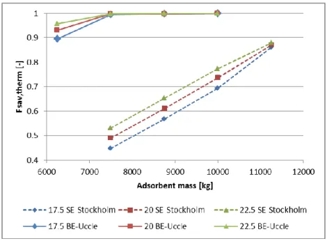
Climatic conditions influence significantly the building energy demand. The reference building and system are simulated regarding to a colder (SE - Stockholm) and a hotter (FR- Clermont-Ferrand) climate than the one of Uccle (see Figures 10 and 11). For these two locations, the building heating demand is respectively 5825 kWh/y and 2009 kWh/y.
Fig 10 – Fsav,therm for space heating of the system with Stockholm climate
For Stockholm climate, a fractional energy saving of 100 % is not reached for chosen salt masses and collector areas. It’s mainly due to the sizing of the floor heating that is unable to provide the heating powers needed for this climate. But, it seems that more than 22 m² of collector are necessary for autonomous space heating.
Fig 11 – Fsav,therm for space heating of the system with Clermont-Ferrand climate
If the building is located in Clermont-Ferrand, only 12 m² of collector are necessary to heat the building without auxiliary heater. For the same collector area, the fractional energy saving is lower than 60 % for the Uccle climate.
5.2 Influence of solar thermal collector
The influence of solar thermal collectors is also evaluated, replacing HP FPC with classical FPC (see Figure 12):
optical efficiency (a0) = 0.81;
linear loss coefficient (a1) = 3.6 W/(m²K); quadratic loss coefficient (a2) = 0.0036 W/(m²K²);
Fig 12 - Fsav,therm for space heating of the system with FPC
and evacuated tube collector (ETC) (see figure 13): optical efficiency (a0) = 0.601;
linear loss coefficient (a1) = 0.767 W/(m²K); quadratic loss coefficient (a2) = 0.004 W/(m²K²).
Fig 13 – Fsav,therm for space heating of the system with ETC
Results obtained with ETC and classical FPC are both less interesting than with the HP FPC. For FPC, 22.5 m² of collector are necessary to reach Fsav,therm = 1,with 8750 kg of salt. 15 m² of ETC can lead to a solar
autonomous heating system, as for HP FPC. But in this configuration, the system using ETC needs more salt than with HP FPC.
6. Influence of storage reactor parameters
Influence of some parameters used in the reactor model is also evaluated. This sensibility analysis is about following parameters:
Water evaporation temperature in the evaporator (Te [°C]): Te reference = 5°C ( 10°C)
(10 W/K)
Specific heat transfer coefficient through the heat exchanger (UAspec [W/(K.m²)]): UA spec reference = 500 W/(Km²) 12,5 W/(Km²)
Vapor diffusion coefficient through the salt (Deff[m²/s]): Deff reference = 10-9 m²/s (2.10-10 m²/s Vapor pressure drop between the evaporator and the salt, expressed as a valve coefficient (Cv [m³/h]):
Cv reference = 8 m³/h ( 16 m³/h)
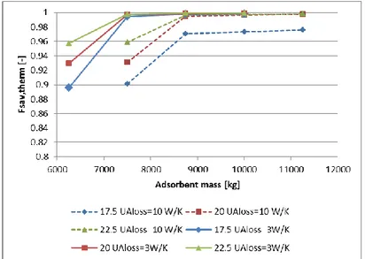
Among these parameters variations, only the thermal losses coefficient modification leads to significant variation in the Fsav,therm curves calculated (see Figure 14). For less insulated reactor, 1250 kg of salt are
necessary for the same performances. Thermochemical storage is generally presented as a storage method without loss, but it’s only partially true. In fact, sensible thermal losses can occur, during desorption and adsorption reactions, trough the reactor walls. Results presented below show the necessity to insulate the storage reactor to minimize the adsorbent quantity that is already important.
Fig 14 - Fsav,therm for space heating of the system with UAloss of the reactor of 10 W/K
7. Conclusion
In this work, collector areas and SrBr2 quantities are estimated to achieve a fractional solar energy saving for
building heating of 100 %. Influence of the climate which impacts directly the building heat demand, and of collector efficiency is studied. Consequences of the modification of some storage reactor parameters are also tested. For the reference system, considering 15 m² HP FPC and a building with a low heating demand (3430 kWh), the whole heating load can be supplied only with solar energy, using 8750 kg of SrBr2 as seasonal
thermochemical storage.
In this paper, the choice is done not to speak in terms of storage density, which is a very controversial notion for the thermochemical storage. In fact, energy density estimations should take into account the total bulk of all the components necessary to store energy and not only the salt volume. But at this stage of the project, this evaluation is very difficult.
To give a better idea, of this kind of storage application, the construction of a prototype should be the next step. But the experimental study should also be completed with an economical and environmental study to compare this application with other seasonal storage methods.
8. References
[1] I. Dincer, "Thermal energy storage systems as a key technology in energy conservation," International Journal of Energy Research, vol. 26, pp. 567-588, Jun 10 2002.
[2] P. Pinel, C. A. Cruickshank, I. Beausoleil-Morrison, and A. Wills, "A review of available methods for seasonal storage of solar thermal energy in residential applications," Renewable and Sustainable Energy Reviews, vol. 15, pp. 3341-3359, 2011.
solar and low energy buildings," presented at the Ecostock 2006 - The 10th International Conference on Thermal Energy Storage, Richard Stockton College, New Jersey, USA, 2006.
[4] K. E. N'Tsoukpoe, H. Liu, N. Le Pierrès, and L. Luo, "A review on long-term sorption solar energy storage," Renewable and Sustainable Energy Reviews, vol. 13, pp. 2385-2396, 2009.
[5] "TRNSYS simulation studio," 16.00.003 ed. Madison, Wisconsin, USA: Solar Energy Laboratory - University of Wisconsin, 2006.
[6] T. Letz, "Validation and background information on the FSC procedure," IEA SHC2002.
Acknowledgment
Research presented in this paper is conducted in the SOLAUTARK project with the following partner’s: ESE, ArcelorMittal Liège R&D, Atelier architecture Ph. Jaspard, ULB, CTIB, M5, UMons, and ULg. This project is funded by the Plan Marshall of the Walloon Region.


![[PDF] Cours administration des réseaux informatique SNMP](data:image/gif;base64,R0lGODlhAQABAIAAAP///wAAACH5BAEAAAAALAAAAAABAAEAAAICRAEAOw==)