New magnetic stimulation routes with magnetic
nanoparticles from process intensification in chemical
engineering
Thèse
Pouya Hajiani
Doctorat en génie chimique
Philosophiae Doctor (Ph.D.)
I will prepare, and some day my chance will come. Abraham Lincoln
Nothing is more common than unfulfilled potential. Howard Hendricks
Résumé
Les nanoparticules magnétiques (NPM) suscitent un vif intérêt dans plusieurs branches de l’ingénierie et de la recherche. En effet, la taille de ces dernières ainsi que leur propriétés magnétiques lorsqu’en suspension permettent leur manipulation à distance en utilisant des champs magnétiques externes appropriés. Cela ouvre la voie à l’activation de fonctionnalités supplémentaires lorsqu’ancrées à des catalyseurs métalliques, des enzymes ou des agents thérapeutiques. Conséquemment, les NPM ont été impliquées au sein de plusieurs applications dans lesquelles le mélange à l’échelle microscopique est une problématique importante, par exemple dans les réactions catalytiques, la séparation et l’administration de médicaments.
Le présent travail de thèse explore l’utilisation de NPM en tant que dispositifs nanométriques pour manipuler le mélange à l’échelle microscopique lorsque le système complet est soumis à des champs magnétiques. Toutes les expérimentations ont été menées à l’intérieur d’un électro-aimant à bobines tubulaire statique possédant deux pôles et trois phases. Ce dernier génère des champs magnétiques rotatifs uniformes (CMR), des champs magnétiques oscillatoires (CMO) ainsi que des champs magnétiques stationnaires (CMS). En premier lieu, une technique de mélange dans laquelle un CMR transforme des NPM en agitateurs nanométriques créant de petits tourbillons dans la phase liquide est présentée. L’utilisation de cette technique permet l’augmentation du coefficient de diffusion de l’eau quiescente dans une cellule de diffusion statique jusqu’à 200 fois. Les études systématiques des paramètres d’opération révèlent que l’ampleur de l’augmentation dépend de la fraction volumique en NPM ainsi que de la force et de la fréquence du champ magnétique.
En second lieu, un écoulement convectif est utilisé afin de comprendre l’effet du couple hydrodynamique sur le comportement des NPM en champs magnétiques. Des tests de distribution de temps de séjour par impulsion sont effectués avec et sans champ magnétique dans le but d’examiner la dispersion axiale d’un écoulement laminaire de Poiseuille à l’intérieur d’un tube capillaire (Tests de dispersion de Taylor). Les résultats obtenus
profil de vitesse laminaire est interprété comme provenant d’une approche d’un profil de vitesse plat similaire à celui d’un écoulement piston. À l’aide de la même technique, l’effet des CMO et des CMS sur la dispersion de Taylor et sur le profil de vitesse laminaire est aussi examiné en écoulement capillaire. Alors que les CMO n’induisent pas de mélange nano-convectif dans le capillaire et ont un impact négligeable sur la dispersion axiale, les CMS pour leur part, détériorent le mélange latéral du traceur et créent des profils de vitesse déviant de la forme parabolique vers une forme plus saillie. Une discussion détaillée de la vorticité du fluide en fonction de l’orientation du champ magnétique est aussi présentée. Finalement, un écoulement multiphasique est étudié en ciblant le transfert de matière gaz-liquide entre des bulles de Taylor d’oxygène et la phase gaz-liquide, composée d’une solution diluée de NPM, à l’intérieur de tubes capillaires soumis à des CMR, des CMO et des CMS. Les résultats indiquent que les NPM qui tournent sous l’action d’un CMR améliorent le mélange dans le film lubrificateur qui entoure les bulles de Taylor comme cela est révélé par une augmentation mesurable du kLa. À l’opposé, les CMS immobilisent les NPM, menant à des taux de transfert de matière systématiquement plus faibles alors que les CMO n’ont pas d’effet détectable sur le coefficient de transfert de matière. Par ailleurs, l’interaction entre le couple magnétique et le couple hydrodynamique nécessaire pour dominer la direction de rotation des NPM est tirée de ces résultats.
Abstract
Magnetic nanoparticles (MNPs) have attracted significant interest in diverse areas of
engineering and research. Particle size and magnetic properties of suspended MNPs in a suspension allow their manipulation at a distance using appropriate external magnetic fields. In particular by enabling additional functionality in forms anchored to metal catalysts, enzymes or therapeutic drug agents. Owing to this feature, MNPs have been involved in many applications where mixing in micro-scale is also a critical issue, e.g., catalytic reaction, separation and drug delivery.
This thesis explores MNPs as nano-scale devices to manipulate mixing in micro-scale when the whole system is subject to magnetic fields. All the experiments were performed in tubular two-pole, three-phase stator winding magnet, generating uniform rotating magnetic field (RMF), oscillating magnetic field (OMF) and stationary magnetic field (SMF).
Initially, we present a mixing technique in which a RMF converts MNPs into nano-stirrers generating small vortices in liquid phase. Using this technique, self-diffusion coefficient of motionless water in a static diffusion cell was intensified up to 200 folds. Systematic studies of operating parameters revealed that the extent of enhancement depends on MNP volume fraction, and strength and frequency in magnetic field.
In order to understand the effect of hydrodynamic torque on the MNPs behavior under magnetic fields, convective flow was also included. As such, axial dispersion of pressure-driven laminar Poiseuille flows in a capillary tube (Taylor dispersion test) was examined through a series of impulse (residence time distribution) RTD tests with and without RMF. This resulted in lateral mixing along the channel that was promoted relative to that in absence of MNPs or magnetic field. Moreover, we interpreted the observed hydrodynamic effects of such lateral mixing on laminar velocity profile as resulting from an approach to plug flow-like flat velocity profile. Using the same technique, the effect of OMF and SMF on Taylor dispersion and laminar velocity profile was examined in capillary flows. OMF did not induce nano-convective mixing in the capillary and had negligible impact on axial
velocity profiles deviating from parabolic shape towards more protruded ones. A detailed discussion of magnetic field orientation versus fluid vorticity vector was presented.
Finally a multiphase flow case concerned gas-liquid mass transfer from oxygen Taylor bubbles to the liquid in capillaries which was studied using dilute concentration of MNPs as the liquid phase under RMF, OMF and SMF. Experimental results implied that spinning MNPs under RMF improved mixing in the lubricating film that surrounds Taylor bubbles which reflected in a measurable enhancement of kLa. On the contrary, SMF pinned MNPs leading to systematically degraded gas-liquid mass transfer rates whereas axial oscillating magnetic field had no detectable effects on the mass transfer coefficient. Moreover, interaction between magnetic torque and hydrodynamic torque to dominate MNP spin direction was conceived from these results.
Acknowledgements
I would like to thank my advisor, Prof. Faical Larachi, for being a superior mentor to me who generously shared his knowledge, experience, and time with me. He has helped me become a better researcher and technical writer. I am grateful for the amount of time he spent reading and discussing the material of this thesis. His level of rigor and care in research, writing and teaching are something I will never forget and will always aspire towards in my life.
I would like to thank Dr. Hamidipour, former student of our group, for showing me the door through which I walked in and was admitted in this group. He was always being concerned about my progress.
I would like to thank Mugurel Munteanu for teaching me how to use the Vibrating Sample Magnetometer and Rodica Plesu from CERMA group who helped me to figure out how to perform particle size analysis with Zetasizer for my specific application. I also appreciate Olivier Gravel’s contribution in the lab during last four semesters. We had a lot of fun and I learned from his diverse area of interests in science and philosophy. I would like to thank Ali Faridkhou for helpful editing assistance of last two chapters of the thesis.
The help of the chemical engineering department technical staff (in Pavillon Adrien Pouliot), Jerome Noel, Marc Lavoie, and Claude Carrier during this research project is also appreciated.
I acknowledge the financial support of Natural Sciences and Engineering Research Council of Canada (NSERC) and the Canada Research Chair “Green processes for cleaner and sustainable energy”.
I would also like to thank my office colleagues for their support. To all my friends who have always been there for me as my family through all these years. The list is a long one but I would like to thank Hamidreza Radfarnia and Sanaz Mossadegh Sedghi in particular. We shared great times with each other that I will always remain in the lanes of my memory.
I would like to thank my parents, Fatemeh Shapouri and Hamidreza Hajiani, and my brother Payam. If it were not by your support over these years, I would have not made it. Thank you for giving me everything I ever wanted in life and supporting me in every endeavor I have undertaken.
My deep and sincere gratitude goes to my loving wife, Elahe, for her constant support and apprehension in this long way. During the darkest days and nights of graduate life here, I was still happy because of her even though around me there was very little reason to be so.
Foreword
This PhD thesis comprises five chapters. Each chapter represents an article published, accepted or submitted in the scientific journals. These articles are listed below.
P. Hajiani, F. Larachi, Ferrofluid applications in chemical engineering, International
Review of Chemical Engineering, 1 (2009) 221-237.
P. Hajiani, F. Larachi, Reducing Taylor dispersion in capillary laminar flows using
magnetically excited nanoparticles: Nano-mixing mechanism for micro/nanoscale applications, Chemical Engineering Journal, 203 (2012) 492-498.
P. Hajiani, F. Larachi, Giant liquid-self diffusion in stagnant liquids by magnetic
nano-mixing, Chemical Engineering and Processing, Accepted.
P. Hajiani, F. Larachi, Remotely excited magnetic nanoparticles and gas-liquid mass
transfer in Taylor flow regime, Chemical Engineering Science, Accepted.
P. Hajiani, F. Larachi, Controlling lateral mixing and velocity profile of dilute ferrofluid in
capillary in uniform DC, AC and rotating magnetic fields, Chemical Engineering Journal, Submitted.
Some results of these studies were presented in the following conferences:
P. Hajiani, F. Larachi, Lateral nano-mixing and velocity profile of dilute ferrofluid
capillary flows in uniform DC, AC and rotating magnetic fields: Single- and multiphase flow cases, IMFT, 2012, Toulouse, France.
P. Hajiani, F. Larachi, Lateral nano-mixing in micro-channel, GLS-F6, 2012, Marrakech,
Morocco.
P. Hajiani, O. Gravel, F. Larachi, Augmentation de la diffusion en milileu liquide par
rotation de nanoparticules magnétiques (npm) en champs magnétiques rotatifs, ACFAS 80, 2012, Montreal, Canada.
P. Hajiani, F. Larachi, Nano-mixing: A technique to overcome intrinsic liquid phase
self-diffusion barrier via spinning magnetic nanoparticles, NanoQuebec, 2012, Quebec, Canada.
P. Hajiani, F. Larachi, Ferrofluid applications in chemical engineering, CCEC 61, 2011,
London, Canada.
P. Hajiani, F. Larachi, Spin-up flows: Application in transport phenomena intensification,
Table of contents
Résumé ... v
Abstract ... vii
Acknowledgements ... ix
Foreword ... xi
Table of contents ... xiii
List of Figures ... xvii
List of Tables ... xxii
1 Introduction ... 1
1.1 Ferrofluids ... 1
1.2 Background ... 2
1.2.1 Response to magnetic field ... 2
1.2.2 Equilibrium magnetization ... 3
1.2.3 Relaxation time ... 3
1.2.4 Magnetization relaxation equation ... 5
1.2.5 Magnetoviscosity ... 7
1.2.6 Ferrohydrodynamic transport equations ... 13
1.3 Application ... 16
1.3.1 Pipe flow momentum transfer ... 16
1.3.2 Ferrohydrodynamic laminar model ... 18
1.3.3 Ferrohydrodynamic turbulent model ... 24
1.3.4 Porous media momentum transfer ... 31
1.3.5 Mass transfer enhancement ... 33
1.4 Scope of thesis ... 43
1.5 Nomenclature ... 44
1.6 References ... 50
2 Giant liquid-self diffusion in stagnant liquids by magnetic nano-mixing ... 55
2.1 Abstract ... 55
2.2 Introduction ... 56
2.3 Experimental ... 57
2.4 Result and discussion ... 62
2.5 Conclusion ... 65
2.6 References ... 67
3 Reducing Taylor dispersion in capillary laminar flows using magnetically excited nanoparticles: Nano-mixing mechanism for micro/nanoscale applications ... 71
3.1 Abstract ... 71 3.2 Introduction ... 71 3.3 Experimental section ... 72 3.3.1 MNP suspension ... 72 3.3.2 Magnet ... 73 3.3.3 RTD test ... 73
3.4 Results and discussion ... 74
3.4.1 Taylor dispersion test ... 74
3.4.2 MNPs alter laminar velocity profile in capillary tube ... 81
3.5 Conclusion ... 84
3.6 References ... 85
4 Controlling lateral nano-mixing and velocity profile of dilute ferrofluid capillary flows in uniform DC, AC and rotating magnetic fields ... 91
4.1 Abstract ... 91
4.2 Introduction ... 91
4.3 Experimental section ... 94
4.3.1 Magnet ... 94
4.3.2 Taylor dispersion in capillary ... 98
4.3.3 Impulse RTD test ... 98
4.3.4 Capillary tube and magnetic field relative alignment ... 100
4.3.5 Colloidal suspension ... 101
4.4 Results and discussion ... 101
4.4.1 Taylor dispersion under TRMF and TOMF ... 101
4.4.2 Taylor dispersion under SMF ... 108
4.4.3 Excited MNPs alter laminar velocity profile in capillary flow ... 114
4.5 Conclusion ... 119
4.6 Nomenclature ... 120
5 Remotely excited magnetic nanoparticles promote gas-liquid mass transfer in capillary Taylor flow regime 129 5.1 Abstract ... 129 5.2 Introduction ... 129 5.3 Experimental ... 132 5.3.1 Magnet ... 132 5.3.2 Colloidal suspension ... 134
5.3.3 Capillary tube and magnetic field relative alignment ... 134
5.3.4 Experimental setup ... 135
5.4 Results and discussion ... 137
5.4.1 Mass transfer enhancement in rotating magnetic field ... 138
5.4.2 Mass transfer enhancement in oscillating magnetic field ... 141
5.4.3 Mass transfer enhancement in static magnetic field ... 143
5.5 Conclusion ... 144
5.6 Nomenclature ... 145
5.7 References ... 147
6 Conclusion and future work ... 151
6.1 Key contributions ... 151
6.2 Suggested future work ... 152
7 Appendix A ... 155
7.1 Properties of magnetic nanoparticles (MNP) ... 155
7.2 Section II: magnet ... 157
7.3 Section III: RTD test & data reduction ... 158
List of Figures
FIGURE 1-1:STEADY-STATE ILLUSTRATION OF TYPICAL RDMNPS SUBJECT TO DC MAGNETIC FIELD IN PLANAR
COUETTE OR POISEUILLE FLOW.DEVIATION OF MAGNETIZATION FROM X DIRECTION IS DUE TO FLUID VORTICITY [2],[10] ... 8
FIGURE 1-2:ONE CYCLE OF AC-FIELD OSCILLATION ... 9 FIGURE 1-3:SCHEMATIC OF MNPS EXPOSED TO AC MAGNETIC FIELD IN PLANE COUETTE OR POISEUILLE FLOW
IN RISING ART OF THE CYCLE.DEVIATION OF MAGNETIZATION FROM X DIRECTION IS CAUSED BY FLUID VORTICITY [4] ... 10
FIGURE 1-4:SCHEMATIC OF MNPS EXPOSED TO AC MAGNETIC FIELD IN PLANE COUETTE OR POISEUILLE FLOW IN DIVING PART OF THE CYCLE.DEVIATION OF MAGNETIZATION FROM X DIRECTION IS CAUSED BY FLUID VORTICITY [4] ... 11 FIGURE 1-5:IMPACT ON AC-FIELD MAGNETOVISCOSITY PHENOMENA WITH RESPECT TO THE RELATIVE ORDER
OF BROWNIAN, HYDRODYNAMIC AND AC CHARACTERISTIC TIMES: A) ΤB> ΤH> ΤAC,∆Η>0; B) ΤB> ΤAC> ΤH, ∆Η>0; C) ΤAC> ΤB> ΤH,∆Η<0 ... 12 FIGURE 1-6:OSCILLATING MAGNETIC FIELD CAUSES SYNCHRONIZED ROTATION OF RDMNPS WHEN ΤAC> ΤB>
ΤH ... 12 FIGURE 1-7:COUETTE FLOWS OF FERROFLUID CONFINED BETWEEN TWO PARALLEL PLATES SUBJECT TO
MAGNETIC FIELD.ADAPTED FROM [22] ... 15 FIGURE 1-8:FRACTIONAL PRESSURE DROP VERSUS FERROFLUID REYNOLDS NUMBER MEASURED AT DIFFERENT STRENGTHS OF 400HZ AC MAGNETIC FIELD.ADAPTED FROM [25] ... 17
FIGURE 1-9:SIMULATED PROFILES OF NORMALIZED VELOCITY U, SPIN VELOCITY Ω AND AVERAGED MAGNETIC BODY TORQUE T0 FOR FERROFLUID LAMINAR PIPE FLOW EXPOSED TO OSCILLATING MAGNETIC FIELD (948
OE,60HZ) IN COMPARISON WITH ZERO FIELD PROFILES.ADAPTED FROM [25]. ... 21
FIGURE 1-10:FITTED BROWNIAN TIME CONSTANT VERSUS FERROFLUID REYNOLDS NUMBER AT DIFFERENT
AC-FIELD FREQUENCIES.ADAPTED FROM [25]) ... 21 FIGURE 1-11:SIMULATED PROFILES OF NORMALIZED VELOCITY U, SPIN VELOCITY Ω AND AVERAGED
MAGNETIC BODY TORQUE T0, TURBULENT KINETIC ENERGY K AND TURBULENT DISSIPATION RATE Ε FOR FERROFLUID TURBULENT PIPE FLOWS EXPOSED TO OSCILLATING MAGNETIC FIELD (948OE,60HZ).
ADAPTED FROM [25]. ... 22
FIGURE 1-12:COMPARISON OF SIMULATED RE-DEPENDENT FRACTIONAL PRESSURE DROP WITH EXPERIMENTAL DATA FOR DIFFERENT OSCILLATING MAGNETIC FIELD STRENGTH.MAGNETIC FIELD FREQUENCY (A)60HZ, (B)400HZ,(C)1000HZ.ADAPTED FROM [25]. ... 24
FIGURE 1-13:EFFECT OF MAGNETIC FIELD STRENGTH (EMBEDDED IN DIMENSIONLESS MAGNETIC FIELD, ON
(A)RMS SPIN VELOCITY,(B)RMS LINEAR VELOCITY,(C) ON AVERAGED ENERGY TERMS:◊ FOR ΦB;○ FOR
ΕV;□ FOR ΨS;+ FOR ΕC; FOR ΕA, IN TURBULENT MODEL.ADAPTED FROM [15] ... 29
FIGURE 1-14:POROUS MEDIUM AND FLOW DETAILS:PACKED BED AND MAGNETIC FIELD PROGRAMMING [30] 32
FIGURE 1-15:SPIN VELOCITY PROFILES AND POSITIVE/NEGATIVE GRADIENT MAGNETIC FIELD AT (A) BED EXIT Z
=L,RE =2110.BOX LEGEND SYNTAX:A(+) H0Z =A Z/LOE;A(-) H0Z =A(1- Z/L)OE,[30] .... 32 FIGURE 1-16:AXIAL VELOCITY COMPONENT RADIAL PROFILES AND POSITIVE/NEGATIVE GRADIENT MAGNETIC
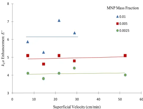
FIELD AT BED EXIT Z =L AND FERROFLUID REYNOLDS NUMBERS RE =21.1.BOX LEGEND SYNTAX:A(+) H0Z=A Z/LOE;A(-) H0Z=A(1- Z/L)OE,[30] ... 33 FIGURE 1-17:ENHANCEMENT FACTOR VS.MNP MASS FRACTION AT 300 AND 500 STIRRER SPEED, PHYSICAL
ABSORPTION TESTS.ADAPTED FROM [34] ... 36
FIGURE 1-18:ENHANCEMENT VS. DISSIPATED ENERGY AT THREE DIFFERENT MNP CONCENTRATIONS IN CHEMICAL ABSORPTION TESTS AT VS =14.5 CM/MIN.ADAPTED FROM [34] ... 36
FIGURE 1-20:KLA, A,KL ENHANCEMENT VS. DISSIPATED ENERGY AT THREE DIFFERENT MNP
CONCENTRATIONS IN CHEMICAL ABSORPTION TESTS AT VS =14.5 CM/MIN.ADAPTED FROM [34] ... 37
FIGURE 1-21:KLA, A,KL ENHANCEMENT VS. SPECIAL VELOCITY AT THREE DIFFERENT MNP CONCENTRATIONS IN CHEMICAL ABSORPTION TESTS AT POWER P.U.V =2.1 KW/M3.ADAPTED FROM [34] ... 38 FIGURE 1-22:STABILITY OF MAGNETIC NANOPARTICLE SIZES AT DIFFERENT CONCENTRATIONS OF MDEA VS.
TIME.ADAPTED FROM [36] ... 39
FIGURE 1-23:PARTICLE SIZE DISTRIBUTION OF SILICA AGGREGATES (VOLUME FRACTION SCALE), FLUID AT REST (BLACK LINE), AFTER 1 H,RE =26000 IN ABSENCE (RED LINE), AND IN PRESENCE (BLUE LINE) OF EXTERNAL MAGNETIC FIELD.ADAPTED FROM [37] ... 41
FIGURE 1-24:PARTICLE SIZE EVOLUTION OF SILICA AGGREGATES IN PRESENCE (BLUE LINE) AND ABSENCE
(RED LINE) OF EXTERNAL MAGNETIC FIELD,RE =8000.ADAPTED FROM [37] ... 42 FIGURE 1-25:MEAN DIAMETER OF Γ-ALUMINA CLUSTERS FORMED IN PRESENCE OF MAGNETIC FIELD (BLUE
LINE) AND IN ABSENCE OF MAGNETIC FIELD (RED LINE) VERSUS REYNOLDS NUMBER.ADAPTED FROM [37]
... 42 FIGURE 2-1: A)TOP AND SIDE VIEW OF THE MAGNET WITH DIFFUSION CELL EMBEDDED INSIDE WITH CELL
CONTAINING MNP SUSPENSION. B)DIFFUSION CELL SUBJECT TO URMF GENERATED BY TWO-POLE THREE
-PHASE MAGNET ENERGIZED BY A THREE-PHASE POWER SUPPLY. C)DIFFUSION CELL WITH TWO SETS OF ELECTRICAL CONDUCTIVITY SENSORS. ... 59
FIGURE 2-2:ELECTRODE RESPONSES OF A CONDUCTIVITY CELL, WITH AND WITHOUT URMF NANO-MIXING STIMULATION.MINUTE VOLUME OF TRACER IS INJECTED UPSTREAM INTO THE CAPILLARY TUBE (D =1 MM) AND TRACKED AT TWO POSITIONS, FIVE AND THIRTY-FIVE MM DOWN THE INJECTION POINT BY TWO SETS OF ELECTRODES MEASURING CROSS-SECTIONAL AVERAGE ELECTRICAL CONDUCTIVITY.TRENDS REPRESENT THE TIME EVOLUTION OF TRACER CONDUCTIVITY AS DETECTED BY UPSTREAM AND DOWNSTREAM ELECTRODES A) MAGNETIC FIELD DISABLED,=0.004 AND B) MAGNETIC FIELD ENABLED UNDER URMF,=0.01,H0=31.4 KA/M, F =100HZ ... 61
FIGURE 2-3:SCHEMATIC DIAGRAM OF MNPS SPIN IN HYDROSTATIC CONDITIONS WITH AND WITHOUT URMF (A)IN ABSENCE OF MAGNETIC FIELD,MNPS GYRATION AND TRANSLATION IS SOLELY DUE TO BROWNIAN THERMAL AGITATION;MNP TIME-AVERAGE SPIN VECTOR () IS EQUAL TO ZERO SINCE MNP MAGNETIC MOMENTS (M) ARE RANDOMIZED IN ALL DIRECTIONS;(B)IN PRESENCE OF URMF(H0),MNP SPIN VECTOR
() TURNS NORMAL TO H0 AND HENCE LATERAL MIXING OCCURS IN ALL DIRECTIONS ALONG CAPILLARY.
... 63 FIGURE 2-4:DIFFUSION ENHANCEMENT FACTOR UNDER URMF VERSUS A) MAGNETIC FIELD STRENGTH, B)
MAGNETIC FIELD FREQUENCY AND C)MNP CONCENTRATION.D0 IS LIQUID SELF-DIFFUSION COEFFICIENT WITHOUT MAGNETIC FIELD ... 65
FIGURE 3-1:TAYLOR DISPERSION IN CAPILLARY TUBE EXPOSED TO A ROTATING MAGNETIC FIELD (A)
DISPERSION OF A TRACER PLUG IN POISEUILLE FLOW;(B)EXPERIMENTAL SETUP CONSISTS OF A TWO-POLE THREE-PHASE TUBULAR MAGNET (6 CM LONG,4.5 CM I.D.) POWERED BY A THREE-PHASE POWERSUPPLY TO GENERATE A TRANSVERSE ROTATING MAGNETIC FIELD (WITH VARIABLE FREQUENCY AND STRENGTH) ACROSS A COAXIALLY ALIGNED GLASS CAPILLARY (10 CM LONG,1 MM I.D.)(C)MAGNET UPPER VIEW SHOWING A UNIFORM HORIZONTAL ROTATING MAGNETIC FIELD OVER A CAPILLARY FLOW OF A DILUTE SUSPENSION OF MAGNETIC NANOPARTICLES ... 75
FIGURE 3-2:SCHEMATIC DIAGRAM OF MNPS SPIN IN SHEAR FLOW WITH AND WITHOUT TRMF(A)IN THE ABSENCE OF MAGNETIC FIELD,MNPS GYRATE SYNCHRONOUSLY WITH FLUID VORTICITY;MNP SPIN VECTOR () IS EQUAL HALF FLUID VORTICITY (1/2×V) AND MNP MAGNETIC MOMENTS (M) ARE
RANDOMIZED IN ALL DIRECTIONS;(B)IN PRESENCE OF TRMF(H0),MNP SPIN VECTOR () TURNS NORMAL TO AZIMUTHAL FLUID VORTICITY VECTOR AND HENCE MIXING IS LATERAL.MIXED SPHEROID ZONES FORM AROUND MNPS WHEN MAGNETIC TORQUE (0M×H, M IS MNP MAGNETIC MOMENT,H IS MAGNETIC FIELD AND 0 IS VACUUM PERMEABILITY) OVERCOMES BROWNIAN AGITATION AND FRICTIONAL TORQUE
(2(×U-2), U IS LINEAR FLUID VELOCITY, IS LOCAL MNP SPIN, IS SPIN VISCOSITY).THE DISTANCE BETWEEN STIRRED SPHEROIDS IS AFFECTED BY MNP CONCENTRATION AND TRMF FREQUENCY.
SIGNIFICANT MIXING OCCURS WHEN MOST OF THE STIRRED ZONES OVERLAP TO ASSIST MATERIAL
EXCHANGE AMONGST THEM. ... 76
FIGURE 3-3:IMPULSE RESPONSE OF A TAYLOR DISPERSION CAPILLARY WITH AND WITHOUT NANO-MIXING (A) SCHEMATIC OF TAYLOR DISPERSION CAPILLARY TUBE WITH TWO SETS OF DETECTORS INSIDE MAGNET BORE; (B,C)LAMINAR POISEUILLE FLOW IN A CAPILLARY TUBE: D =1 MM,PE ~103,RE ~1.A PLUG OF TRACER IS INJECTED UPSTREAM INTO THE CAPILLARY TUBE AND TRACKED AT TWO POSITIONS, FIVE AND EIGHT CM DOWN THE INJECTION POINT BY TWO SETS OF ELECTRODES MEASURING CROSS-SECTIONAL AVERAGE ELECTRICAL CONDUCTIVITY.TRENDS REPRESENT THE TIME EVOLUTION OF TRACER CONDUCTIVITY AS DETECTED BY UPSTREAM AND DOWNSTREAM ELECTRODES (■,□) FOR UNSTIRRED POISEUILLE FLOW,(▲,Δ)
NANO-MIXING FOR LATERALLY STIRRED MNPS =0.0025,H0=10.4 KA/M, F =50HZ,(●,○) NANO -MIXING FOR LATERALLY STIRRED MNPS =0.0025,H0=36.5 KA/M, F =50HZ.PEAK NARROWING INDICATES AXIAL DISPERSION IS REDUCED UNDER NANO-MIXING. ... 77
FIGURE 3-4:THE EFFECT OF CONVECTIVE FLOW ON AXIAL DISPERSION ATTENUATION AXIAL DISPERSION COEFFICIENT, PRESENTED AS DIMENSIONLESS NUMBER D/UL, AND ESTIMATED FROM MOMENT ANALYSIS OF CONVOLUTED DATA FROM IMPULSE TESTS (SUCH AS IN FIGURE 3-3).EXPERIMENTS PERFORMED WITH = 0.001,H0=31.4 KA/M.MILDER SLOPES IMPLY STRONG NANO-MIXING COUNTERACTING CONVECTIVE STRETCHING.ERROR BARS INDICATE STANDARD DEVIATION (NUMBER OF REPEAT RUNS =3) ... 78
FIGURE 3-5:AXIAL DISPERSION ATTENUATION IS DEPENDENT ON TRMF STRENGTH AND FREQUENCY, AND MNP CONCENTRATION AND CORE DIAMETER.EXPERIMENTS CARRIED OUT AT =0.001 AND MNP MEDIAN DIAMETER DC=16.0 NM UNLESS OTHERWISE STATED.(A)D/D0 VERSUS F (▲) AT H0=31.4 KA/M PLATEAUS AT ABOUT 50HZ.D/D0 VERSUS H0(●) AT F =50HZ.(B)D/D0 VERSUS () AT H0=31.4 KA/M PLATEAUS AT ABOUT 0.0012.D/D0 VERSUS DC(■)AT H0=36.5 KA/M AND F =50HZ.ERROR BARS INDICATE STANDARD DEVIATION (NUMBER OF REPEAT RUNS =12). ... 80
FIGURE 3-6:MIXING EFFECT ON LAMINAR VELOCITY PROFILE.POWER-LAW INDEX N AND /MIN RATIO AS A
FUNCTION OF (A) MAGNETIC FIELD STRENGTH,(B) MAGNETIC FIELD FREQUENCY,(C)MNP VOLUME FRACTION.
ERROR BARS INDICATE STANDARD DEVIATION (NUMBER OF REPEAT RUNS =6),(D)SIMULATED LAMINAR FLOW VELOCITY PROFILE FOR DIFFERENT LATERAL MIXING INTENSITIES IN A CAPILLARY AS A FUNCTION OF POWER-LAW INDEX. ... 83 FIGURE 4-1:TAYLOR DISPERSION IN CAPILLARY TUBE EXPOSED TO MAGNETIC FIELD. A)SCHEMATIC DRAWING
DEPICTS DISPERSION OF A TRACER BLOB IN POISEUILLE FLOW WITH PARABOLIC LAMINAR VELOCITY PROFILE. B)SCHEMATIC OF THE EXPERIMENTAL SETUP INCLUDING TWO-POLE THREE-PHASE MAGNET AND GLASS-MADE CAPILLARY TUBE AT THE CENTER. C)UPFRONT VIEW OF MAGNET WITH A CAPILLARY SET VERTICALLY AND COAXIALLY WITH MAGNET BORE, A UNIFORM HORIZONTAL MAGNETIC FIELD IMPOSED ACROSS CAPILLARY TUBE HOSTING A FLOW OF MNP-LADEN SUSPENSION. ... 96 FIGURE 4-2:TAYLOR DISPERSION CAPILLARY TUBE SUBMITTED TO THREE MAGNETIC FIELD SCENARIOS.TWO
-POLE THREE-PHASE MAGNET GENERATES A) UNIFORM ROTATING MAGNETIC FIELD (RMF) WHEN ENERGIZED BY A THREE-PHASE POWER SUPPLY, B) OSCILLATING MAGNETIC FIELD (OMF) WHEN ENERGIZED BY A SINGLE-PHASE POWER SUPPLY, C) UNIFORM STATIC MAGNETIC FIELD (SMF) WHEN ENERGIZED BY A DC CURRENT.PERPENDICULAR TO (Y,X) PLANE IS Z-DIRECTION. ... 97 FIGURE 4-3:IMPULSE TEST OF A TAYLOR DISPERSION CAPILLARY WITH AND WITHOUT RMF. A)SCHEMATIC
DRAWING OF TAYLOR DISPERSION CAPILLARY TUBE WITH TWO SETS OF DETECTORS FIVE AND EIGHT CM DOWN THE INJECTION POINT. B)RTD RESPONSES FROM FIRST (FULL MARKS) AND SECOND (EMPTY MARKS) ELECTRODE.TRENDS REPRESENT TIME EVOLUTION OF TRACER IMPULSE RESPONSES, RESPECTIVELY, OF FIRST AND SECOND ELECTRODES (INTENSITY IN ARBITRARY UNITS):(■,□) FOR MAGNETIC-FIELD-FREE
H0=36.5 KA/M, F =50HZ).PEAK NARROWING INDICATES LATERAL MIXING UNDER ROTATING MAGNETIC FIELD. C, D)SCHEMATIC DIAGRAM OF MNPS SPIN IN SHEAR FLOW WITH AND WITHOUT RMF. C)IN THE ABSENCE OF MAGNETIC FIELD,MNP SPINS,, GYRATE COLLINEAR TO FLUID VORTICITY AND MNP
MAGNETIC MOMENTS (M) ARE RANDOMIZED IN ALL DIRECTIONS. D)UNDER TRANSVERSE RMF(H0), BECOMES PERPENDICULAR TO AZIMUTHAL FLUID VORTICITY AND HENCE, MIXING IS LATERAL.IT IS EXPECTED THAT A MIXED ZONE FORMS AROUND MNP WHEN MAGNETIC TORQUE, M×H OVERCOMES
BROWNIAN THERMAL AGITATION AND VISCOUS SHEAR FORCES. ... 100 FIGURE 4-4: AXIAL DISPERSION COEFFICIENT IN CAPILLARY WITH LOW RE NUMBER SUBJECTED TO TRANSVERSE
OMF AND RMF. AXIAL DISPERSION COEFFICIENT, COMPACTED IN DIMENSIONLESS NUMBER UL/D, ESTIMATED FROM IMPULSE RTD TESTS.EXPERIMENTS PERFORMED AT =0.001, D/=1.0,H0=31.4 KA/M FOR TRMF AND H0RMS=31.4 KA/M FOR TOMF.AXIAL DISPERSION ATTENUATION UNDER TRMF IMPLIES THAT IT
CHANGES ORIENTATION OF MNP SPIN VECTORS THUS INDUCING LATERAL MIXING IN CAPILLARY WHILST UNDER TOMF,MNP BEHAVIOR DOES NOT SHOW SIGNIFICANT CHANGE RELATIVE TO NO MAGNETIC FIELD TESTS.ERROR BARS INDICATE STANDARD DEVIATION (TRIPLICATE TESTS). ... 104
FIGURE 4-5:RELATIVE AXIAL DISPERSION COEFFICIENT IN CAPILLARY UNDER TOMF AND TRMF.K0=3.47×10⁻⁶ M2/S IS AXIAL DISPERSION COEFFICIENT OF DILUTE FERROFLUID (=0.001) WITHOUT MAGNETIC FIELD EXCITATION.MODERATE-STRENGTH TOMF AT LOW FREQUENCY CANNOT EXCITE MNPS TO REFLECT IN NOTABLE EFFECTS ON AXIAL DISPERSION.AXIAL DISPERSION ATTENUATION UNDER TRMF OCCURS AND REACHES A PLATEAU AFTER A CERTAIN FREQUENCY.ERROR BARS INDICATE STANDARD DEVIATION (N =12).
... 104 FIGURE 4-6:MNP RESPONSE TO TOMF IN A POSITION WHERE MAGNETIC FIELD DIRECTION IS PERPENDICULAR TO
FLUID VORTICITY, A)MAGNETIC FIELD IS STRONG ENOUGH TO ORIENT MNPS TO ITS DOMINANT DIRECTION, B) TOMF PASSES BRIEFLY THROUGH ZERO WHILE CHANGING DIRECTION LEAVING MNP MAGNETIC MOMENTS SHORTLY UNASSISTED TO LOSE, DUE TO RANDOMIZATION EFFECT OF BROWNIAN COLLISIONS, THEIR COHERENT DIRECTION, C)MAGNETIC FIELD ON THE RISE UNTIL PEAK AND MNP MAGNETIC MOMENTS TO RESUME
ORIENTATIONAL COHERENCE.SYNCHRONOUS PARTICLE ROTATION DRIVEN BY TOMF IS PROHIBITED BY MIDWAY BROWNIAN RESHUFFLING OF MNPS. ... 106
FIGURE 4-7:MNP RESPONSE TO OMF IN A POSITION WHERE MAGNETIC FIELD DIRECTION IS PARALLEL TO FLUID VORTICITY.MNP GYRATION UNDER SHEAR FLOW IS NOT OPPOSED BY MAGNETIC TORQUE.AS A RESULT, THERE IS NO MOMENTUM TRANSFER BETWEEN MNP AND FLUID DUE TO OMF-NANOPARTICLE INTERACTIONS. ... 108 FIGURE 4-8:IMPULSE TEST OF A TAYLOR DISPERSION CAPILLARY WITH AND WITHOUT SMF. A)SCHEMATIC
DRAWING OF TAYLOR DISPERSION CAPILLARY TUBE WITH TWO SETS OF DETECTORS ONE AND FOUR CM DOWN THE INJECTION POINT, B)RTD RESPONSES FROM FIRST (FULL MARKS) AND SECOND ELECTRODE (EMPTY MARKS).TRENDS REPRESENT THE TIME EVOLUTION OF TRACER INTENSITY FROM FIRST AND SECOND ELECTRODES, RESPECTIVELY,(▲,Δ) WITH UNEXCITED MNPS FLOWING IN LAMINAR POISEUILLE FLOW,(●,○) WITH EXCITED MNPS (=0.0025,H0=31.4 KA/M).AXIAL DISPERSION INCREASES IN CAPILLARY WHEN MAGNETIC TORQUE PREVENTS MNPS GYRATION UNDER SHEAR FLOW. ... 110 FIGURE 4-9:SCHEMATIC OF MNPS MOTION UNDER SHEAR FLOW IN CAPILLARY TUBE. A)MAGNETIC FIELD FREE,
PARTICLES GYRATE BY FRICTION TORQUE AND THEIR MAGNETIC MOMENTS DIRECTIONS ARE RANDOMIZED. B) UNDER ASMF, HARD DIPOLES ARE LOCKED BY THE COAXIALLY APPLIED EXTERNAL MAGNETIC FIELD.
NANOMETRICALLY, THE VELOCITY GRADIENT HAS BEEN REMOVED IN SOME REGIONS (WHERE HIGHLIGHTED) AND AUGMENTED IN THE REST TO SATISFY CONTINUITY (BLACK DOTTED LINE).THAT MAY RESULT IN MIMETIC SHEAR THICKENING BEHAVIOUR OF LIQUID UNDER ASMF.THE BROWN DASH-DOTTED LINE REPRESENTS THE ORIGINAL PARABOLIC VELOCITY PROFILE AS IT OCCURS IN A). ... 111 FIGURE 4-10:AXIAL DISPERSION PERTURBATIONS UNDER TRMF AND ASMF VERSUS A) MAGNETIC FIELD STRENGTH AND B)MNP CONCENTRATION. A, B)ASMF PROMOTES AXIAL DISPERSION (●,) WHILST TRMF ATTENUATES
K/K0(,▲).ERROR BARS INDICATE STANDARD DEVIATION (NUMBER OF REPEAT RUNS =6).
WHEREAS MAGNETICALLY SPINNING MNPS UNDER TRMF PROMOTE LATERAL MASS TRANSFER THROUGH NANOCONVECTIVE MIXING.IN A)K0(=0.001,TRMF)=3.47×10⁻⁶ M2/S AND K0(=0.005,ASMF)=1.13×10⁻⁶ M2/S.IN B)K0(=0,TRMF)=5.08×10⁻⁶ M2/S AND K0(=0,ASMF)=1.11×10⁻⁶ M2/S. ... 113
FIGURE 4-11:EXCITED MNPS EFFECT ON LAMINAR VELOCITY PROFILE UNDER TRMF AND ASMF.POWER-LAW INDEX N AND /TMIN RATIO AS A FUNCTION OF A) MAGNETIC FIELD STRENGTH, B)MNP VOLUME FRACTION. ERROR BARS INDICATE STANDARD DEVIATION (NUMBER OF REPEAT RUNS =6). C)EXPECTED LAMINAR FLOW VELOCITY PROFILE IN A CAPILLARY AS A FUNCTION OF POWER-LAW INDEX. ... 116
FIGURE 4-12:EFFECTIVE DIFFUSIVITY IN LAMINAR FLOW UNDER TRMF AND ASMF.DEFF/D RATIO AS A FUNCTION
OF A) MAGNETIC FIELD STRENGTH, B)MNP VOLUME FRACTION. ... 119 FIGURE 5-1:TAYLOR BUBBLES IN CAPILLARY TUBE EXPOSED TO MAGNETIC FIELD: A) EXPERIMENTAL SET-UP
INCLUDING TWO-POLE THREE-PHASE MAGNET AND GLASS-MADE CAPILLARY TUBE AT THE CENTER; B) UPFRONT VIEW OF MAGNET WITH CAPILLARY SET VERTICALLY AND COAXIALLY WITH MAGNET BORE, AND UNIFORM HORIZONTAL MAGNETIC FIELD IMPOSED ACROSS CAPILLARY TUBE HOSTING A FLOW OF MNP-LADEN SUSPENSION; C) RISING TAYLOR BUBBLES IN CAPILLARY; D) EXPANDED AREA OF LUBRICATING FILM WHERE MNP SPIN PLANE IS PERPENDICULAR TO CAPILLARY WALL. ... 133 FIGURE 5-2: A)EXPERIMENTAL SET-UP FOR GAS-LIQUID MASS TRANSFER STUDY IN CAPILLARY; B) SINGLE
TAYLOR BUBBLE SURROUNDED BY SPINNING MNPS IN A TRMF ... 137 FIGURE 5-3: A)CAPILLARY TUBE LOCATED COAXIALLY IN THE BORE OF A TWO-POLE THREE-PHASE MAGNET
(TOP VIEW).MAGNET GENERATES A UNIFORM ROTATING MAGNETIC FIELD (RMF) WHEN ENERGIZED BY A THREE-PHASE POWER SUPPLY; B) KLA ENHANCEMENT FACTOR AS A FUNCTION OF TRMF FREQUENCY:FOR EXPERIMENTS UNDER MAGNETIC FIELD (,▲,●), ENHANCEMENT WAS DUE TO TRMF AND KLA0 IS MASS TRANSFER COEFFICIENT IN ABSENCE OF MAGNETIC FIELD FOR EACH PARTICLE CONCENTRATION,UL=0.1 CM/S,
UG=0.3 CM/S AND H0=31.4 KA/M.FOR KLA VERSUS GAS FLOW RATE WITHOUT MAGNETIC FIELD (■), ENHANCEMENT ORIGINATED FROM GAS FLOW AUGMENTATION AND KLA0 CORRESPONDS TO UG=0.3 CM/S. OTHER PARAMETERS ARE THE SAME (I.E.,=0 AND UL=0.1 CM/S); C) KLA ENHANCEMENT FACTOR UNDER TRMF AS A FUNCTION OF U
G FOR TWO MNP CONCENTRATIONS WHILE UL,H0 AND WERE KEPT CONSTANT.
... 140 FIGURE 5-4: A)SIDE VIEW OF THE MAGNET WITH A CAPILLARY TUBE WHICH WAS SET VERTICALLY AND
TRANSVERSE WITH MAGNET BORE, A UNIFORM VERTICAL MAGNETIC FIELD IMPOSED ALONG CAPILLARY TUBE; B) RISING TAYLOR BUBBLES SURROUNDED WITH AZIMUTHALLY SPINNING MNPS ARE SHOWN.
FLUID VORTICITY AND CONSEQUENTLY, PARTICLE SPIN VECTOR INVERTED OVER FILM THICKNESS; C) THE MAGNET GENERATES A UNIFORM OSCILLATING MAGNETIC FIELD (OMF) WHEN ENERGIZED BY AN AC
POWER SUPPLY; D) KLA ENHANCEMENT FACTOR VERSUS FIELD FREQUENCY FOR THREE PARTICLE
CONCENTRATIONS EXPOSED TO H0 RMS=31.4 KA/M. KLA0 IS MASS TRANSFER COEFFICIENT FOR EACH PARTICLE CONCENTRATION WITHOUT MAGNETIC FIELD EFFECT. ... 143
FIGURE 5-5: A)CAPILLARY TUBE WAS LOCATED VERTICALLY IN HORIZONTAL MAGNET (SIDE VIEW).THE MAGNET GENERATES A UNIFORM STATIONARY MAGNETIC FIELD (SMF) WHEN ENERGIZED BY A DC POWER SUPPLY; B) KLA ENHANCEMENT FACTOR VERSUS FIELD INTENSITY FOR THREE PARTICLE CONCENTRATIONS.
KLA0 IS SUSPENSION MASS TRANSFER COEFFICIENT FOR EACH PARTICLE CONCENTRATION WITHOUT MAGNETIC FIELD EFFECT. ... 144 FIGURE 7-1:MAGNETIZATION CURVE OF EMG705 WATER-BASED FERROFLUID (MS=18.7 KA/M) ... 156 FIGURE 7-2:MAGNETIZATION LINEAR REGION FOR EMG705 WATER-BASED FERROFLUID (=2.94) ... 156
FIGURE 7-3:PARTICLE SIZE DISTRIBUTION MEASUREMENT FOR EMG705 BY DLS TECHNIQUE (NUMBER AVERAGE DIAMETER =24.8 NM), ERROR BARS INDICATE STANDARD DEVIATION WITH 3 RUNS. ... 157
FIGURE 7-4:GOODNESS OF FIT BETWEEN MEASURED III AND SIMULATED I2 OUTLET SIGNALS USING AXIAL
. ... 160
List of Tables
TABLE 1-1:PARAMETERS USED IN FERROFLUID LAMINAR AND TURBULENT SIMULATIONS [25] ... 17
TABLE 1-2:MAGNETIC AND HYDRODYNAMIC PARAMETERS USED IN FERROFLUID TURBULENT SIMULATIONS
[15] ... 30 TABLE 1-3:TIME-AVERAGED 3-D SPIN VELOCITY, FERROFLUID VELOCITY, INDUCED MAGNETIC FIELD AND
MAGNETIZATION RMS COMPONENTS OF TURBULENT FLOW AS SIMULATED IN [15] ... 30 TABLE 2-1:MAGNETIC PROPERTIES OF EMG705 FROM MAGNETOMETRY MEASUREMENT ... 57
TABLE 4-1:MAGNETIC PROPERTIES OF EMG705 FROM MAGNETOMETRY MEASUREMENT ... 101
TABLE 5-1:MAGNETIC PROPERTIES OF EMG705 FROM MAGNETOMETRY MEASUREMENT ... 134
1 Introduction
Ferrofluids have been vastly persuaded in diverse areas of engineering and research. This introduction briefly exposes some concepts specific to ferrofluids and how they relate to recent applications emerging in chemical engineering, including mass transfer enhancement, momentum transfer in laminar and turbulent pipe flows and in porous media flows, and the motion of magnetic nanoparticles in gas-liquid mass transfer mechanisms with/without external magnetic fields. The noticeable effects of magnetic fields on ferrofluid flow behavior will be surveyed as well as a discussion about common assumptions to simplify and solve some ferrohydrodynamic models. As the core concept involved in this report, magnetoviscosity was explained phenomenologically and some contradictions in literature addressed as well. With respect to the intriguing features caused by dispersed magnetic nanoparticles on ferrofluid behavior, considerable theoretical and experimental work is left for mining new opportunities in chemical engineering on the subject of ferrofluid interactions between magnetic fields, mass, heat, and momentum transfer phenomena.
1.1 Ferrofluids
Ferrofluids are man-made magnetic colloidal dispersions involving aqueous or organic non-magnetic liquid carriers wherein a large number (ca. 1017 particles per cubic centimeter) of magnetic nanoparticles (MNP), ca. 10 to 15 nm in magnetic core size, are seeded and maintained afloat thanks to thermal agitation and ad hoc grafted surfacting moieties [1, 2]. While Brownian agitation prevents MNP sedimentation and, to some extent, magnetic dipole-dipole induced agglomeration, it is insufficient to undo agglomeration by the short-range van der Waals attraction, thus requiring surfactant agents and/or the nanoparticles to be electrically charged to achieve stability of the colloidal system. The giant magnetic moment borne in those MNP inclusions typically ranges between 103 and 105 Bohr magneton units depending on the (ferri)/ferromagnetic material and particle size [1]. The magnetization of ferrofluids in response to a moderate external magnetic field (about a few tenths of Tesla) is reminiscent of materials endowed with simple paramagnetism; though
Application of an external magnetic field bestows on ferrofluids unique and intriguing characteristics owing to which they are increasingly scrutinized in the scientific and technical literatures. Shifting from the traditional realm of physics to that of engineering at large, ferrofluid applications, in chemical engineering in particular, are perhaps lagging behind those in other engineering areas, as few applications have hitherto been dubbed to chemical engineering. This brief review will be devoted to a discussion of some nascent and potentially relevant applications of ferrofluids to chemical engineering. We will briefly remind some fundamental concepts of ferrofluids before summarizing the experimental and theoretical studies about mass transfer enhancement, and momentum transfer in laminar/turbulent pipe flows as well as flow through porous media.
1.2 Background
1.2.1 Response to magnetic field
There are two types of MNPs as regards freedom of rotation of the magnetic moment vector inside their solid crystal structures. In particles with ‘rigid dipoles magnetic nanoparticle’ (rdMNP) [3], or synonymously ‘freezing-in magnetic moment’ [4], the strong anisotropic energy locks the magnetic moment inside the solid crystal. Conversely, ‘soft dipoles’ particles (sdMNP) enable the magnetic moment to twist freely inside the solid crystal due to thermal agitation perturbations, and therefore exhibit super-paramagnetism [5]. The magnetic dipole moment for each nanoparticle experiences a torque from the magnetic field prevailing inside the ferrofluid which tends to align the magnetic moment to the field direction. In the case of rdMNP, the torque is also felt through the solid body and may result in an “asynchronous” angular motion vis-à-vis the surrounding fluid. Whereas in the case of sdMNP, alignment of the magnetic moment does not require an exerting torque on the particle’s body. The rdMNP spin can even be blocked, regardless of fluid flow vorticity, if a sufficiently strong stationary magnetic field is applied; whilst, in the same conditions, the sdMNP spin would match flow vorticity [3]. Magnetic dipole rigidity or softness is characterized by a relaxation time constant, τ, to be explained later after introducing the magnetization phenomenon.
1.2.2 Equilibrium magnetization
Magnetization is the macroscopic magnetic response of a (magnetic or non-magnetic) material to an external magnetic field. In (motionless) magnetohydrostatic context, the magnetization of ferrofluids is described by means of the same Langevin magnetization equation originally proposed for non-magnetic materials featuring simple paramagnetism [1],[2]: 1 0 M Ls H, L coth , μ0m H k Tp B , H H M H (1)
In equation 1, mp is the magnetic dipole moment of one single MNP with magnetic core diameter dp; Ms stands for the saturation magnetization which occurs when all the MNP magnetic moment vectors are aligned with the external vector field, H; μ0 and kB are the vacuum permeability and the Boltzmann constant, respectively; and T is the absolute temperature.
1.2.3 Relaxation time
Consider an external magnetic field is applied on a collection of MNPs, seeded in a ferrofluid at rest, such that saturation magnetization, Ms, is achieved. After this magnetic field is suddenly disabled, magnetization will decay according to [5]:
m τ
s 0 τ
Met t
M (2)
where τm is the observational time scale of the experiment and τ is a relaxation time constant. For τm << τ, the instantaneous magnetization remains stable near Ms over τm. For small τ (τm >> τ), the instantaneous magnetization decays to zero as time evolves because of the randomizing effect by thermal agitation on the magnetic moments [5]. Thermal agitation in ferrofluids shuffles the magnetic moments following two different mechanisms depending on whether MNPs are rigid or soft dipoles. rdMNPs are randomly, but “bodily”, rotated as a result of Brownian collisions. Such a Brownian relaxation mechanism, stemming from a hydrodynamically-driven Brownian rotational diffusion, is characterized by a time constant τB [2]:
Martsenyuk et al. [6] attempted to quantify the effect of magnetic field on τB using an effective-field theory and the Fokker-Planck equation. They assumed small deviations of magnetization from equilibrium-state magnetization (equation 1) and derived two time constants for relaxation of the parallel and perpendicular (with respect to external magnetic field) magnetization vector components. They finally concluded that the effect of magnetic field on parallel Brownian relaxation time constant is insignificant, unlike the perpendicular one which is field dependent:
B B B B 2τ τ τ τ 2 αL α (4)However, a field-invariant τB, as calculated from equation 3, has been indistinguishably employed in the literature for any magnetic field changes and without verifying Martsenyuk et al. [6] assumptions.
The second thermal agitation mechanism of magnetization relaxation manifests due to rotation of the magnetic moment inside the crystal lattice of the particle and does not necessitate “bodily” rotation of the MNP, per se. This mechanism applies to sdMNP and is characterized by a Néelian relaxation time constant, τN [1],[2].
p N 0 B 1 τ exp KV f k T (5)
MNP size distributions in commercial ferrofluids present some polydispersity so that soft and rigid dipoles may coexist within the same fluid sample with a threshold size demarcating the finer sdMNP, which relax according to a Néelian mechanism, and coarser rdMNP which swerve following a Brownian mechanism. In this case, Martsenyuk et al. [6] proposed to use an effective relaxation time constant defined as a harmonic mean between τB or τN [1] to reflect more weight by the smaller of the two relaxation times:
B N B N τ τ τ τ τ (6)
1.2.4 Magnetization relaxation equation
Different dynamic circumstances may arise in practice in which the magnetization vector cannot catch up instantaneously with the equilibrium magnetization vector. These comprise, for instance, ferrofluids subject to time-varying magnetic fields such as rotating or alternating current (AC) magnetic field. In motionless ferrofluids under rotating magnetic fields, the magnetization vector, M, lags behind the magnetic field vector, H, due to the relaxation time. In AC magnetic fields, despite M is all the time collinear with H, relaxation is also in action due to the distribution in magnetic dipoles misalignments. Another example resulting in a lack of collinearity between M and H can also be due to local flow vorticity when a ferrofluid is set to motion in a magnetic field featuring a normal component with respect to the vorticity axis. These cases, or variants thereof, require establishment of a constitutive equation for non-equilibrium magnetization to account for the relaxation phenomenon. Since an accurate and comprehensive kinetic theory to describe MNP relaxation at the microscopic level has yet to be developed, ersatz phenomenological approaches have been considered [7]. Mathematical model proposed for all magnetization equations has a similar frame work. An infinitesimal small volume (i.s.v.) respect to hydrodynamic dimensions is considered containing large number of MNPs. A local frame coordinate at the center of the i.s.v. rotates in average spin velocity of MNPs (ω) presenting them immobilized in local reference view (zero mean spin velocity). Magnetization of MNPs in this element is treated like equilibrium magnetization following Langevin equation (equation 1) locally. Authors proposed different deviation terms representing magnetization variation from local equilibrium. From dynamic of a vector in rotating coordinate, term (ω×M) is added to magnetization equilibrium deviation term as a coupling of local magnetization vector and locally averaged spin velocity. This term quantifies the abovementioned assumption implying that local magnetization vector of a i.s.v. rotates in ω providing the synchronized rotation of all MNPs inside the i.s.v. regardless of other intervening factors like fluid vorticity or relaxation time constants. As it will be discussed later, there are circumstances in which this assumption becomes reasonable, (i.e. rotating magnetic field or high frequency AC-field) providing satisfying prediction of the experimental results [11], [8]. In other cases, model predictions deviate from experimental
results due to the dramatic violation of this assumption [9]. Three major magnetization equations have been proposed in the literature which shall be recalled briefly.
Shliomis [10] pioneered the contributions regarding the magnetization relaxation constitutive equations. In his approach, the magnetization relaxation equation treats a ferrofluid as a homogeneous fluid. A slight deviation from equilibrium magnetization of the locally-averaged magnetization, i.e., 1/τ(M-M0), was assumed along with considering the rotation of local magnetization vector coupled to the locally-averaged spin velocity of MNP, ω, i.e., ω×M, to account for the exchange to external-observer referential:
0
1 τ t M u M ω M M M (7)where u is the ferrofluid linear velocity and τ is as defined in equation 6.
However, the predictive capability of equation 7 was challenged by Bacri et al. [11] as it was found unsuccessful in predictions of experimental results especially for hydrodynamic time scales (1/|v|) smaller than the relaxation time.
In a second approach, Martsenyuk et al. [6] improved the former magnetization relaxation equation by defining a local effective magnetic field, He, under which magnetization would follow Langevin equilibrium equation [6]. In doing so, they solved the Fokker-Planck equation on locally averaged (macroscopic) MNP dipole moment vector distribution, obtaining a dynamic magnetization equation with a set of two time constants [6],[12]:
e e e 2 2 e e e ξ ξ 1 1 1 1 2 τ ξ 6μ ξ ξ L t L ξ ξ M u M u M M M M H
e e e s B e p 0 B p 0 ξ ξ μ μ ξ M H ξ H ξ M L T k m T k m e (8)where M is a non-equilibrium magnetization which is in equilibrium with (dimensionless) effective magnetic field ξe.
Felderhof and Kroh [13] proposed a phenomenological magnetization relaxation equation in the framework of irreversible thermodynamics by deriving an expression for entropy production during dynamic magnetization [13],[14]:
0 eq χ τ t M u M ω M H H (9)where χ0 given as limH→0(M0/H)=(μ0mpMs)/(3kBT) is the initial susceptibility of the ferrofluid obtained in the linear-limit of Langevin function (equation 1). Furthermore, Heq represents the local equilibrium magnetic field calculated using Heq = MC(|M|). A form of
C as used by Schumacher et al. [25] is given as follows:
1 1 2 2 2 0 0 x y z S S 3χ 3χ tanh , S M C C M M M M M Μ Μ Μ Μ (10) 1.2.5 Magnetoviscosity
One of the most fascinating attributes of ferrofluids is their ability to exhibit anisotropic apparent viscosity when subject to magnetic fields. In essence, this anisotropy stems from the rdMNPs being pinned by the magnetic field forcing them to spin asynchronously relative to the contiguous fluid. This leads the wall shear stress a ferrofluid exerts on a wall to change in the presence of a magnetic field [2]. The physical manifestations of this
magnetoviscosity can be categorized into three classes depending on the nature of the
applied magnetic field, i.e. static (or DC) field magnetoviscosity, AC field magnetoviscosity, and rotating field magnetoviscosity.
DC-field magnetoviscosity arises when the external field exhibits a perpendicular projection with respect to the fluid vorticity vector, which we refer to as the normal-to-vorticity magnetic field component (H(v)≠0). This magnetoviscous behavior was first observed by Rosensweig et al. [26] and McTague [27], and a theoretical framework to explain it was elaborated by Shliomis [10]. While rdMNPs tend to be rotated by fluid vorticity under viscid-flow shear forcing, the normal-to-vorticity magnetic field component hinders the dipoles free rotation. This results in an inflated apparent viscosity. A directional
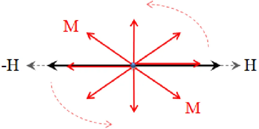
fluid’s frictional torques exerting on each MNP. This causes inflation in the measured viscosity denoted, in the literature, as rotational viscosity, Δη [1], [4]. Figure 1-1 depicts a representative rdMNP in planar (Couette or Poiseuille) flow subject to (+ x oriented) static magnetic field as explained by Shliomis [10] and Rosensweig [2]. It can be seen that the resulting (+ z oriented) magnetic torque acts in opposition to the (– z oriented) vorticity torque (i.e., mechanical torque). Obviously, magnetoviscosity would not manifest in ( z oriented) magnetic fields as M would be able to align with H without being bothered by vorticity.
Figure 1-1 : Steady-state illustration of typical rdMNPs subject to DC magnetic field in planar Couette or
Poiseuille flow. Deviation of magnetization from x direction is due to fluid vorticity [2], [10]
AC-field magnetoviscosity was first theoretically conceived by Shliomis and Morozov [4] and then experimentally investigated by Bacri et al. [11] and Zeuner et al. [28]. Ferrofluids are polarized linearly (i.e., with invariant direction) with an alternating magnetic field (figure 1-2) so that their rdMNPs would try to imitate the H pattern via gyration. In the motionless case, gyration transitions are racemic in the sense that the rdMNPs have two equiprobable choices to swing, either clockwise or anticlockwise, in a manner reminiscent of a metronome rhythm imposed by the alternating magnetic field. This entrains the average spin angular velocity per unit volume (p.u.v.) of ferrofluid to be in permanence zero, i.e., ω
= 0, with M being forced to transition across 0 in its quest in tracking H. In shear flows and provided (H(v)≠0), the rdMNP spin is partly orchestrated by the fluid vorticity which imposes its rotational direction, v, as the preferential direction. This biasing direction destroys symmetry between the two aforementioned equiprobable swing directions by privileging the one as illustrated in figure 1-3 and 1-4. Figure 1-3 depicts the rdMNP behavior of a Couette-Poiseuille flow in an AC magnetic field while the field is rising to maximum amplitude, and conversely figure 1-4, while the field is decreasing to zero [4].
Figure 1-2 : One cycle of AC-field oscillation
Shliomis and Morozov [4] view the “vorticity” slap on the rdMNP as the determining event for the initialization of rotation of the magnetization vector [in its quest for catching up the varying magnetic field]. We will denote the fluid vorticity (hydrodynamic) time scale as τh. They also view the characteristic time scale of AC magnetic field as equal to the Brownian relaxation time τB that is the characteristic time for which the magnetization vector is locked to the changing magnetic field. Assuming Re 1, they arrived at τB << τh which implies that the rotation of M, after its initiation by the vorticity slap, is relayed by the AC magnetic field. This nuances the role of fluid vorticity in the rotation of the rdMNPs as it only comes into play as a starter, each time H transitions through 0 (figure 1-2).
-1.5 -1 -0.5 0 0.5 1 1.5 0 1 2 3 4 5 6 H t(s)
One cycle of H oscillation
HIt has been shown theoretically [4] and later proven experimentally [11],[18] that low frequency (ΩAC, ΩACτB < 1) AC field inflates ferrofluid apparent viscosity, that is Δη > 0 and ω < ½|v|. When ΩACτB = 1, the magnetoviscous effect is nullified (Δη = 0) which is tantamount to ω = ½v or to cancelled friction torque between rdMNP and fluid mixture. High frequency magnetic fields (ΩACτB > 1) occasion energy transfers from the AC field to the fluid flow via rdMNP kinetic energy. It is this “oriented” energy transfer that decreases the apparent viscosity (Δη < 0; ω > ½|v|). Unlike what is shown in Figure 1-3 and 1-4, the mechanical torque exerted on the rdMNP is in opposite direction [4]. It is this phenomenon which is referred to as negative rotational viscosity in the literature.
Figure 1-3 : Schematic of MNPs exposed to AC magnetic field in plane Couette or Poiseuille flow in rising
Figure 1-4 : Schematic of MNPs exposed to AC magnetic field in plane Couette or Poiseuille flow in diving
part of the cycle. Deviation of magnetization from x direction is caused by fluid vorticity [4]
We have just seen that three characteristic times come into play in ferrofluid AC-field magnetoviscosity. Figure 1-5a-c highlight the three possible scenarios that might occur depending on the values of τB, τAC (= 1/ΩAC), and τh (= 1/|v|≈R/uRMS). Let us analyze the “rotational” fate of the rdMNP within one AC-field cycle. For case I (τB < τh < τAC, figure 1-5a), when H transitions across zero, Brownian agitation is capable of quickly randomizing the rdMNPs orientations because such reshuffling requires less time than the AC-field period. In addition, since τh < τAC, the breakage (with respect to fluid vorticity) is the most acutely felt by the rotating rdMNP when H is about to peak twice within each cycle, i.e., at its maximum and minimum values (figure 1-2). This breakage gives rise to positive rotational viscosity (Δη > 0). In case II (τB < τAC < τh, see figure 1-5b), Brownian agitation entails the same effect as in case I. However, remagnetization of the ferrofluid after it is Brownianly reshuffled (near H 0) follows a path similar to the one depicted above in the motionless situation, that is ω 0 when H is decreasing towards –H. This explains in part the occurrence in case II of ω < ½|v| and of the positive rotational
slow to disorganize the rdMNPs. In addition and unlike in the motionless situation, the vorticity slap is crucial at enabling all the rdMNPs to rotate at diapason to allow a gyrating magnetization vector to catch the oscillating magnetic field (figure 1-6). Since rdMNP rotation is locked to the frequency of the magnetic field, and this frequency being faster than fluid vorticity, therefore ω > ½|v| yielding negative rotational viscosity (Δη < 0).
Figure 1-5 : Impact on AC-field magnetoviscosity phenomena with respect to the relative order of Brownian,
hydrodynamic and AC characteristic times: a) τB > τh> τAC, ∆η>0; b) τB > τAC> τh, ∆η>0; c) τAC > τB> τh, ∆η<0
Figure 1-6 : Oscillating magnetic field causes synchronized rotation of rdMNPs when τAC > τB> τh
The rotating magnetic field (RMF) is generated using a two-pole three phase stator. The major character makes rotating-field magnetoviscosity distinguishable from AC-field
magnetoviscosity is the fact that in former case, neither magnetic field nor magnetization vector pass via zero point during a cycle. Thus, Ferrofluid magnetization vector (M) tracks
H regardless of the field frequency. Since there is no off-field moment, thermal agitation
mechanism not allowed destroying M by shuffling MNPs. As a result, synchronized rotation of rdMNPs is attainable even in low field frequencies. Following all given reasoning, one expects negative rotational viscosity in much lower frequencies rather than AC-field magnetoviscosity. Torque measurement experiments of ferrofluid exposed to RMF performed by MIT group (Rosenthal et al. [8], Rinaldi et al. [19], and He et al. [20]) declare that considerable negative rotational viscosity is achievable. These experiments show even negative apparent viscosity (η+∆η) < 0 at 50 Hz (96 Gauss field), 100 Hz (60 Gauss), 500 Hz (41 Gauss) using the same size of MNPs as used by Bacri et al. [11]. In literature, RMF magnetoviscosity modeled and treated exactly similar to AC-field magnetoviscosity following Shliomis and Morozov [4] approach. An argument on the puzzling huge frequency difference in negative rotational viscosity manifestation arises using AC-field or RMF is still lacking.
1.2.6 Ferrohydrodynamic transport equations
Solving the ferrohydrodynamic transport equations require embedding the physical concepts relating to Brownian relaxation, magnetization relaxation, and chiefly, magnetoviscosity, into conventional Newtonian non-magnetic fluid transport equations. This was accomplished by Shliomis [10] as explained in details by Rosensweig [2]. Magnetoviscosity entails the formulation of an internal angular momentum balance equation for the magnetic nanoparticles.
The conservation equation of ferrofluid linear momentum writes as:
2 0 ρ p μ ζ 2ζ μ λ μ ζ t u u u u ω M H u (11) (11)
Similarly, the conservation equation of ferrofluid internal angular momentum is:
2
where ρ is the fluid density, I is the moment of inertia per unit mass of MNPs, u is the linear flow velocity vector, ω is the spin velocity vector (i.e., average spin rate of all MNPs p.u.v. of ferrofluid [Erreur ! Signet non défini.]), p is hydrodynamic pressure, μ is the ynamic shear viscosity, λ is the dilatational viscosity, η' is the shear spin viscosity, λ' is the bulk spin viscosity, ζ is the vortex viscosity, and μ0 is the vacuum permeability. To get a better grasp on understanding equation 11 and 12, it is convenient to recall the physical meaning of each term.
Equation 11 RHS aggregates all the terms contributing to the production or consumption of linear momentum for polar fluid endowed with internal angular momentum. The vortex viscosity increment, , represents the effect of nanoparticles on mixture viscosity, in Newtonian suspension flows, regardless of their magnetic character or application of magnetic field [1],[2]. The next term in equation 11 points out that non-uniform spin velocity may induce linear momentum through vortex viscosity. The Kelvin body force term, μ0M.H, stems in situations where a spatially inhomogeneous magnetic field is exerted on incompressible ferrofluids. The last term in equation 11 is often dropped for incompressible ferrofluids, which is a common assumption.
The RHS first term in equation 12 derived from the divergence of spin gradient tensor stands for spin viscous diffusion between rotating MNP clumps (in the volume average sense) laying in the same neighborhood. The second term represents inter-conversion between internal and external angular momenta. Fluid vorticity represents the flow tendency to rotate free infinitesimal elements, such as MNP, while ω, the actual MNP spin rate, arises from the magnetic torque felt by the MNP. As a result, this coupling transfers angular momenta between MNP and ferrofluid. The magnetic body couple density, μ0M×H, stands for the magnetic torque exerted on the magnetic particles and driving their rotation. In some specified flow geometries, the MNP spin velocity vector field, appearing in the last term of equation 12, is assumed solenoidal [2],[21]. One such a geometry in which .ω = 0 occurs when the 2nd and 3rd terms of equation 12 RHS are collinear with fluid vorticity ½u vector as exemplified in figure 1-7 [22-24]. Fluid vorticity is parallel to y-direction before applying magnetic field as is also the case with μ0M×H when the field is enabled. As a result, ωx = ωz = 0 and ωy is only x dependent.
The ferrofluid continuity and conservation equations of the linear and internal angular momenta combined with one of the magnetization relaxation equations discussed in section
II.5, are in principle closed by adjoining the Maxwell equations. Maxwell’s equations
consist of the Gauß’s law for magnetic flux density and the (zero free-current density) Ampere’s law for magnetic field intensity, respectively:
0,
B H 0 (13)
Vector fields B, H and M are related through the well-known BHM constitutive equation:
M H
Bμ0 (14)
In equation 14, B and H are, respectively, total magnetic flux density and total magnetic field intensity in which both external field and induced field generated by (and felt within) ferrofluid are summed-up. Outside the ferrofluid domain, for instance in the non-magnetic surrounding material, the contribution of magnetization via BHM constitutive equation is marginal ( 0) with B and H only generated by the sources external to the non-magnetic material (i.e., including the ferrofluid magnetization contribution).
Figure 1-7 : Couette flows of ferrofluid confined between two parallel plates subject to magnetic field.
Adapted from [22]
z
x
y
V
z
ω
z
v
z
1.3 Application
1.3.1 Pipe flow momentum transfer
Further than the experiments performed in AC fields by Bacri et al. [11] and Zeuner et al. [18] to validate the magnetoviscosity theory, Schumacher et al. [25] aimed at investigating the effect of AC fields on pressure drop of ferrofluid pipe flow in laminar and turbulent regime. They also proposed a computational model based on ferrohydrodynamic theory and accompanied it with experimental data. Schumacher et al. [25] tested AC (in the [0-1] kHz range) magnetic field in the range [0 - 1264] Oe with a ferrofluid passing through 3 mm inner diameter tube. They defined the fractional pressure drop (fPd = ΔP(H)/ΔP(H = 0) - 1) merely as the relative variation of (downstream) pressure drop subject to H (inside solenoid) with respect to (upstream) pressure drop (outside solenoid, i.e., H = 0) over equal tube lengths and fully developed flows. As illustrated in figure 1-8, fPd was obtained for a range of Reynolds numbers covering laminar and transitional flow regimes. This figure highlights a strong dependence of fPd to flow rate. Based on the arguments discussed above regarding AC-field magnetoviscosity, fPd can take negative values (i.e., negative pressure drop) only if ΩACτB > 1. The maximum ΩACτB reached by Schumacher et al. [25] was 0.061 thus explaining why only fPd > 0 were reported coherent with expectation from theory. In the two sub-sections below we will try to summarize the modeling efforts by these authors regarding the ferrohydrodynamic models in laminar and turbulent pipe flows.
Figure 1-8 : Fractional pressure drop versus ferrofluid Reynolds number measured at different strengths of
400 Hz AC magnetic field. Adapted from [25]
Table 1 lists the parameters used by Schumacher et al. [25] in their ferrofluid flow simulations.
Table 1-1 : Parameters used in ferrofluid laminar and turbulent simulations [25]
Laminar Flow Model Turbulent Flow Model μ (Pa s) 3.85×10⁻³ 3.85×10⁻³ ρ (kg m-3) 1187.4 1187.4 ζ (Pa.s) 1.93×10⁻³ 1.93×10⁻³ η' (kg.m.s-1) 6.40×10⁻²⁰ 6.40×10⁻²⁰ C1 = ζ/ μ 0.5 0.5 C3 = η'/R2ζ 1.5×10⁻¹¹ 1.5×10⁻¹¹ Q (mL.min-1) 500 1400 H (Oe) 948 948 Ω (Hz) 60 60 τB (μs) 1.5 1.5 χ0 0.04 0.04 φ 0.025 0.025 0 0.02 0.04 0.06 0.08 0.1 500 1000 1500 2000 2500 3000 fP d Re 62.9 37.7 25.1 12.6
1.3.2 Ferrohydrodynamic laminar model
Schumacher et al. [25] solved the one-dimensional axisymmetrical laminar version of pipe flow ferrohydrodynamic model in which the continuity, the linear momentum (equation 11), the angular momentum (equation 12), and the magnetization relaxation (equation 7) equations were simplified into a set of four algebraic 2nd-order differential equations for solving the axial ferrofluid velocity component (u), the MNP spin rate (ω = ω), the axial pressure gradient (-dp/dz) and the magnetic torque density (MH) as a function of pipe radial coordinate, r. The following assumptions were made:
* (Pseudo)-steady-state flow, ∂/∂t = 0; * Axisymmetry, ∂/∂θ = 0;
* Fully developed flow for ferrofluid velocity and MNP spin rate, ∂u/∂z = 0, ∂ω/∂z = 0; * Ferrofluid flow is incompressible, i.e., .u = 0, which is also supported by the fully
developed flow assumption;
* In the absence of magnetic field, the spin rate vector ω is in θ direction. According to AC magnetoviscosity theory [4] summarized above, streamwise H oscillations constrain ω to keep along θ direction yielding .ω = 0 (i.e., ∂ω/∂θ = 0). This supports the above
axisymmetry assumption;
* The spatially uniform magnetic field entrains that M.H = 0 in equation 11;
* Viscous forces are dominant so that inertial effects in equation 11 are negligible as well as in equation 12 so that I(u.ω) = 0;
* By extension, inertial effects on transporting magnetization are also neglected in equation (7), u.M = 0. This is justified by the fact that in uniform magnetic field, magnetization spatial dependency is only due to velocity field gradient u which is perpendicular to u in the studied geometry.


![Figure 1-14 : Porous medium and flow details: Packed bed and magnetic field programming [30]](https://thumb-eu.123doks.com/thumbv2/123doknet/7541746.228444/54.918.178.700.112.465/figure-porous-medium-details-packed-magnetic-field-programming.webp)