HAL Id: hal-01796836
https://hal.archives-ouvertes.fr/hal-01796836
Submitted on 5 Mar 2019
HAL is a multi-disciplinary open access
archive for the deposit and dissemination of
sci-entific research documents, whether they are
pub-lished or not. The documents may come from
teaching and research institutions in France or
abroad, or from public or private research centers.
L’archive ouverte pluridisciplinaire HAL, est
destinée au dépôt et à la diffusion de documents
scientifiques de niveau recherche, publiés ou non,
émanant des établissements d’enseignement et de
recherche français ou étrangers, des laboratoires
publics ou privés.
A study of polymer-mold contact during injection
molding cycle
Maelle Guichon, Christine Boher, Fabrice Schmidt
To cite this version:
Maelle Guichon, Christine Boher, Fabrice Schmidt. A study of polymer-mold contact during injection
molding cycle. PPS 2005 -America’s regional meeting of the Polymer Processing Society, Aug 2005,
Quebec City, Canada. 2 p. �hal-01796836�
PPS 2005 Americas Regional Meeting Proceedings
An Understanding of Polymer/Mold Contact During Injection Molding Cycle.
M. Guichon1*, C. Boher2 and F. Schmidt3
1* [email protected]; 2[email protected]; 3[email protected];
Centre de Recherche Outillage Matériaux et Procédés (CROMeP), Ecole des Mines d’Albi-Carmaux, Campus Jarlard, route de Teillet, 81013 Albi, France.
Injection molded parts often show several types of surface defects. Different authors mentioned that those defects are due to the interaction between the mold and the melt. This contact has a strong influence on the flow front behavior, and depends on processing parameters like melt and mould temperatures, ram speed during injection, mould surface properties and roughness, mould thickness and polymer melt rheological properties …
After a literature review of “flow marks” defect, it appears that the “alternate flow marks” are caused by an instability of the Fountain flow front. An assumption proposed by some researchers is that the slip is the formation mechanism of this instability. We assume that this mechanism is the start of the flow front instability during the filling stage. We use numerical simulations performed with Forge2 commercial software, in order to generate non-symmetrical contact boundaries conditions. We introduce some sliding conditions at the wall during a flow between two parallel plates. Our preliminary computations confirm that the instability is created in this way.
Introduction
Injection molded parts often reveals several types of surface defects. These defects can appear under different forms on the surface of the parts. The general names of these defects are "flow marks", "tiger stripes", "ice lines", and "stick/slip defect". There is a mistake in the literature between the observation of these defects and their names. Yokoi [1] proposed a classification of the flow mark defects in three groups in terms of surface conditions: micro-grooved surface (also called micro flow marks, sharkskinning defect...); synchronous dull and gloss surface (also called halos for the parts injected by the center); alternate dull and gloss surface (called generally flow marks)
This last defect manifests itself as a regular pattern of oriented dull and shiny stripes more or less perpendicular to the flow direction [2,3]. Experiments performed by previous researchers suggest that the defect results from an unstable flow near the free surface [2,3,4,5,6,7]
Major studies of the filling stage consider that there is no slip at wall. Most authors mentioned that those defects are due to the interaction between the mold surface and the melt. This contact has a strong influence on the flow front behavior, and depends on processing parameters.
The instrumentation during the process is very difficult to implement, and give only partial results like pressure and temperature, but no real data about the contact formation.
Due to the limited availability of rheological data, there is no clear understanding of the rheological dependencies on the instability of the flow front. However, Chang [8] found that there is a link between the defects formation and the recoverable shear stress, and Xu [9] found that the rheological characterizations (like the storage and less modulus of the complex viscosity, the first normal stress difference, the
relaxation time...) have an influence on the defects formation. Thus, the molecular structure is having a strong effect on the elastic behavior of the polymer [8]. The aim of this paper is to investigate the assumption of the slip at wall for the mechanism of the flow front instability.
Numerical simulation
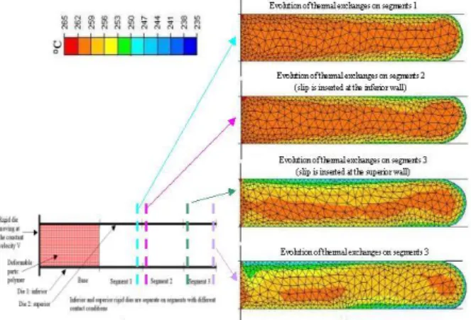
Using Forge2® software, we compute flow between parallel rigid dies with discontinuous and non-symmetrical contact conditions (figure1). Then, we investigate if flow front instabilities occur.
This software is a forming process simulation based on Finite Element Method (FEM). At each time step, the thermo-mechanical equations are solved in a weak form (Galerkin integral formulation). For non-linear constitutive equations , a Newton-Raphson algorithm is used to compute the resulting non linear algebraic system. Due to the updating Lagrangian’s procedure, an automatic remeshing procedure is used that allows to keep a fine mesh during flow computation (especially close to polymer flow front).
The polymer melt behavior is represented by a Norton-Hoff law with a Arrhenius type thermal dependence:
ij 1 m 0 T 0 ij 2K e 3 s (1)For numerical simulations, we use an ABS NOVODUR P2H-AT, for which rheological parameters are referenced in table1.
Table1 – Rheological parameters
m K0 (Pa.s) (°K)
0
(s-1) 0.3131 3437.19 7955.61 5.08044 In addition, we use a viscoplastic law (Norton type) to model the contact between polymer melt and rigid dies.
V V e K T m 1 0 (2)
PPS 2005 Americas Regional Meeting Proceedings Contact conditions are defined in figure1. The initial
temperature of the polymer and the die are respectively 206°C, and 20°C. Thermal exchanges between the polymer and dies are defined in figure1.
Results and Discussion
The conventional measuring methods cannot reveal the actual cause of flow marks, so Yokoi and al. have used particular visualization experiments to observe the flow inside the mold cavity. The defects seem to be due, in according to Bulters experiments [5], to an oscillatory flow between the cavity walls. We assume that this instability results from a discontinuity of the boundaries contact conditions. We investigate the slip boundaries condition to know if they may produce the instability.
Figure 2 – Computed polymer temperature using
non-symmetrical contact conditions (Forge2®).
In figure2, we note that a discontinuity of contact conditions can create an instability flow front behavior. The variation of the contact conditions generates non-symmetrical flow. When the slip is inserted at the cavity wall, the polymer swirls on the opposite cavity wall (when the slip is inserted at the inferior wall, the polymer swirls towards the superior wall). When the slip is changing at the other side, the polymer swirls on the opposite wall where there is the slip. We also find that the contact conditions influences the velocity profile (figure 2) in agreement with different experiments [9,10,11,12].
Yokoi [12] proposed the following mechanism for the formation of the flow marks:
- The polymer fractures/separates of one cavity wall
- This fracture creates the unsymmetrical flow - The region on the surface of the molded part,
where the polymer has fractured, forms a dull region (we observe it in figure 3)
Then, we assume that when the slip is inserted on a segment of cavity wall, it will create a dull region on the molded surface parts.
They revealed a temperature gradient between the glossy and dull region. Yokoi affirmed that the glossy regions are hotter and dull regions are colder. (figure 3).
Figure 3 – Thermal gradient temperature and
development of the dull and glossy regions [10] In our computations we observe a non-symmetrical gradient temperature created by the contact discontinuity (figure 2). This illustrates that when the polymer fractures/separates of the cavity wall, the temperature is low on the side where there has been the separation.
Conclusion
Using numerical simulations and specific contact conditions, we conclude that the slip at wall causes flow front instability during the filling stage.
Nevertheless, it is necessary to perform different numerical simulations using other polymers in order to confirm this result. In order to reproduce this defect, we will realize molded parts on an industrial injection machine.
We must verify slip hypothesis like a main mechanism of the formation of the surface defect by experimental means.
With all this considerations we can think that the sliding can be responsible of the surface defect. Nevertheless, note that we don’t know if this instability has been created by discontinuity of contact conditions (in practical) because Yokoi [12] and Chang [8] used a geometrical discontinuity with a insert near the gate on the thickness of the mold cavity and created by this way the same instability of the flow. Perhaps the two mechanisms are linked, the geometrical discontinuity can generate some sliding.
Whereas only a few simulations have performed to specifically investigate flow marks surface defects have been realized. And the extensional Fountain’s flow near the advancing free surface (where the stagnation point instability has been postulated) has already been investigated [14]. We investigated some numerical simulation under the software FORGE2. We investigated the slip to create the discontinuity boundaries contact conditions.
References
1. H. Yokoi, Y. Degushi, L. Sakamoto, Y. Murata, SPE ANTEC Tech. Papers, 1994, p.829
2. L. Mathieu, L. Stockmann, J.M. Haudin, B. Monasse, M. Vincent, J.M. Barthez, J.Y. Charmeau, V. Durand, J.P. Gazonnet, D.C. Roux, Int. Poly. Process., 2001,XVI-4, p.404
PPS 2005 Americas Regional Meeting Proceedings 4. H. Hamada, H. Tsunasawa, J. Apl. Poly. Sci.,
1996, 60, p.353
5. M.A. Bulters, A. Schepens, PPS 16 annual meeting Shangai China, june 18-23, 2000, p.144 6. M.C.O. Chang, SPE ANTEC Tech. Papers, 1994,
p.360
7. A.M. Grillet, A.C. Bogaerd, G.W.M Peters, F.P.T. Baijens, PPS 16 annual meeting Shangai China, june 18-23, 2000, p.148
8. M.C.O. Chang, Int. Poly. Process., 1996, XI-4, p.403
9. G. Xu, K.W. Koelling, SPE ANTEC Tech. Papers, 2001
10. H. Yokoi, PPS Annual Conference Presentation, 1994, p. 171
11. H. Yokoi, Y. Inagaki, SPE ANTEC Tech. Papers, 1992, 38, p.457
12. H. Yokoi, S. Kamata, T. Kanematsu, SPE ANTEC Tech. Papers, 1991, 37, p.358
13. M.C. Heuzey, J.M. Dealy, D.M. Gao, A. Garcia-Rejon, SPE ANTEC Tech. Papers, 1997, p.532 14. A.M. Grillet, A.C. Bogaerd, G.W.M Peters, F.P.T.