ÉCOLE DE TECHNOLOGIE SUPÉRIEURE UNIVERSITÉ DU QUÉBEC
THESIS PRESENTED TO
ÉCOLE DE TECHNOLOGIE SUPÉRIEURE
IN PARTIAL FULFILLMENT OF THE REQUIREMENTS FOR A MASTER’S DEGREE WITH THESIS IN AEROSPACE ENGINEERING
M. A. Sc.
BY
Mohamed Sadok GUEZGUEZ
MORPHING WING SYSTEM INTEGRATION WITH WIND TUNNEL TESTING
MONTREAL, JANUARY 28, 2016
© Copyright
Reproduction, saving or sharing of the content of this document, in whole or in part, is prohibited. A reader who wishes to print this document or save it on any medium must first obtain the author’s permission.
BOARD OF EXAMINERS
THIS THESIS HAS BEEN EVALUATED BY THE FOLLOWING BOARD OF EXAMINERS
Ms. Ruxandra Botez, Thesis Supervisor
Department of Automated Manufacturing Engineering at École de technologie supérieure
Mr. Christian Belleau, President of the Board of Examiners
Department of Mechanical Engineering at École de technologie supérieure
Mr. Franck Cazaurang, External Member of the jury Université de Bordeaux
THIS THESIS WAS PRENSENTED AND DEFENDED
IN THE PRESENCE OF A BOARD OF EXAMINERS AND THE PUBLIC 26 JANUARY 2016
FOREWORD
I would like to dedicate this work to my beloved parents who have raised in me the passion for knowledge and the ambition to achieve success. I wish I could thank them enough for the sacrifices they have always made to see me get to this day.
Secondly, to my sisters, who had never left my side and are very special. I am also thankful to all the members of my big family.
I dedicate this work to my friends and roommates who have given me advices, helped me to finish my project efficiently and encouraged me to work, a path that made me gain precious life experiences, which I would have missed otherwise.
ACKNOWLEDGMENTS
It is true that finalizing this master’s thesis was not an easy job which would not have been possible with no help. Writing the report had many ups and downs and, I would like to thank every person who has contributed in this work or helped me in a way or in another to finish it.
First of all, I would like to express my sincere gratitude to my research supervisor Dr Ruxandra Mihaela Botez for giving me the opportunity to work on this project among her team in very good conditions, and for her endless patience, guidance and support.
Secondly, my thanks go to Mr. Vincent Ruault, as we worked together on LARCASE, for his technical assistance and precious advices during the realization of my project.
I take to send my most sincere thanks to all the students and staff of LARCASE laboratory, special thanks to my colleagues Jean-Baptiste Vincent, Andreea Koreanschi, Oliviu Sugar-Gabor, Georges Ghazi, Alejandro Murrieta et Shahrayar Khan.
INTÉGRATION D’UN SYSTÈME D’AILE ADAPTABLE AVEC VALIDATION EXPÉRIMENTALE EN SOUFFLERIE
Mohamed Sadok GUEZGUEZ
RÉSUMÉ
Préserver l’environnement est un enjeu majeur de l’industrie aéronautique. Dans ce contexte s’intègre le projet CRIAQ MDO 505 qui est un projet multidisciplinaire international réalisé en collaboration entre des équipes canadiennes et italiennes. Les partenaires industriels sont issues des deux entreprises ‘Bombardier Aerospace’ et ’Thales Canada et Alenia Aermacchi. Les partenaires académiques proviennent de l’École de Technologie Supérieure, École Polytechnique de Montréal, Conseil National de recherche CNRC au Canada, Centre de recherche italien en aérospatiale (CIRA) et l’université de Naples.
L’objectif principal de ce projet est d’améliorer les performances aérodynamiques d’une aile à extrados flexible. En effet, on cherche à diminuer la trainée en retardant la transition de l’écoulement (du régime laminaire vers le régime turbulent) en optimisant la forme de l’extrados flexible dépendamment de la condition du vol. Le mécanisme conçu pour déformer la peau en composite est constitué de quatre axes linéaires actionnées par des moteurs ‘BLDC’. Les déplacements sont calculés par simulation numérique en fonction de la vitesse de l’écoulement, l’angle d’attaque de l’aile ainsi que l’angle de braquage de l’aileron. L’aile est aussi équipée de 32 capteurs de pression de type ‘Kulite’ afin de détecter expérimentalement la transition durant les tests en soufflerie, qui ont eu lieu, à l’institut de recherche en aérospatiale du CNRC à Ottawa.
Une première partie du travail réalisé consiste à établir les communications nécessaires entre le système de contrôle et les actionneurs de l’aile; Les protocoles de communication ‘CANopen’ et Modbus-TCP ont été implémentés. Une deuxième partie consiste à développer et valider expérimentalement une boucle de contrôle en position en se basant sur le retour des capteurs LVDT ainsi qu’une procédure automatisée de calibration des déplacements de la peau.
Deux sets de tests en soufflerie ont été effectués afin de tester les performances aérodynamiques de l’aile, ainsi que de la plateforme de contrôle mise en place. Les résultats de calibration obtenus ainsi que les résultats de contrôle du déplacement de la peau ont été bons par rapport à nos objectifs d’amélioration des performances. Une valeur maximale de 0.03 mm d’erreur statique, pour la boucle de contrôle en position, a été obtenue pour ses déplacements. L’analyse des données de pression, ainsi que les forces aérodynamiques mesurées par la balance de la plateforme de test, ont montré que la trainée a été diminuée pour 30% des cas de vol optimisés.
Mots-clés: aile, extrados flexible, protocole de communication, contrôle, calibration, trainée,
MORPHING WING SYSTEM INTEGRATION WITH WIND TUNNEL TESTING
MOHAMED SADOK GUEZGUEZ
ABSTRACT
Preserving the environment is a major challenge for today’s aviation industry. Within this context, the CRIAQ MDO 505 project started, where a multidisciplinary approach was used to improve aircraft fuel efficiency. This international project took place between several Canadian and Italian teams. Industrial teams are Bombardier Aerospace, Thales Canada and Alenia Aermacchi. The academic partners are from École de Technologie Supérieure, École Polytechnique de Montréal and Naples University. Teams from ‘CIRA’ and IAR-NRC research institutes had, also, contributed on this project.
The main objective of this project is to improve the aerodynamic performance of a morphing wing prototype by reducing the drag. This drag reduction is achieved by delaying the flow transition (from laminar to turbulent) by performing shape optimization of the flexible upper skin according to different flight conditions. Four linear axes, each one actuated by a 'BLDC' motor, are used to morph the skin. The skin displacements are calculated by ‘CFD’ numerical simulation based on flow parameters which are Mach number, the angle of attack and aileron’s angle of deflection. The wing is also equipped with 32 pressure sensors to experimentally detect the transition during aerodynamic testing in the subsonic wind tunnel at the IAR-NRC in Ottawa.
The first part of the work is dedicated to establishing the necessary fieldbus communications between the control system and the wing. The ‘CANopen’ protocol is implemented to ensure real time communication between the ‘BLDC’ drives and the real-time controller. The MODBUS TCP protocol is used to control the aileron drive.
The second part consists of implementing the skin control position loop based on the LVDTs feedback, as well as developing an automated calibration procedure for skin displacement values.
Two ‘sets’ of wind tunnel tests were carried out to, experimentally, investigate the morphing wing controller effect; these tests also offered the opportunity to validate the implemented control platform. Control and calibration results were excellent as they satisfied the desired objectives in terms of precision and robustness. The maximum static error obtained for the skin displacement control was 0.03 mm. The analysis of the pressure data and balance loads has shown that the drag was reduced for many cases among those tested. Almost 30% of the cases were optimized for drag reduction.
Keywords: morphing wing, flexible upper skin, fieldbus communication, control,
TABLE OF CONTENTS Page INTRODUCTION ...1 LITERATURE REVIEW ...3 CHAPTER 1 1.1 Morphing wing...3 1.1.1 Morphing concept ... 3 1.1.2 Benefits of ‘morphing’ ... 4 1.1.3 Morphing skins ... 4 1.2 CRIAQ 7.1 Project ...5 1.2.1 Morphing mechanism ... 6
1.2.2 Control system architecture used with wing morphing ... 7
1.2.3 Control method used for morphing wing ... 9
1.3 CRIAQ MDO 505 Project ...9
1.4 Fieldbus ...10
1.5 CAN and CANopen communication protocol ...11
1.5.1 CAN bus... 12
1.5.2 CANopen communication protocol ... 13
1.5.2.1 Object Dictionary ... 14
1.5.2.2 Service Data Object (SDO) ... 15
1.5.2.3 Process Data Object (PDO) ... 15
1.6 MODBUS communication protocol ...16
1.6.1 Overview ... 16
1.6.2 MODBUS protocol variants ... 16
1.6.3 MODBUS TCP/IP ... 17
1.7 Aerospace Communication protocols ...17
1.8 Digital PID control ...18
CHAPTER 2 MORPHING WING SYSTEM: OVERVIEW AND ARCHITECTURE ...19
2.1 Morphing wing model description ...19
2.1.1 Wing description ... 19
2.1.2 Model Morphing Mechanism ... 20
2.2 Wing control system setup ...21
2.2.1 Real time controller NI PXI-e 8135 ... 21
2.2.2 Fieldbus communications ... 23
2.2.3 EPOS2 24/5 drives ... 23
2.3 System Software Setup ...25
2.4 CANopen communication protocol implementation: Application to the EPOS2 24/5 drives ...27
2.5 Modbus TCP/IP communication protocol implementation: Application to the Kollmorgen® drive ...38
2.5.2 Modbus TCP implementation ... 39
WING SHAPE MORPHING ...43
CHAPTER 3 3.1 Wing morphing in open loop ...43
3.1.1 Skin shape open loop control ... 43
3.2 Skin shape closed loop control ...48
3.2.1 Principle of the closed loop... 48
3.2.2 Closed loop implementation: ... 49
3.2.3 Closed loop model structure and execution ... 50
3.2.4 Adjustment of the closed loop parameters ... 51
3.3 Skin shape morphing using lookup tables ...54
3.3.1 Principle of ‘lookup tables’:... 54
3.3.2 Open loop measurements ... 55
3.3.3 Measurements analysis ... 58
3.4 Skin shape morphing using feedback on DDI ...59
3.4.1 Principle of the closed loop on DDI ... 59
3.4.2 Retrieving displacement values from DDI ... 61
3.4.3 DDI closed loop implementation ... 64
3.4.4 Optimization of the wing shape for one flight condition ... 67
3.5 Flight case calibration procedure ...69
3.5.1 Principles of flight case calibration ... 69
3.5.2 Models’ mutual interaction during flight cases calibration ... 71
3.5.3 Automating the calibration procedure: ... 72
3.6 Skin shape morphing using system identification ...74
3.6.1 Principle ... 74
3.6.2 Data collection ... 75
3.6.3 Model integration and implementation ... 75
Wind Tunnel Tests and Results ...77
CHAPTER 4 4.1 Wind Tunnel Tests ...77
4.1.1 NRC-CNRC wind tunnel description ... 77
4.1.2 Preparation and performance of the tests ... 79
4.2 Results ...82
4.2.1 Wing shape morphing using lookup table results ... 82
4.2.2 Wing shape morphing using calibration results ... 84
4.2.3 Overview of aerodynamic results ... 90
CONCLUSION ...101
RECOMMENDATIONS ...105
ANNEX I Morphing mechanism ...107
ANNEX II NMT slave state ...109
XV
ANNEX IV Modes of operation ...115
ANNEX V RxPDOs and TxPDOs addresses ...117
ANNEX VI SDOs programming sequence for EPOS2 drives ...119
ANNEX VII Detailed results for skin displacements control using Lookup tables method...127
ANNEX VI I Kollmorgen® drive parameters ...129
ANNEX IX Actuators displacement profiles ...131
ANNEX X Aerodynamic comparison ...133
LIST OF TABLES
Page
Table 2.1 Software environment description ...27
Table 2.2 Nodes identifier mapping ...29
Table 2.3 Node-ID calculation ...29
Table 2.4 Mapping of the ‘Statusword’ and ’Actual position value’ of node ID ‘1’...37
Table 3.1 Measurements (in mm) used to determine actuator offset values ...45
Table 3.2 First measurement set ...56
Table 3.3 Second measurement set ...57
Table 3.4 Database organization ...68
Table 3.5 Training data organization ...75
Table 4.1 Wind tunnel technical specifications Adapted from National Research Council Canada (2013) ...79
Table 4.2 Comparison between IR transition detection and numerical transition prediction during the first WTT campaign ...94
LIST OF FIGURES
Page
Figure 1.1 The mechanical principle of morphing ...6
Figure 1.2 Sensor acquisition system in the SMA control architecture ...8
Figure 1.3 SMA current control architecture ...9
Figure 1.4 Communication protocols in an automation pyramid ...11
Figure 1.5 Open System Interconnection (OSI) seven-layer reference model ...12
Figure 1.6 CANopen device model ...14
Figure 1.7 TPDO and RPDO ...15
Figure 2.1 Wing structure overview ...20
Figure 2.2 Overview of the morphing mechanism without the upper skin ...21
Figure 2.3 Overview of the wing control system and adopted communications between its components ...22
Figure 2.4 Basic internal architecture and interfaces of the EPOS2 24/5 ...24
Figure 2.5 EPOS2 24/5 position regulation structure...25
Figure 2.6 NI-VeriStand® project ...26
Figure 2.7 CANopen network structure ...28
Figure 2.8 DIP Switch-CAN Bus termination...29
Figure 2.9 Position Mode Flowchart ...30
Figure 2.10 Drive configuration and initialization sequence ...35
Figure 2.11 Aileron control program diagram ...42
Figure 3.1 Skin response with open loop position control ...44
Figure 3.2 Actuator ‘1’ displacement profile ...46
Figure 3.4 Principle of the position closed loop based on the LVDT feedback ...48
Figure 3.5 Data flow diagram for the closed loop control position on the LVDT ...49
Figure 3.6 Position control model structure of the closed loop on the LVDT ...50
Figure 3.7 Position control loop detailed architecture ...52
Figure 3.8 Mechanical latency of the actuator ...53
Figure 3.9 Actuator responses for different proportional gains ...54
Figure 3.10 Principle of Lookup table...55
Figure 3.11 Skin displacement versus LVDT measurements for the actuator ‘1’ ...58
Figure 3.12 Position closed loop on digital dial indicators ...61
Figure 3.13 Data flow diagram between digital indicators and the PXI-e ...61
Figure 3.14 Reading digital indicators values diagram ...63
Figure 3.15 Data flow diagram for closed loop control position on LVDT ...64
Figure 3.16 Position control model structure of the DDI closed loop ...65
Figure 3.17 Skin response with closed loop on digital indicator without taking into account the proportional controller ...66
Figure 3.18 Response of the closed loop after adding the proportional controller ...67
Figure 3.19 Digital Dial Indicators installed on the wing for calibration during WTTs ...70
Figure 3.20 Simplified models communication diagram ...71
Figure 3.21 Calibration execution diagram ...73
Figure 3.22 Principle of the artificial neural network system ...74
Figure 3.23 ANN system integration ...76
Figure 4.1 Simplified scheme of the wind tunnel at NRC ...78
Figure 4.2 Wind tunnel control room, test section and balance room plan ...80
XXI
Figure 4.4 Error distribution by flight case for the actuator ‘2’ ...83
Figure 4.5 Error distribution by flight case for the actuator ‘3’ ...83
Figure 4.6 Error distribution by flight case for the actuator ‘4’ ...83
Figure 4.7 Measured skin displacement error for each flight case during calibration ...85
Figure 4.8 Measured error on LVDT during the validation of calibration results ...86
Figure 4.9 Cumulative errors of the skin displacement control using the calibration method ...87
Figure 4.10 Errors obtained during WWT calibration of four actuators ...87
Figure 4.11 Displacement’s error amplitude measured on LVDTs during Wind Tunnel Tests ...88
Figure 4.12 Calibration error percentages for each actuator ...89
Figure 4.13 Power spectrum of Kulite sensors for a morphed configuration ...91
Figure 4.14 Standard Deviation (STD) of pressure data for all channels ...92
Figure 4.15 Infrared picture of the wing upper surface with a morphed configuration ...93
Figure 4.16 Comparison of the transition with different detection methods for the non-morphed wing ...97
Figure 4.17 Comparison of the transition with different detection methods for the morphed wing ...98
LIST OF ABREVIATIONS
BLDC Brushless Direct Current CAN Controller Area Network CANopen Open Controller Area Network COB-ID CAN object identifier
COM Serial Communication Port
CRIAQ Consortium for Research and Innovation in Aerospace in Quebec
DAQ Data Acquisition
DDI Digital Dial Indicator
DFT Discrete Fourier Transform EDS Electronic Data Sheet
EPOS Easy to use Positioning System ÉTS École de Technologie Supérieur FFT Fast Fourier
IAR Institute for Aerospace Research
ID Identification Number
LARCASE Research Laboratory in Active Controls, Avionics and Aeroservoelasticity LVDT Linear Variable Differential Transducer
NI National Instruments
NMT Network Management
NRC National Research Council Canada
OSI Open System Interconnection PDO Process Data Object
PID Proportional Integrator Derivative PLC Programmable Logic Controller RPDO Receive Process Data Object SDO Service data object
SMA Shape Memory Alloy STD Standard Deviation
TCP/IP Transmission Control Protocol/ Internet Protocol UAVs Unmanned Aerial Vehicles
UDP User Datagram Protocol
USB Universal Serial Bus WWTs Wind Tunnel Tests
1
INTRODUCTION
Passenger air traffic is continuously increasing around the world; some predictions indicate that 3.6 billion passengers will fly in 2016 (Green Aviation, 2010). Such a level of air traffic could be harmful to the environment given the number of flights required to fulfill the market needs. Preserving the environment is a major challenge for the aviation industry, for all of those involved in the aeronautical world. A number of research programs have been established to reduce, as much as possible, the impact of the aircraft industry on the environment (Green Aviation (2010), Popov et al. (2009) and Sugar Gabor et al. (2015)). A major focus of these research programs is the airframe technology, as it affects aircraft structure weight, aerodynamic performance, fuel consumption and noise.
Within this context, the multidisciplinary international project CRIAQ MDO 505 began in 2012 between Canadian and Italian teams. The academic team members were from École de technologie supérieure (ETS), École Polytechnique de Montréal, Canada's National Research Council (NRC), Bombardier Aerospace and Thales Canada. Two other Italian teams from the university of Naples Federico II and CIRA are also present in this project. The leader of this project is my research supervisor Dr Ruxandra Botez, director of the LARCASE Laboratory, at ETS.
The goal of the CRIAQ MDO 505 project is to reduce the drag effect on aircraft, thus the fuel consumption, through an innovative flow control concept. The upper skin of the wing will be morphed depending on the flight conditions, thereby delaying the laminar to turbulent flow transition. The control of the transition is expected to have significant economic and environmental benefits (improved aircraft energy efficiency, lower CO2 emissions and
reduced noise).
Within this project, a wing prototype with a carbon fiber reinforced flexible upper skin is designed and fabricated. This wing has an integrated morphing mechanism, an actuated aileron and pressure sensors (32 Kulite sensors) distributed chordwise. Controlling the wing
morphing system, including pressure data acquisition and aileron deflection, are among the responsibilities of our research laboratory, the Research Laboratory in Active Controls, Avionics and Aero-Servo-Elasticity, LARCASE. A complete control system was integrated, tested and used during wind tunnel tests performed in the IAR-NRC’s subsonic wind tunnel in Ottawa.
The focus of this thesis is to present our realizations within this project. It consists of the hardware/software integration and the control of the wing upper skin shape.
We start by reviewing the general morphing principle, morphing mechanisms and main control methods. We then present fieldbus communication, focusing on two specific protocols (CANopen, Modbus TCP) that are used for the communication with our wing actuators. Both protocol principles and their implementation details are explained.
In the second chapter, we offer a detailed description of the wing structure, including the inbox morphing mechanism as well as its control system components. A main part of our work was the implementation of communication protocols; the communication with the morphing mechanism drives is presented and demonstrated, followed by a description of another communication protocol used for the aileron.
We then dedicate an entire chapter to detail the method developed for controlling the skin displacement within a very high precision. Because of the need to address several abnormal issues during our first attempt to optimize the skin shape, we present the methods adopted to solve each issue, from the closed loop for actuator motion control to the automated calibration procedure. The last chapter covers the wind tunnel tests performed at the IAR-NRC in Ottawa, and then presents the results obtained during those tests (The controller results as well as aerodynamic improvements).
CHAPTER 1
LITERATURE REVIEW
1.1 Morphing wing
1.1.1 Morphing concept
The simplicity, the elegance and the efficiency of flight in nature have always inspired researchers and aircraft designers, especially in terms of the link between the structure and function characterizing the wings of birds (Bowman, Sanders et Weisshaar, 2002) and (Barbarino et al., 2011)).
The ability of birds to change their wing shapes according to each specific flight task lead to the idea of aircraft wings shape modification. Indeed, Mujahid et Lind (2006) worked on the avian morphology principle that makes possible the use of specific wing configurations for every type of flight.
As aircraft have been designed to support important loads, their structures are unable to adapt to aerodynamic conditions change. Newer aircraft designs have underscored the need for a morphing wing and other components configurations during their flights (Stanewsky, 2001).
Morphing has therefore been defined in the aerospace field as “a set of technologies that increase a vehicle’s performance by manipulating certain characteristics to better match the vehicle state to the environment and task at hand”(Weisshaar, 2006).
The ‘history of morphing’ as described by Weisshaar (2006) shows that there were some problems associated with morphing solutions, such as cost, complexity and weight, but that they could be overcome by the use of SMART materials (Chopra, 2002). Shape modification
methodologies have also been developed, firstly for military applications and then for reduced scale aircrafts such as Unmanned Aerial Vehicles (UAVs).
Changing or morphing the shape of a wing requires actuators, internal mechanisms and sliding aerodynamic surfaces (Inman, 2001). The way in which shape is changed (morphed) and at which speed, the control methodology and the sensor implementation are all fundamental morphing design elements.
1.1.2 Benefits of ‘morphing’
Morphing technology offers numerous advantages for both military and civil aerospace fields; it ensures improved aerodynamic performance during cruise along with reduced fuel consumption, and thus costs. For military applications, a single morphing wing can perform different missions allowing the aircraft to widen its flight envelope and be able to have multi-role capabilities that, otherwise could require different aircrafts (Barbarino et al., 2011).
1.1.3 Morphing skins
An efficient flexible skin is the key for many morphing concepts; however, its design remains challenging. The skin has to respond to different requirements: it must not only be soft enough to allow the shape changing, but it must also be stiff enough to support the required aerodynamic loads, all while maintaining the needed shape/profile (Barbarino et al., 2011).
Each application has its own specific loading scenario and shape changing requirements which directly influence the design of the flexible skin. Many different materials have been tested (Thill et al., 2008), and different solutions have been considered (Wereley et Gandhi, 2010) in the design of morphing skins with the aim to satisfy the various requirements.
5
Numerous research studies have been focused on optimizing the shape of the wing airfoil that affects the transition between laminar and turbulent flows, as a turbulent flow has a major negative effect. An increase in the drag causes more fuel consumption and therefore increasing costs. Indeed, the research realized by the LARCASE team under the supervision of Dr Ruxandra Botez within the scope of several different research projects, have produced notable results.
Projects such as the optimization of the ATR42 aircraft airfoil ((Sugar Gabor, Koreanschi et Botez, 2012), (Koreanschi, Sugar Gabor et Botez, 2015)) and the Hydra Technologies S4 Unmanned Aerial System (UAS) airfoil (Sugar Gabor et al., 2015), obtained notable transition delays of up to 20% of the chord, thus, reducing the total drag by 15%. These morphing systems has led to the improvements of aerodynamic performances for high angles of attack ((Sugar Gabor, Koreanschi et Botez, 2015) and (Sugar Gabor, A. Koreanschi et R. M. Botez, 2013)) .
1.2 CRIAQ 7.1 Project
CRIAQ 7.1 is a multidisciplinary project realized within collaboration between ETS-LARCASE team, ‘École polytechnique de Montréal’ and the National Research Council Canada Institute for Aerospace Research (NRC-IAR). It has been funded by the Consortium for Research and Innovation in Aerospace in Quebec (CRIAQ), the National Sciences and Engineering Research Council of Canada (NSERC), Bombardier Aerospace and Thales Canada.
The aim of the project was to improve the aerodynamic performance of a morphing wing prototype by changing the upper skin shape according to the desired flight condition. The rectangular wing was equipped with a flexible skin, smart actuators and optical sensors, and could change its shape through an active controller. Next, theoretical and experimental wind tunnel studies of the system were realized in order to validate the adopted control method and
to ensure the accurate transition displacement toward the trailing edge for aerodynamic performances increase (Popov, 2010).
A description of some aspects of this work is given below, including the morphing mechanism, the control system architecture and the deployed methodology.
1.2.1 Morphing mechanism
The morphing mechanism considered in the CRIAQ 7.1 project was described by Popov et
al. (2009). The authors developed a closed control system in order to ensure the connection
between the flow fluctuations located over the wing surface and the actuators which were used for the morphing operation. Kulite sensors, which are conventional pressure transducers, were used for the detection of flow fluctuation signals. By utilizing a real time data processing, it was possible to determine the transition location, so that a signal could be sent to the actuators to modify the wing surface, and thereby delay the transition location.
Figure 1.1 The mechanical principle of morphing Popov et al. (2009)
7
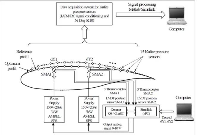
The capability of Kulite transducers to detect small pressure variations was tested on a morphing wing in a subsonic wind tunnel at the IAR-NRC. A rectangular wing model composed of two different parts constitutes the ‘morphing wing’ model shown in Figure 1.1. The first part, made of aluminum, is fixed and supports the resistance forces acting during the tests. The second part is a flexible skin added on the upper surface of the wing which changes its shape according to two actuation points to realize an airfoil optimized for each test airflow condition. Two shape memory alloy actuators (SMA) were used to create the displacements of the two control actuation points. Fifteen Kulite transducers were installed on a diagonal line at 15 degrees to the center line of the wing, numbered from the location nearest to the leading edge (#1) to the one nearest to the trailing edge (#16).
Popov, Grigorie et Botez (2009) provided a detailed description of the SMA actuators. As indicated in Figure 1.1, two oblique cam sliding rods compose the actuators designed to convert the motion from horizontal along the span to perpendicular along the chord. The equilibrium between the SMA wires pulling the sliding rod in the reverse direction gives each actuator its position. When SMAs are inactive, gas springs are added to counteract the pulling effects caused by the aerodynamic forces acting in the wind tunnel. The whole model was vertically installed in the wind tunnel. Runs were then performed for different airflow conditions including the angle of attack and Mach number.
1.2.2 Control system architecture used with wing morphing
Popov, Grigorie et Botez (2009), used a specific control system architecture that was very important for implanting the bench test and for obtaining of the different experimental results in the wind tunnel. The flexible wing skin was designed and manufactured by the LAMSI team at ETS to ensure the modification of its shape accordingly to the two action points, thereby obtaining the optimized airfoils for the various airflow conditions.
Each SMA actuator had six wires powered by two AMREL SPS power supplies and controlled by a QUANSER Q8 control board via analog signals. The Q8 control board was
programmed in Simulink/xPC language using an interface that allowed the user to specify the optimized airfoil shapes and the values required for the SMAs displacements. Popov et al. (2010) introduced details on the sensor acquisition systems developed in the SMA control architecture. Figure 1.2 shows that the acquisition of the pressure data was achieved by use of a NI-DAQ USB 6210 card with 16 analog inputs having a total sampling rate equal to 250 KS/s. The IAR-NRC analog data acquisition system was connected on one side to the input channels and on the other side to the 15 Kulite transducers. An extra channel was used, not only for dynamic pressure acquisition in the wind tunnel, but also for the pressure coefficient calculation from the measured pressure values. The signal processed in Simulink was displayed in real time.
Figure 1.2 Sensor acquisition system in the SMA control architecture Popov et al. (2010)
9
1.2.3 Control method used for morphing wing
In addition to the importance of the control system architecture described above, the control method used for the tests played a significant role, as it affected the entire system behavior. Popov, Grigorie et Botez (2009) proved that for each SMA actuator, there was a controller keeping it in the desired position. Figure 1.3 illustrates the controller concept composed of a PID and a switch, allowing the connection and the disconnection of the SMA actuator to a current source to heat and then to let the SMA cool, allowing it to change its length. Another method, self-tuning using fuzzy logic, has also been tested and applied to SMA control (Popov et al., 2010).
Figure 1.3 SMA current control architecture Popov, Grigorie et Botez (2009)
1.3 CRIAQ MDO 505 Project
The studies and experiments in the CRIAQ MDO 7.1 project have led to a significant improvement of the prototype aerodynamic performance; drag reduction of as much as 30 % has been achieved (Mamou et al., 2010). In the same context, the CRIAQ MDO 505 project entitled ‘Morphing Architectures and Related Technologies for Wing Efficiency Improvement’ had the same goal as its predecessor project (CRIAQ MDO 7.1), but used another prototype; this prototype had with real wing tip dimensions and structure. The main concept of this project is to improve the aerodynamic performances of a wing demonstrator at low subsonic speeds by optimizing the pressure distribution, and by extending the laminar flow on the upper skin. The demonstrator is a wing-tip section which consists of a main wing
box and an aileron. Design, manufacturing and aerodynamic tests were carried out over a period of three years. The wing model, equipped with a flexible composite skin, was tested with a rigid aileron, and then a morphing aileron was considered. The design and manufacturing of the morphing aileron took place in Italy, with the participation of Naples Frederico University II, Alenia and CIRA (the Italian Aerospace Research Center). The integration of the morphing aileron with the morphing wing was performed at the NRC in Ottawa during the last tests phase of the project. This thesis was realized within the CRIAQ MDO 505 project.
1.4 Fieldbus
The traditional method for connecting field-mounted devices to the inputs and outputs of a control system or a PLC (programmable logic controller) involves an overwhelming amount of wiring and connections (Blevins et Nixon, 2010). Technological improvements have led to more intelligent devices (motor drives, intelligent sensors) with embedded microcontrollers which should be able to intercommunicate and exchange data during complex control and automation operations (Ayre et Keydel, 2003). The need to replace traditional cabling and improve access to distributed information led to the introduction of Fieldbus communication (Dietrich et Sauter, 2000).
The typical definition of fieldbus is that it is ”a network for connecting field devices such as sensors, actuators, field controllers (such as PLCs, regulators, drive controllers…) and man– machine interfaces” (Thomesse, 2005). Nowadays, many different fieldbus-based communications protocols are used in industries, most of which are defined by international
standards (AS-Interface, CAN (Controller Area Network), CANopen, EtherCAT, MODBUS,
FOUNDATION-fieldbus, Profibus, etc).
We focus here on the description of two protocols (CANopen and MODBUS) as their implementation is required for our project.
11
Figure 1.4 Communication protocols in an automation pyramid
Adapted from Ayre et Keydel (2003)
The Automation pyramid in Figure 1.4 shows the different control levels and the architecture of a typical automation system. The CAN, which is the basic layer of the CANopen protocol, and MODBUS protocols are present among the three lower levels among five levels; the first level contains the sensors (contact sensors, distance and pressure sensors) and actuators (electric motor, hydraulics, etc). The second level is ‘the controller coupler level’ which implements directly the control loops between sensors and actuators (Ayre et Keydel, 2003). The process control level contains the high-end-controllers, such as PLCs, and embedded real time controllers (PXI-e of NI as an example), which could be connected to low-level distributed controllers on the controller coupler level.
1.5 CAN and CANopen communication protocol
The standardized communication protocol CANopen is a higher-layer protocol (Figure 1.5) based on the CAN protocol, used for industrial embedded networking. Before going into the basics of CANopen, an overview of the CAN protocol is helpful in order to have a better understanding of the CANopen communication protocol.
Figure 1.5 Open System Interconnection (OSI) seven-layer reference model
Taken from Ayre et Keydel (2003)
1.5.1 CAN bus
CAN is a serial communication bus protocol that uses a unique bus access control method called ‘Nondestructive Bitwise Arbitration’. “It supports distributed real-time control with a very high level of security” as mentioned by Sunit K . Sen (2014a). CAN was officially introduced by Bosch in 1986 and was intended to satisfy the high demand for electronic control systems in the automotive industry (Sunit K . Sen, 2014a).
CAN only implements the two lower levels of the Open System Interconnection (OSI) seven-layer model, the ‘Data link seven-layer’ and the ‘Physical Layer ‘out of 7 seven-layers (Figure 1.5). The ‘data link layer’ is responsible for packaging the received data (from the physical layer) in ‘frames’. The physical layer provide the connection of the data link layer (the CAN controller) to the physical medium (transmission medium), as it contains the CAN transceiver. The CAN transceiver has a double role, as it also converts the received signals (from the CAN controller) to a differential signal between the two wires of the network cable, are refereed as CAN_L and CAN_H (Ayre et Keydel, 2003).
13
A typical CAN bus consists of a twisted pair cabling with termination resistors (120 Ohm) on each side, and nodes that are connected through CAN_H and CAN_L signals(Ayre et Keydel, 2003). The use of differential signal bus makes the CAN bus very robust to external noise, thus any electromagnetic interference (EMI) is avoided. CAN bus speed can achieve 1 Mbit/s for a bus length less than 45 meters, however the bit rate decreases with the bus length(Ayre et Keydel, 2003).
A variety of higher layer protocols were developed based on CAN, such as CANopen and DeviceNet. The basics of the CANopen application layer are presented next.
1.5.2 CANopen communication protocol
CANopen is a standardized communication higher-layer protocol, implemented through the higher layers of the OSI seven-layer model. Many communication/networking technologies lack a dominant higher layer protocol standard; they only offer data transmission and reception functionalities without any specification regarding the data type or the number of messages streaming over the network (a sort of layer 2 (Data link layer) interface) (Ayre et Keydel, 2003).
In the CANopen protocol, the following parts of the higher layers (Figure 1.5) are implemented (Ayre et Keydel, 2003):
• network layer: destination addressing and routing via Service Data Object (SDO) channels, interaction functionality between a host and the network (configuration via SDO objects, etc.);
• transport layer: provides communication reliability between source and destination (provided by Network Management (NMT) services);
• session layer: defines functions, such as ‘write access’ to a shared database record (SDO channel management) and synchronization; and
• Presentation layer: involves data representations in a standardized way (Object dictionary, etc.).
Figure 1.6 CANopen device model Adapted from CAN in automation (2011)
A typical CANopen device model is represented in Figure 1.6. The device has three function units (CAN in automation, 2011):
• Communication function unit : provides the link between the object dictionary and the data transportation support, which is the network;
• Object dictionary; and
• Application function unit: ”the application comprises the functionality of the device with respect to the interaction with the process environment” (CAN in automation, 2011). The terms SDO, NMT, and Object Dictionary are related to the CANopen protocol and will be defined in the following subsections.
1.5.2.1 Object Dictionary
The object dictionary is the core of any CANopen device. It is a table of objects with a 16-bit index and an 8-16-bit sub-index. Node information and configuration is stored in the object dictionary. All the processes and data used by the application will also be stored as entries
15
with predefined addresses. Within the object dictionary it is possible to define the data types for each assigned variable, and to configure a node and modify its parameters by writing to the object dictionary related to that node (CAN in automation, 2011).
1.5.2.2 Service Data Object (SDO)
Since each node can implement its own object dictionary (OD), it can also implement a server for reading and writing access to that object dictionary. SDO is a direct method to access an OD using the ‘Client and server’ communication type (Ayre et Keydel, 2003). This method is especially useful during the initialization phase of a CANopen-based communication session, as it allows the network master to initialize and configure other nodes. There are two types of SDO objects, ‘SDO read’ which implement a read access and ‘SDO write’ which implements a write access. While it is possible to build an entire communication system by only using SDOs, for real-world real time implementation, the Process Data Object (PDO) method is preferable.
1.5.2.3 Process Data Object (PDO)
Figure 1.7 TPDO and RPDO Adapted from Ayre et Keydel (2003)
Process Data Object provides a fast way to send real time data with a high priority. The maximum data that can be sent in a PDO structure is 8 data bytes. Each PDO is transmitted by only one node and has a unique identifier. We distinguish two types of PDO, the Transmit Process Data Object (TPDO) and the Receive Process Data Object (RPDO). When a node produces a PDO, it is considered as a TPDO for this node. For a node that receives or consumes this process data object, the PDO is an RPDO.
1.6 MODBUS communication protocol
1.6.1 Overview
MODBUS is a standardized serial communication protocol widely used in the automation industry for equipment supervision and control. This messaging structure was created by AEG-Modicon (an American company specialized in automation that is now part of Schneider Electric) for use on industrial Programmable Logic Controllers (PLCs) in 1979. It is used in multiple master-slave /client-server applications, enabling the communication between intelligent field devices and embedded controllers or PLCs (Modbus Organization, 2015).
Today, MODBUS is an open protocol which implements the application layer messaging protocol of the Open System Interconnection (OSI) model (Sunit K . Sen, 2014b). From a practical point of view, MODBUS does not require any kind of special interfaces as the CANopen protocol for example, and can be used over the Ethernet as well as with serial cables.
1.6.2 MODBUS protocol variants
There are typically three variants of MODBUS protocols: • ASCII (the original version);
17
• RTU; and • TCP/IP .
MODBUS ASCII and MODBUS RTU protocols are used with serial communication, but they are two distinct transmission modes (Sunit K . Sen, 2014b) could be consulted for further details). Three electrical interfaces may be used with MODBUS RTU devices which are the most common implementation and they are RS 232, RS 485, and RS 422.
1.6.3 MODBUS TCP/IP
MODBUS TCP is a variant of the MODBUS protocols that specifically covers the use of MODBUS messaging in an ‘Intranet’ or ‘Internet’ environment using the TCP/IP protocols (Swales, 1999).
MODBUS TCP/IP offers several advantages as seen in Sunit K . Sen (2014b) and Modbus Organization Inc (2006):
• simplicity: minimum hardware is required and it is exceptionally low-cost;
• Standard Ethernet: a standard PC Ethernet card can communicate with MODBUS TCP/IP devices. It also uses standard Ethernet cables and switches to send messages; and
• openness: it has been an open protocol since 1999.
MODBUS TCP/IP devices use Internet Protocol (IP) addressing and require a subnet mask (Sunit K . Sen, 2014b) as follows:
• IP address : “000.000.000.000” (personalized by the user); and • Subnet mask: “255.255.255.255” (default value).
1.7 Aerospace Communication protocols
Data buses are a key element of any ‘Fly by wire’ aircraft control system. These networks offer many benefits to the aeronautical industry, such as reduction of the amount of wiring and thus the total aircraft weight, simple system integration as well as greater reliability and improved performance. Communication protocols on aircraft should be completely safe and
reliable; they ensure the transmission of critical data between sensors, actuators and aircraft control computers (Alena et al., 2007). Several communication protocols for avionics have been developed, among theme we can mention ARINC 429, MIL-STD 1553B, CAN, TTP and AFDX (ARINC 664). For further details regarding these protocols, please see Alena et al. (2007) and TTTch Computertechnik (2005).
1.8 Digital PID control
PID controllers (PID stands for Proportional, Integrator and Derivative control parameters) are widely used in mechatronic systems’ control and automation, and they are considered to be the control strategy most commonly used today. By some estimates, more than 95 % of control loops used in industry are PID-based loops (Åström, 2002). This control method earned its popularity thanks to its simplicity and efficiency, in which a simple manual tuning can be sufficient to obtain acceptable performance (Knospe, 2006). Several PID tuning and design methods have been developed, for further details see Wescott (2000), Gorez (1997) and Wang (2005).
Following the development of digital computers (FPGAs, microcontrollers, microprocessors), digital PID control methods have been widely adapted and enhanced with the introduction of adaptation, self-tuning, and the gain-scheduling approach to deal with highly dynamic plants shown by I.D. LANDAU et Z. Gianluca (2006) and Knospe (2006).
CHAPTER 2
MORPHING WING SYSTEM: OVERVIEW AND ARCHITECTURE
This chapter presents an overview and a short description of the wing model structure, its control system, and the adapted communication between the various components and software environments used for system integration and wind tunnel tests (WWTs).
2.1 Morphing wing model description
2.1.1 Wing description
The wing demonstrator has the real dimensions as those of a real wing tip and it was designed under real-life structural constraints. Figure 2.1 is a representation of the general appearance of the technical demonstrator; the flexible skin is delimited by the front spar and the rear spar, the wing root chord is 1.5 m and the tip chord is 1.08 m. The upper skin of the wing is made of carbon fibre reinforced composite. The morphing mechanism is fitted inside the wing box underneath the flexible skin. Section A-A (Figure 2.1) shows the difference between the non-morphed and morphed wing configurations by referring to the upper skin shape. The demonstrator is originally equipped with a rigid aileron that is replaced by a morphing aileron during the last campaign test. The morphing aileron deflection will not only substitute the rigid aileron angle deflection but should prevent flow separation above the aileron itself.
The upper skin is also equipped with a double line of 16 ‘Kulite’ sensors each, inserted along the chordwise direction at 600 and 625 mm, respectively, from the wing tip. These sensors are used to measure the pressure distribution on the wing as well as to record flow wave frequencies for further transition studies. Pressure taps were also fixed on the leading edge, the inner surface and the aileron (rigid part of the wing) in order to retrieve pressure values around the entire wing model.
Figure 2.1 Wing structure overview
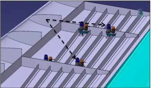
2.1.2 Model Morphing Mechanism
‘Morphing’ is performed via four axial actuators placed inside the wing box (Figure 2.2), and these actuators are fixed two by two to the central ribs. Each actuator is equipped with a piston, attached to the upper skin from the inside, and moves up and down. Each piston is linked to a lead screw that translates the turning motion of a gearbox into a linear motion. Brushless DC motors are used to move the gears inside the actuator mechanism and allow the piston to move linearly.
A linear variable differential transformer (LVDT) sensor is used to monitor the piston motion, and to give an accurate measurement of its displacement. An LVDT “is a type of electrical transformer used for measuring linear displacement” (WIKIPEDIA, 2015b). This position sensor is fixed in parallel with the piston (see Figure-A I-1 in the appendix) and has
1.08 m
21
its tip linked to the piston so that their motion is synchronized. It is therefore possible to change the skin shape using four displacement values applied to their corresponding actuators. Next, we present the system architecture and hardware used for wing parts monitoring.
Figure 2.2 Overview of the morphing mechanism without the upper skin
2.2 Wing control system setup
The upper skin’s ability to be deflected will affect the aerodynamic response of the prototype; however, operating the demonstrator during WTTs and retrieving the required experimental information will only be possible by having a very sophisticated and high-performance control and monitoring system in place. This system is the main key for the success of the experiment as well as of the entire study.
2.2.1 Real time controller NI PXI-e 8135
The core of the wing control system is the embedded real time controller PXI-e 8135 of National Instruments®. The controller runs a real time operating system, and is connected to system hardware peripherals through several input and output modules (Figure 2.3). This
controller is monitored by the Host PC via an Ethernet network using the TCP/IP communication protocol, as it has a static IP address that can be personalized and fixed by the system operator. The windows machine (the Host) will serve for the control program deployment, system state control, and data monitoring in real time.
Figure 2.3 Overview of the wing control system and adopted communications between its components
However, the communication with the target is configured in such a way that losing it will not pose any danger or serious consequences regarding the running of the experiment or its actual state. In fact, all communication tasks, control and data logging will be entirely operated by the PXI, which will run independently of the Host, and its functionalities will be maintained even with no communication with the Host.
23
2.2.2 Fieldbus communications
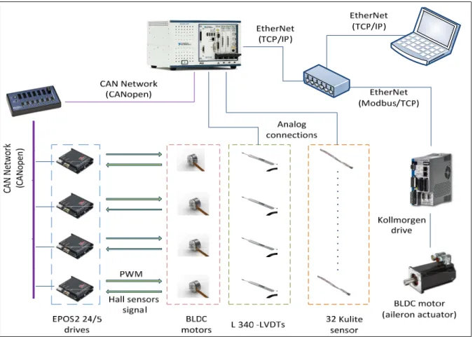
Two types of industrial communication networks were utilized:
• ‘Ethernet’ is used for connecting the real time controller (PXI-e 8135), the Host and the Kollmorgen® Drive (used with the aileron actuator motor). The establishment of the communication between the host (PXI-e) and the Target (operator post) requires a TCP/IP protocol over the Ethernet, while a Modbus/TCP protocol over an Ethernet network is used for the communication between the controller and the Koolmorgen® drive. These three devices are connected via an Ethernet hub, with a distinct IP address for each.
• CAN network provides the connection between the EPOS2 24/5 drives and the controller. However, a 1-Port CANopen interface (NI PXI-8531 module) and a CAN breakout box are needed to set up the network between the Master (Controller) and the Slaves (Drives/CANopen nodes). The CANopen module is able to transmit/receive PDOs and SDOs with a speed of up to 1 Mbit/s.
2.2.3 EPOS2 24/5 drives
The EPOS2 24/5 (Easy to use Positioning System/second generation, type 24/5, 24V-5A) is a modular digital unit used for the positioning of the brushless motors with hall sensors or an encoder; however, it is also suitable for use with brushed DC motors with encoders (Maxon motor control, 2015). Rather than looking at it as a black box, we will need to know (but only to a limited extent) the basics and principles of the working of the drive and its internal architecture functioning.
The drive is built with several communication interfaces and an ‘I/O’ module for digital and analog signals (Figure 2.4). Motor phases and hall sensors are connected on the J2 and J3 modules, respectively. Specially designed to be commanded as a ‘slave’ in a CANopen network, this smart device has a CAN interface (J7/J8). In addition, it can interface with any USB or RS 232 connection (J9 and J6 respectively).
Figure 2.4 Basic internal architecture and interfaces of the EPOS2 24/5 Taken from Maxon motor control (2013b)
The EPOS2 24/5 software makes it possible to tune the embedded controller parameter via the auto-tuning functionality; moreover this is the method we use to tune the drive since it is fast and reliable. However, we cannot guarantee that use this tuning achieves the optimal regulation parameters (Maxon motor control, 2013a).
The drive ensures the electronic commutation of the brushless motor based on feedback from three hall sensors. The regulation architecture is composed of a current loop (inner loop), velocity loop and a position loop.
25
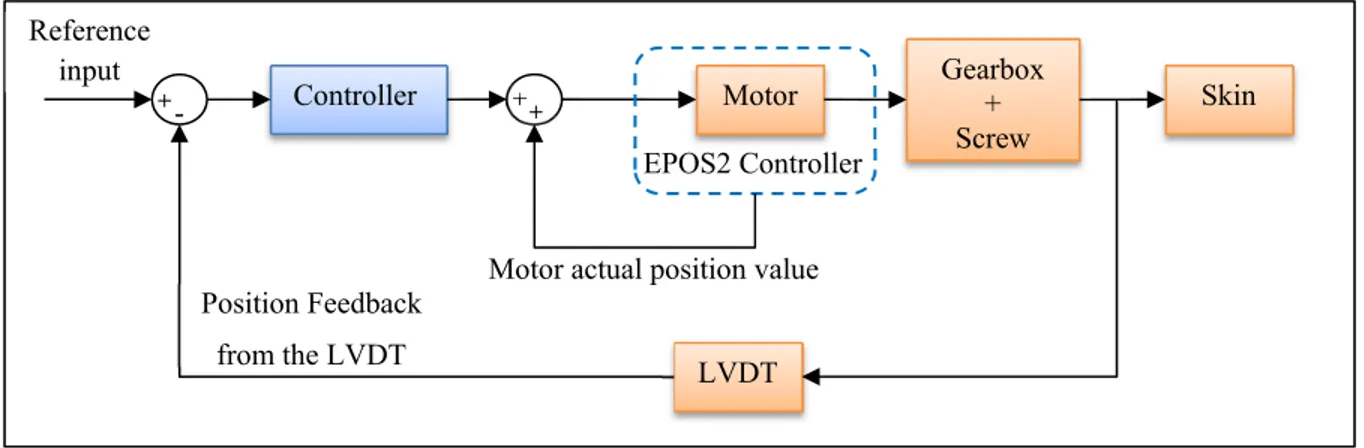
Figure 2.5 EPOS2 24/5 position regulation structure Maxon motor control (2014b)
Figure 2.5 shows the ‘position regulation control’ loops. The inner loop, based on a PI controller, is the ‘current’ regulation loop and does not appear in this representation (positioning plant). The ‘position’ loop is based on a PID controller, with acceleration and velocity feedforward gains.
Another interesting aspect of this smart drive is the varieties of operating modes it offers. In fact, the drive’s behaviour and its functionalities can be selected in accordance with the application’s needs. It is possible to configure the drive in ten (10) different modes, including ‘profile position mode’, ‘homing mode’ and ‘position mode’ (Maxon motor control, 2014b). For our application, the ‘position’ mode is selected as it is both easy to implement and matches our desired functionalities.
2.3 System Software Setup
The main software used for the system control is NI-VeriStand®, which is widely used for real time applications and testing. A project in NI-VeriStand® (Figure 2.6) is composed of at least of three components: a ‘project file’, a ‘system definition file’ and a ‘screen file’ (National Instruments, 2015).
Figure 2.6 NI-VeriStand® project Taken from National Instruments (2015)
• Project file
Defines the high level settings such as the system definition files, the workspace (screen file), configure and run stimulus profiles, configure services, add alarm responses, etc; • System definition file
Contains the configuration settings of the NI-VeriStand® engine as the target rate, real time engine, hardware (DAQ, FPGA…), custom devices, models, system mappings, etc. A brief review of the main parts in the System Explorer Window of the system definition file is presented here:
1) Target: it contains any target a user wishes to add; after adding the target, it is possible to fill in the target specifications. In the system explorer tree, the user can add the hardware list, custom devices, simulation models, calculated channels, etc… 2) Custom devices: are a means to extend and customize the NI-VeriStand® environment. These modules are a sort of LabVIEW® code packaging that can be added to the system definition file.
3) Simulation models: are used to communicate with other system parts that are present in the system definition; real time control operation can be implemented via the model’s inputs and outputs. Once the project is deployed, the inputs and outputs will be updated each time the model is executed (the frequency of running the model is customizable).
27
4) Calculated channels: contain new values calculated on the base of other system channels.
5) System mapping: makes it possible to establish connections between source and destination channels. This mapping is especially useful when the output of a simulation model needs to be linked to the input of a custom device and vice versa. • Workspace:
Defines the configurations and settings for the screen; visualization panels and controls can be added, and all system channels and inputs can be controlled or monitored from this screen. For this project, another labVIEW® based interface was developed for the purpose of wind tunnel testing.
Table 2.1 Software environment description
Software name Description
NI-VeriStand® 2013 Used for real time applications and testing, the main project is deployed on the real time target using NI-VeriStand®
LabVIEW® 2013
Used to develop models for NI VeriStand®.
All the packaged code used for developing custom devices is the LabVIEW® code
Matlab® Simulink 2013 Used for developing control models for NI-VeriStand®
2.4 CANopen communication protocol implementation: Application to the EPOS2 24/5 drives
In this section, Details, on the implementation of the CANopencommunication protocol, are presented. The CAN network and its connection with nodes is presented, and then we explain the programming side of the application with an overview of the internal architecture of the CANopeninterface.
2.4.1 Physical structure of the CANopen network
The CANopen network (Figure 2.7) is composed of a total of five nodes. The real time controller is the Master node; it is connected via the CANopen module ‘NI PXI-8531’ (Section 2.2.2) and its supervising nodes. Four EPSO2 drives are connected in cascade (the network wiring output of one node serves as the network wiring input of the next node). Each of the four drives is considered to be ‘a slave’ node as it provides services under the control of the Network Master.
Figure 2.7 CANopen network structure
The network is terminated on each end by 120Ω resistors. On one end, the resistor is on the NI CANopen breakout box (Section 2.2.2), and the other network end is terminated by a DIP switch on the last node of the network (Figure 2.8). The DIP switch should be set to ‘OFF’ for intermediate nodes.
A unique ‘Node Identification Number’ (node ID) must be assigned to each node. Table 2.2 shows the corresponding node ID of each network device.
CANopen
Master
NI-PXIe
ID-1
CANopen
Slave
EPOS2 24/5
ID-2
Low High GND Shiled Low High GND Shiled
CANopen Slave EPOS2
24/5 ID-5
Low High GND Shiled
....
....
120
29
Figure 2.8 DIP Switch-CAN Bus termination Adapted from Maxon motor control (2014a)
Table 2.2 Nodes identifier mapping
Node Node ID
Real time controller (Master) 1 EPSO2 24/5 drive of actuator ‘1’ (slave) 2 EPSO2 24/5 drive of actuator ‘2’ (slave) 3 EPSO2 24/5 drive of actuator ‘3’ (slave) 4 EPSO2 24/5 drive of actuator ‘4’ (slave) 5
Table 2.3 Node-ID calculation Adapted from Maxon motor control (2014a) Node
ID DIP switch n° 1 2 3 4 5 6 7 Calculation
2 0 1 0 0 0 0 0 21+0=2
The CAN ID may be set by using the software or with the hard DIP switches present on the drive (1...7, see Figure 2.8). An address from 1 to 127 can be assigned by binary code. The CAN ID is determined by the sum of the values of DIP switches set to the ‘ON’ position. An ID value equal to ‘2’ on a DIP switches can be obtained by setting the DIP switch number 2 to ‘ON’ and keeping the others in the ‘OFF’ position (Maxon motor control, 2014a).
DIP Switch ‘OFF’
DIP Switch ‘ON’
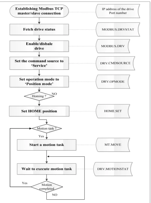
2.4.2 Position mode
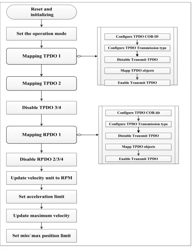
The position mode is simple to implement as it needs a minimal amount of configuration and only few parameters. It only requires a new absolute position value, which can be reached with the maximum acceleration and speed values (Maxon motor control, 2014b).
Figure 2.9 Position Mode Flowchart
Figure 2.9 shows the command sequence for configuring the drive to the ‘Position mode’. The first step consists in setting the operation mode; the second step consists on setting parameters such as the minimum and maximum position limits, maximum velocity and acceleration values. These values make it possible to apply a setting value after the drive is
31
enabled. These commands are based on writing/reading to the drive’s object dictionary through the CANopen interface. Further details are given in the next subsection.
2.4.3 CANopen implementation
Implementation of the CANopen communication is performed via a premade custom device. This custom device was developed for a specific client’s application by engineers at National instruments, it may be provided by NI® upon request.
The custom device reduced our task complexity considerably, as it manages several crucial aspects of the communication. Moreover, it offers an easy to use interface with clearly-defined sections and functionalities.
2.4.3.1 Electronic Data Sheet file
The Electronic Data Sheet (EDS) plays a key role in configuring a CANopen device, as it is a standardized electronic description of the object dictionary. It contains the structure of the object dictionary, and all objects used by the manufacturer of the device. Most importantly, it allows different CANopen software producers access to the device in order to see the object dictionary or to configure it (Schmidt, 2012).
The EDS file can be generated via the EPOS software in EPOS2 drives. It can then be used with the custom device as needed for configuring the EPOS2 drives via NI software. The EDS file path should be specified on the main page of the custom device. The baud rate of the communication is established to 1 Mbit/s. Then, one could start adding device nodes with their IDs. For each node, it is possible then to configure or to add Network Management, Service Data Objects (1.5.2.2) and Process Data Objects (1.5.2.3).
2.4.3.2 CANopen Network Management (NMT)
CANopen network management operates with a Network Master (NMT master) that controls the node’s states on the network (NMT slave), as it follows a Master/Slave structure.
Network management provides several functionalities, including error control services for the initialization of NMT slaves, error control services for node supervision, and communication status and nodes configuration services (Maxon motor control, 2013b).
A node can be switched into three different states: • Pre-Operational;
• Operational; and
• Stopped.
When a device is powered and initialized, it automatically implements a state machine that brings it to the ‘Pre-operational state’. This fact is very important, because it is only in this state that a node can be configured and parameterized via Service Data Object (SDO) sequences. Process Data Objects (PDOs) are not allowed.
Using the NMT protocol, a master can change the machine state of any slave device from the ‘pre-operational’ to the ‘operational’ state and vice versa. Using the custom device, it is possible to implement this feature by choosing the mode in ‘in run state’ before configuration. In the ‘run state’, the nodes (EPOS2 drives in our case) should be in the operational state, so that it is possible to send in/out data via PDOs, and the initial mode
before configuration should be ‘pre-operational’ in order to allow the drive to be configured.
For further details regarding the NMT service and functionalities for each state, please see Appendix II.
2.4.3.3 SDOs Initialization Sequence
Typically, this is the most important phase when implementing the communication system. In this step, the drive will be programmed and prepared to perform as desired during control operations.
33
Using Service Data objects (SDOs), it is possible to access the object dictionary, the core of the smart device. A peer-to-peer communication channel is created between the client and the server allowing reading and writing of the object dictionary entries.
Using the SDOs initialisation sequence is advantageous in our system, as it allows us to adopt the functionalities and drive behaviour to the application’s needs. SDO initialisation makes it possible to choose the working mode (Section 0), to set acceleration/velocity/position limit values and to select which of the process objects are the most determinant. This last point is obviously crucial for our application, as the nature and the amount of the information exchanged on the CANopen network should be determined correctly, otherwise the real time capabilities of the CANopen communication could be significantly deteriorated.
Our application will need to be able to:
• Configure the drive into the position mode, as mentioned in Subsection 0;
• Control the drive status (enable/disable) or to reset the drive in error cases, and to set the position value for the motor;
• Retrieve the information required for the position control loop, such as, for monitoring the motor state:
1) Drive status,
2) Actual position value of the motor, 3) Current actual value average, and 4) Velocity actual value average; and
• Define limits for the acceleration, velocity and position.
Figure 2.10 shows the principle of the drive configuration and programming adopted for the initialization sequence, which is implemented by writing a specific value into the appropriate address of the object dictionary.
For example, the first task during the configuration steps is to ensure that the drive is cleared of any errors, and, is disabled (disable power to the motor and drive function). This specific
operation is performed by writing a specific value to the address ‘6040h’ (addresses are given in hexadecimal in the EPOS2 documentation). For each desired state of the drive (not to be confused with the state machine), there is a value that should be written to the ‘Controlword’, and thus the drive state determines which commands are applicable to the drive (Maxon motor control, 2014c). The drive states and their corresponding control word values are given in Appendices II and III.
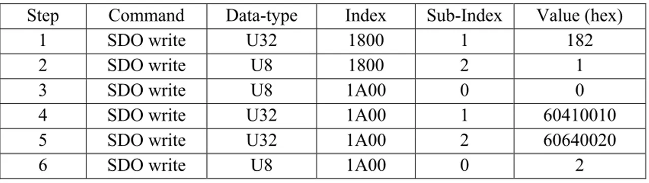
The second step consists in selecting the desired mode in which the drive will operate. This action is realized by writing ‘-1’on the address ‘6060h’ which corresponds to the ‘mode of operation’ parameter in the object dictionary (see appendix VI). However, in the list of SDO sequences given in the ‘Appendix VI’ the value given is indicated as ‘FF’ in hexadecimal and not in decimal format as in the drive documentation. The last four steps in the flowchart are performed in the same manner as for the operation mode selection; each parameter is accessed through the object dictionary with its address, and then the correct value is assigned and so on.
In addition to their use to access the object dictionary, SDOs are also useful to map process data channels. These channels are used to retrieve real time data from each drive, such as the actual motor position and the motor velocity values.
35
2.4.3.4 Mapping TxPDOs and RxPDOs
A rapid way in which is broadcasted data via the network is to use ‘Process Data Objects’ (PDOs), which are high priority messages that can be transferred from one node to another node or to multiple nodes on the same CAN network. Despite being a non-confirmed messaging service (as is the case for SDOs), they are an efficient way to send real time data between nodes (Maxon motor control, 2014b).
In a PDO communication process, are distinguished two PDO services: • Write PDO Service
• Read PDO Service
The concept can be summarized as: ”The producer sends a Transmit PDO (TxPDO) with a specific identifier that corresponds to the identifier of the Receive PDO (RxPDO) of one or more consumers” (Maxon motor control, 2013b).
As an example, let us suppose that we want to send the motor’s current value back to the CANopen master in real time. If we first map the object address which corresponds to this value’s process object into a TxPDO structure then it can be transmitted in real time.
Three types of PDO transmission modes , can be, generally, distinguished (Maxon motor control, 2014b):
• remotely requested; • event triggered; and
• synchronous transmission.
For details about each type of transmission mode, please see the ‘EPOS2 application Notes Collection’. We are only interested in Synchronous transmission as it is the one adopted for our application.