Any correspondence concerning this service should be sent to the repository administrator:
[email protected]
To link to this article:
DOI:10.1016/j.crhy.2011.12.003
URL:
http://dx.doi.org/10.1016/j.crhy.2011.12.003
This is an author-deposited version published in:
http://oatao.univ-toulouse.fr/
Eprints ID: 8729
To cite this version:
Malard, Benoit and Sittner, Petr and Berveiller, Sophie and Patoor, Etienne
Advances in martensitic transformations in Cu-based shape memory alloys
achieved by in situ neutron and synchrotron X-ray diffraction methods. (2012)
Comptes Rendus Physique, vol. 13 (n° 3). pp. 280-292. ISSN 1631-0705
Open Archive Toulouse Archive Ouverte (OATAO)
OATAO is an open access repository that collects the work of Toulouse researchers and
makes it freely available over the web where possible.
Use of large scale facilities for research in metallurgy
Advances in martensitic transformations in Cu-based shape memory
alloys achieved by in situ neutron and synchrotron X-ray diffraction
methods
Apports des grands instruments (neutrons et rayonnement synchrotron) à l’étude de la
transformation martensitique dans des alliages à mémoire de forme à base cuivre
Benoit Malard
a,∗, Petr Sittner
b, Sophie Berveiller
c, Etienne Patoor
caSIMaP, 1260, rue de la piscine, bâtiment Thermo, 38402 Saint Martin d’Hères, France bInstitute of Physics of the ASCR, Na Slovance 2, 182 21 Prague, Czech Republic cArts et Métiers ParisTech, LEM3, 4, rue Augustin-Fresnel, 57078 Metz, France
a b s t r a c t
Keywords:
Stress induced martensitic transformation Cu-based shape memory alloys
Neutron diffraction X-ray synchrotron In situ multiscale analysis
Mots-clés :
Transformation martensitique induite par la contrainte
Alliage à mémoire de forme cuivreux Diffraction de neutrons
Radiation synchrotron Analyses in-situ multiéchelle
This article deals with the application of several X-ray and neutron diffraction methods to investigate the mechanics of a stress induced martensitic transformation in Cu-based shape memory alloy polycrystals. It puts experimental results obtained by two different research groups on different length scales into context with the mechanics of stress induced martensitic transformation in polycrystalline environment.
r é s u m é
Cet article résume une série de travaux où les grands instruments (tels que la diffraction de neutrons et de rayons X du rayonnement synchrotron) ont été appliqués à l’étude de la transformation martensitique induite par la contrainte, dans le cas d’alliages à mémoire de forme cuivreux polycristallins. Il résume les travaux de recherche effectués par différentes équipes dont les résultats ont permis d’identifier les mécanismes physiques mis en jeu à différentes échelles de la microstructure.
1. Introduction
Shape Memory Alloys (SMAs) exhibit reversible hysteretic thermo-mechanical behavior very different from conventional elastic/plastic materials. Unique properties of SMAs, such as the shape memory effect and superelasticity, derive from a martensitic transformation induced by stress and/or temperature changes [1]. Since the martensitic transformation is a diffusionless transition, it can be extremely fast. It is dependent on temperature, stress and history, but not on time, if we disregard the rate dependency stemming from thermo-mechanical coupling due to latent heat exchange with the
*
Corresponding author.E-mail addresses:[email protected](B. Malard),[email protected](P. Sittner),[email protected](S. Berveiller),
[email protected](E. Patoor).
Fig. 1. Comparison of the volume of analysis for an X-ray laboratory, neutron and synchrotron radiations [3].
Table 1
Main characteristics of synchrotron radiation and neutron for stress analysis [4].
Neutrons Synchrotron (high energy)
Penetration in a Cu3Al alloy 20 mm 10 mm
Spatial resolution millimeter (1 mm3) micrometer in the measuring direction millimeter
in the other
Deformation mapping 3D 2D (or 3D)
Full stress tensor yes no or very difficult
Grain sizes problems generally no yes
Counting time 1/2 h–1 h few seconds–minutes
environment [2]. As the martensitic transformation proceeds, the microstructure of SMA changes drastically. If the marten-sitic transformation and/or twinning in martensite are the only deformation processes in constitutive element of SMA and if we can simulate the evolution of microstructure in it and its dependence on stress, temperature and history, we are able to predict any complex hysteretic thermo-mechanical behavior. Detailed simulation of the microstructure evolution during loading is possible only for SMA single crystals; in the case of a polycrystal some sort of micromechanics modeling simulating microstructure evolution and internal stresses in misoriented grains must be adopted.
X-ray and neutron diffraction methods when applied in situ during thermomechanical tests are capable of bringing a corresponding experimental information without interfering with the transformation process, particularly with respect to the detection of changes of phase fractions, texture and stresses in austenite and martensite phases. Since the gauge volume can be varied from micrometres to centimetres, these methods can be applied on multiple length scales. Conventional X-ray laboratory studies are limited to measurements on surface layer with an option to get depth profiles by removing successive layers of material by chemical attack. This technique is not able to measure the components of strain perpendicular (radial strain) to the surface. Neutron and synchrotron high-energy X-rays (typically >60 keV) on the other hand can evaluate strain, texture and phase fractions in the bulk including the strain component perpendicular to the surface. Fig. 1 shows the differences among the three radiations in penetration, diffraction geometry and shape of the gauge volume, where the diffraction signal comes from.
Depending on the size of the gage volume, energetic synchrotron X-rays or neutrons penetrating through millimetre or centimetre sized bulk volumes, respectively, are preferable (see Table 1). While the gauge volume with neutrons tends to be cuboid shaped, it is diamond shaped with synchrotron radiation due to lower diffraction angles.
This work deals application of in situ diffraction methods to the investigation of the stress induced martensitic transfor-mation in pseudoelastic Cu-based SMA polycrystals – i.e. in the area where the results of the two research groups represent majority of results in the literature. They carried out dedicated in situ X-ray and neutron diffraction studies of stress in-duced martensitic transformations in CuAlZnMn [5–10] and CuAlBe [11–13] polycrystalline SMAs on different length scales. Beyond the work of these two groups, only few in situ diffraction studies on stress induced transformations in Cu-based SMAs have been reported in the literature and the most interesting ones were obtained on single crystals. Tidu et al. [14] found that the austenite phase in CuAlBe monocrystal submitted to a fatigue test shows an orthorhombic distortion of the lattice which cannot be explained by residual strain, nor by residual martensite acting like a phase or as a stacking fault.
Since this distortion could have been easily removed by post annealing at 403 K they concluded that diffusional process during ageing or during the mechanical cycling test modify the stable crystal structures. An interesting pioneering diffrac-tion work has been performed by Kannarpady et al. [15] on superelastic cycling of CuAlNi single crystal at 200◦C. They
report very good stability and recoverability of superelastic deformation even after 1000 tensile cycles up to 7% strain. By measuring pole figures under stress on SMARTS diffractometer they found a spread of orientations of the cubic phase at 200◦C around the axis of the wire which periodically disappeared/reappeared during loading/unloading but did not explain
the phenomenon. This article puts the results obtained on Cu-based SMA polycrystals on different length scales into context with the mechanics of stress induced transformation in polycrystalline environment.
2. Neutron diffraction
2.1. Introduction
As already pointed out, thermomechanical behaviours of SMAs are due to the motion of internal interfaces created by the martensitic transformation. This means that the crystal lattice changes due to phase transformations; its orientation (texture) varies due to twinning in martensite phases and its lattice spacing varies due to the elastic deformation caused by external and internal stresses and/or thermal expansion. If only deformation processes derived from the martensitic transformation are involved, these lattice changes are fully reversible in a complete thermomechanical cycle. If other deformation processes such as dislocation slip, creep or cracking are activated, irreversible macroscopic strains are observed and residual stresses and/or stabilized martensite phase remain frozen in the microstructure of the superelastically cycled polycrystal. Information on all of this can be inferred from the in situ diffraction experiments.
In the first part of this article, microstructure evolution and redistribution of load among variously oriented grains of CuAlZnMn polycrystal (load partitioning) deforming superelastically in tension is discussed based on the results achieved by two different neutron diffraction methods – in situ time-of-flight (TOF) measurements on dedicated neutron diffractometer ENGIN-X on pulsed neutron spallation source at ISIS Facility, Chilton, UK [7] and in situ high-resolution evaluation of internal strains on neutron diffractometer SALSA at the nuclear reactor at the Institut Laue Langevin (ILL), Grenoble, France [11–13].
2.2. Cyclic deformation, crystalline anisotropy and load partitioning during superelastic deformation of CuAlZnMn polycrystal
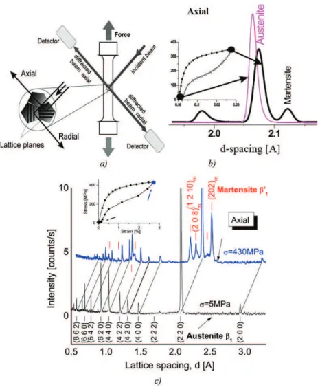
In the TOF in situ neutron diffraction experiment, diffraction patterns are measured in stopovers during thermomechan-ical tests on SMA polycrystals at constant temperature and strain (Fig. 2). The austenite reflections shift to a larger lattice spacing with increasing tensile stress and, when martensitic transformation starts at the knee point of the stress–strain curve, new martensite reflections appear and grow at the expense of shrinking austenite reflections (Figs. 2b, 2c). Individual reflections of the austenite and martensite phases are analyzed (single or multiple peak fits) via their integrated intensities and positions.
Knowing the stress free lattice spacing d0,hkl of the material, the lattice strain
ε
hkl can be calculated from the latticespacing dhkl (peak position evaluated as a centre of the corresponding diffraction peak at the diffraction angleθhkl according
to Eq. (1)) for each measurement point on the stress–strain curve (Fig. 2b).
ε
hkl=
dhkl−
d0,hkl d0,hkl=
1
dhkl d0,hkl= −
cot(θ
hkl)1θ
hkl (1)Since the integral intensity, Ihkl, relates to the volume fractions of the specifically oriented austenite or martensite phases
ξhkl, the martensite volume fraction in{hkl} family of grains for each measurement point can be evaluated using Eq. (2).
ζ
hkl=
µ
1−
Ihkl I0,hkl
(2) The diffraction thus works like a multiprobe that uses crystal lattices of the austenite and martensite phases as built in gauges distributed throughout the bulk volume capable to detect information from in suitably oriented families of equally oriented grains, particularly the lattice strains (from positions of single reflections), phase fractions (from intensities of single reflections), texture in both austenite and martensite phases (from intensities of multiple reflections), defect density and internal stress (from peak widths). The test results are then provided in the form of diagrams describing the evolution of the integral peak parameters with the applied macroscopic stress or strain (Fig. 3).However, in order to understand properly such experimental results, it is essential to keep in mind that the lattice strains and phase fractions evaluated from the peak position and intensity changes in the diffraction experiments are: (1) elastic strains only; (2) crystal orientation specific strains and phase fractions – i.e. determined selectively only from those grains in the polycrystal specimen which are suitably oriented with respect to the scattering vector; (3) phase specific strains – determined selectively only from the volume of the grain existing currently in a given phase – i.e., in austenite or martensite; (4) average strain and phase fraction values over those properly oriented grains within the irradiated volume; (5) the lattice
strain concerns only one component of the elastic strain tensor which is multiaxial in general. Such complex experimental data
can only be rigorously interpreted only through micromechanics modelling of SMA polycrystal transformation providing detailed information about phase fractions, stresses and strains evolving during tensile tests.
Fig. 2. Principle of in situ neutron diffraction measurements on polycrystalline SMAs: a) the specimen (gauge volume∼cm3) is loaded mechanically inside
the neutron diffractometer. The neutron spectra at fixed angular position are recorded by two detectors in two geometric configurations denoted as ‘axial’ and ‘radial’, in which the diffracting lattice planes are oriented either perpendicular or parallel to the tensile load axis, respectively; b) integral intensities and positions of reflections of the austenite and martensite phases are measured at selected [σ,ε,T ] states; c) TOF neutron diffraction spectra of the
CuAlZnMn polycrystal in the axial configuration recorded in the first cycle under tensile stresses of 5 MPa and 430 MPa at room temperature [7]. Fig. 2. Principe de mesure in-situ d’un polycristal par diffraction de neutrons : a) l’éprouvette (volume d’analyse de quelques cm3) est mise en traction dans un diffractomètre de neutrons en temps de vol. Les diffractogrammes de neutrons sont enregistrés par deux détecteurs en configuration géométrique dite ‘axiale’ et ‘radiale’. Dans ces deux configurations les plans diffractants sont respectivement perpendiculaire ou parallèle à la direction de traction ; b) intensi-tés intégrées et positions des pics de diffractions de l’austénite et de la martensite dans un état thermomécanique donné [σ,ε,T ] ; c) diffractogrammes d’un
polycristal CuAlZnMn en configuration ‘axial’ enregistrés lors du premier cycle mécanique à 5 MPa (bas) et à 430 MPa (haut) à température ambiante [7].
Having this in mind, let us briefly discuss the evolution of elastic lattice strains and phase fractions in oriented grains and phases of transforming polycrystalline CuAlZnMn alloy presented in Fig. 3. The points on the two successive tensile macroscopic superelastic curves (Fig. 3a) show the stress–strain states at which the TOF neutron diffraction spectra are recorded. Figs. 3b–3d show the evolution of austenite lattice strains,
ε
hkl, corresponding to various hkl-reflections in theaxial configuration (hkl-plane normal parallel to the loading direction – see Fig. 2a) with the macroscopic stress
σ
G. Notethat the
ε
220 lattice strain does not reach zero upon unloading (Fig. 3b) suggesting that tensile residual strain is left overin the microstructure after the first load cycle. Residual tensile strains frozen in the austenite phase after the first cycle in various families of grains are evaluated. The residual strain is approximately 5×10⁻⁴ in the {220}, {400}, {440} and {422} families of grains. In the {620} grains, however, the residual strain is evaluated to be twice as large. This suggests that even in CuAlZnMn polycrystal, a deformation mechanism different from martensitic transformation such as dislocation slip or micro-cracking has been activated at least in the first superelastic cycle.
Fig. 3 further shows that the normalized integrated intensity Ihkl/I0,hkl of the 220A austenite reflection (Fig. 3e) and
Ihkl of the 200m martensite reflection (Fig. 3g) evolve hysteretically with the macroscopic stress
σ
G and linearly with themacroscopic strain
ε
G (Figs. 3f, 3h). This brings partial information on the microstructure evolution since it relates thevolume fraction of austenite and martensite phases in {220} oriented grains (Eq. (2)) with the macroscopic stress–strain characteristics of superelasticity.
The individual
ε
hkl–σ
G responses (Figs. 3b–3d) reflect the redistribution of stresses among various families of polycrystalFig. 3. In situ neutron diffraction measurements of austenite lattice strain responses in two tensile load cycles on CuAlZnMn polycrystal in the axial configuration: a) macroscopic stress–strain response with denoted measurement points; b) lattice strain of the austenite reflection 220 in 1st and 2nd cycle and lattice strain of austenite reflections; c) 620, 422, and d) 400, 440 – in the 1st cycle only. Evolution of integral intensities of 220 austenite (e, f) and 200mmartensite axial reflections (g, h) with macroscopic stress and strain [7].
Fig. 3. Mesures in-situ par diffraction de neutrons de la déformation de l’austénite (en configuration axiale) dans un alliage CuAlZnMn lors de deux cycles de chargement mécaniques : a) courbe macroscopique contrainte-déformation avec les points de mesures ; b) déformation mesurée sur le pic 220 de l’austénite lors des 1er et 2ème cycles. Et déformation mesurée sur les plans de l’austénite c) 620, 422 d) 400, 440 lors du 1er cycle seulement. Evolution lors du 1er et 2ème cycle sur un alliage polycristallin CuAlZnMn de l’intensité intégrée des plans e) 220 de l’austénite et g) 200 de la martensite en fonction de la contrainte appliquée et f) 220 de l’austénite et g) 200 de la martensite en fonction de la déformation appliquée [7].
well before large-scale transformation resulting in macroscopic yielding takes place (Figs. 3b–3d, 1st cycle, 200–350 MPa stress range). Notice that the onset of the deviation of lattice strain
ε
220 from linearity (Fig. 3b) clearly precedes the fall ofthe intensity I220(Fig. 3e) as well as the appearance and growth of the new 200m martensite peak (Fig. 3g) in the recorded
diffraction pattern (Fig. 2b). The increasing differences between lattice strains in {100} and {110} families of grains in the 200–350 MPa stress range is also worth nothing. This is a direct experimental evidence of the significant redistribution of stresses taking place before the large-scale martensitic transformation can start at the yield point. In other words, it comes out that, before the large-scale homogeneous superelastic deformation can start, local stresses in individual polycrystal grains have to redistribute to get the polycrystal ready for the transformation flow beyond the yielding point on the stress– strain curve.
Looking at Figs. 3e and 3g, the transformation in the second cycle starts at much lower macroscopic stress than in the first cycle. However, taking into account the fact that the lattice strains in the first and second cycle are equal (Fig. 3b), we find out that the local strains in grains of the transforming polycrystals in the first and second cycle are in fact equal, since they are given by the sum of external stress and residual stress left over after the first tensile cycle. This explains why the macroscopic stress in the second cycle is lower.
The redistribution of stress, strain and phase transformation in transforming CuAlZnMn polycrystal has already been extensively discussed based on micromechanics model simulation of the polycrystal transformation elsewhere [5,6,8,9] (the model was first introduced in Ref. [16], later modified [17] and used to simulate the results of in situ neutron diffraction experiments on NiTi polycrystals [18]). The simulations clearly show that martensitic transformation events are triggered in favourably oriented grains in the pre-transformation range, but do not proceed continuously. As a result of these scattered transformation events, however, the stresses and strains in various families of oriented grains drastically redistribute prior to the yield point. One may say that the aggregate of domains in the model adjusts stresses, strains and phase fractions in all its domains to get ready for the large-scale transformation of the polycrystal but once this starts at the yield point, martensitic transformation proceeds more or less with the same speed in most polycrystal grains except for the {111} ones which transform very late [9]. This scenario agrees very well with the results of texture measurements performed on the same CuAlZnMn alloy transforming in tension [10], where no significant transformation induced texture change is observed in the austenite phase (stress induced martensite phase existing under stress is however strongly textured due to the martensite variant selection by the applied stress).
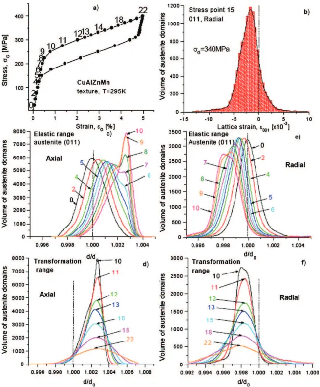
So far, we have been dealing only with peak positions and integrated intensities. However, individual austenite reflections of superelastically transforming CuAlZnMn polycrystal show very interesting reversible profile shape changes, particularly as regards the profile widths FWHM [6–8]. In the literature, the peak profile widths of deformed metals are commonly associated with internal stresses inside polycrystalline grains and related dislocation density. Since the variation of austenite profile shapes of superelastically transforming CuAlZnMn polycrystal takes place already in the elastic range and is nearly reversible during loading–unloading from the second cycle on [6], an alternative explanation needs to be formulated. In order to solve this issue, we have performed micromechanics model simulation of peak profile shape evolution during tensile superelastic cycle as presented in Fig. 4. We assume that the diffraction profile takes approximately a Gaussian shape due to a random distribution of internal stresses assumed to exist in the polycrystal aggregate prior the deformation [8]. As an example, the histogram in Fig. 4b shows the fraction of {011} oriented domains (elements representing polycrystal grains in the model) with particular radial lattice strain in a given binning interval in stress point 15. The envelope of this histogram is the simulated radial diffraction profile in stress point 15. As the tensile stress increases during superelastic stress–strain curve (Figs. 4a, 4c, 4d), the simulated profiles shift from the 0-position to the right (axial) and left (radial) due to anisotropic elastic deformation (points 1–4). When scattered transformation events occur already in the elastic range prior to the macroscopic yielding (points 5–10), profile shape changes drastically, particularly in the case of the axial geometry (Fig. 4c). It can be understood as follows. If the local stress in a single [011] oriented domain approaches the transformation stress level, a transformation event occurs with this domain and the stress decreases stopping further progress of the transformation in this particular domain. As a result, more and more [011] oriented domains reach the stress levels just below the transformation stress and the profile shape width decreases becoming narrowest at the yield point (Fig. 4c – stress point 10). The profile shape change is thus due to the redistribution of load among variously oriented families of domains prior the yield point. When the large-scale transformation proceeds, the load is more and more transferred to the martensite phase leaving the remaining austenite in some domains at low stress but in other domains at high stress since the local stress in almost completely transformed domains steeply increases. This gives rise to significant broadening of simulated diffraction profiles in the transformation stage (Figs. 4e, 4f – stress points 10–22). This peak broadening scenario is completely reversible on unloading, since there is no plastic deformation considered in the model which would provide the space for residual stress generation and irreversible peak broadening. In reality, there have to be other reasons for the reversible peak broadening, e.g. the increasing multiaxiality of stress state in grains [19] and/or reversible austenite lattice rotations reported in Section 3 [11,12]. These could not be considered in the uniaxial model. Since the families of domains representing the axial and radial diffraction geometries are qualitatively different as concerns orientation of domains with respect to the tensile stress, the simulated evolution of axial and radial peak profiles is completely different.
As a conclusion of this part, we would like to point out that the mechanism of the partitioning of stress, strain and phase fraction of the superelastically transforming CuAlZnMn polycrystal as evidenced by the in situ neutron diffraction experiments can be interpreted with the help of micromechanics model simulation of superelasticity. This means that the elastic anisotropy and transformation anisotropy in combination with texture (key material characteristics considered in the
Fig. 4. CuAlZnMn polycrystal in tension at T=295 K. Simulated distributions of the d011-lattice spacing in stress points 0 to 22 during forward loading a),
in axial configuration (c, d), and in radial configuration (e, f). The profiles in (c–f) were obtained as envelope curves of the histograms informing the fraction of {011} oriented domains with particular lattice strain (as the one in (b) for stress point 15 and radial configuration) [8].
Fig. 4. Comportement d’un polycristal de CuAlZnMn lors d’une traction à 295 K a) Courbe contrainte-déformation. Simulation de la distribution de la distance inter-réticulaire des plans {011} en fonction de la contrainte appliquée lors d’une traction entre les points 0 à 22 en configuration axiale (c, d) et radiale (e, f). Les profiles de pics (c–f) sont obtenus avec des courbes enveloppant les histogrammes formant la fraction de domaines orientés selon {011} en fonction des déformations de réseau (comme celui de b) pour la contrainte 340 MPa dans la configuration radiale [8].
model) critically affects the transformability of the polycrystal. In other words, the partitioning of stress, strain and phase fraction discussed above controls the macroscopic superelastic stress–strain response of Cu-based SMA polycrystals.
2.3. Neutron diffraction measurement of stress in austenite during superelastic cycle
In the previous experiment, lattice strains in austenite or martensite phases residing in sets of equally oriented poly-crystal grains were measured. This however does not allow for obtaining direct information on average stress in austenite
Fig. 5. Curves obtained by the sin2ψ method and the method of principal stresses versus the macroscopic applied strain [12,13] during in situ neutron diffraction.
Fig. 5. Courbes obtenues par la méthode des sin2ψet la méthode des contraintes principales en fonction de la déformation appliquée [12,13] par diffraction de neutrons au cours d’un essai in-situ.
and martensite phases. In order to obtain such information, the lattice strain, as measured in the previous paragraph on multiple reflections, is conventionally converted to stress in the austenite phase using diffraction elastic constant. In the case of a two-phase composite, in which austenite transforms to martensite we do not know the diffraction elastic constant for martensite in spite of studies on the structure of the martensite of CuAlBe [20], this approach therefore runs into problems. Alternatively, the stress can be directly evaluated using sin2ψ and principal stress methods conventionally used with X-rays [21]. Malard performed neutron diffraction measurement on polycrystalline CuAlBe cylindrical specimen on the beamline SALSA (angular resolution 0.005◦) of the High Flux Reactor of the ILL [12]. Given the beam size (4 mm2), the width of the
sample (2 mm) and the grain size ∼150 µm, the diffracting volume contains approximately 2500 grains. Such a number of grains is sufficient to consider the diffraction measured stress state to truly represent the stress on the continuum level relevant for continuum mechanics.
Fig. 5 compares the macroscopic tensile stress (dotted line), the stress in the austenite phase in tensile direction, obtained by the sin2ψ method (solid line: points) and by the method of principal stresses (solid line: triangle) as a function of the macroscopic strain. We can see that, in the elastic range (0–240 MPa), the stress state in austenite obtained by both the sin2ψ and the principal stress methods corresponds well to the applied macroscopic stress. When the martensitic transformation proceeds (240–330 MPa) and the sample becomes a two-phase composite with the fraction of austenite increasing and that of martensite decreasing, the stress in the austenite phase stays constant or even decreases if the applied stress continues to increase with increasing strain. This is a direct experimental evidence of the stress transfer from austenite to martensite phase occurring in superelasticity as also revealed by X-rays studies on the same material [19] and considered implicitly in micromechanics SMA modeling discussed in the previous section (Fig. 4f).
The stress state of each individual grain depends strongly on its crystallographic orientation. From all these results, it can be assumed that the behavior of individual grains of the polycrystal is very different and requires a multi-scale analysis. This can be achieved using synchrotron radiation as shown later.
2.4. Residual strain in superelasticity
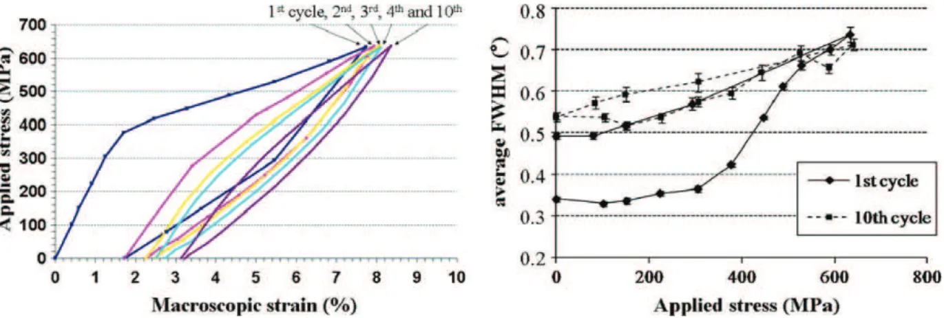
The evolution of superelastic stress–strain response of SMA during cycling has been attracting attention of SMA re-searchers for a long time since it has serious consequences for engineering applications. It was suggested in Section 2.2 that plastic strains occurring in the 1st superelastic cycle on Cu-based SMA leave behind residual stresses which assist the applied stress in inducing martensitic transformation in the 2nd and the following cycles. Malard [12] recently carried out a dedicated in situ neutron diffraction experiment focused on the evaluation of accumulating residual strains during cyclic superelastic deformation (10 cycles at room temperature) of CuAlBe polycrystal. The test was intentionally carried out up to very large strains of the order of 8% (Fig. 6a) in order to activate irreversible plastic deformation due to dislocation slip. It has been found that the significant residual strain (∼1.9%) left after the first cycle (Fig. 6a) corresponds to significant broad-ening of the diffraction profiles (Fig. 6b) but to a relatively small decrease of integrated intensity of austenite reflections after the 1st cycle. See also Figs. 3b–3f.
From the 2nd cycle the residual strain increases only slowly, but the austenite intensity steadily decreases suggesting that irreversible martensite fraction accumulates with further cycling. This suggests that irreversible deformation occurring in the first cycle is indeed largely due to plastic deformation and introduces internal stress into the microstructure which
Fig. 6. Residual strain accumulating during tensile cycling of CuAlBe polycrystal: a) stress–strain curve recorded in 1st, 2nd, 3rd, 4th and the 10th cycles, b) evolution of the average width of different austenite diffraction profiles with applied stress in 1st and 10th cycles.
Fig. 6. Déformation résiduelle s’accumulant au cours de cycles mécaniques dans un polycristal de CuAlBe : a) courbe contrainte–déformation enregistrée lors du 1er, 2ème, 3ème, 4ème et 10ème cycle, b) evolution de la largeur à mi-hauteur moyenne de différents pics de diffraction de l’austénite en fonction de la contrainte appliquée lors du 1er et 10ème cycle superélastique.
modifies the load partitioning in the following cycles. It was found in earlier similar work on CuAlZnMn polycrystal [6] that not just the FWHM (Fig. 9 in [6]) but the whole austenite profiles shape (Fig. 7 in [6]) started to evolve almost reversibly with the applied stress from the 2nd cycle on. As already pointed out in the discussion of Fig. 3 in Section 2.2, reversible peak broadening has nothing to do with a variable density of dislocations, but its nature is again related to the peculiar load partitioning and resultant distribution of d-spacings in phase transforming SMA polycrystals. The model [17,18], however, cannot take into account reversible internal stresses developing most likely within individual grains, which would be an additional source for austenite peak broadening. Synchrotron X-rays studies on the level of single grain reported in the next section reveal details on this.
3. X-ray diffraction of synchrotron radiation
The European Radiation Synchrotron Facility (ESRF) in Grenoble, France, is a 3rd generation source of synchrotron X-rays which provides a unique opportunity to characterize material microstructure in 3D without destroying it. This source generates high energy X-rays in a range of 8 to 150 keV which can penetrate volumes of several centimetres in aluminium and several millimetres in steel [22] for the highest energies. The high flux and low divergence of synchrotron radiation can be exploited by reducing the size of the beam dimensions down to sub-micrometer range for imaging with high spatial resolution [23]. These characteristics of synchrotron sources and detection equipment allow extremely fast measurements. This allows for in situ dynamic studies in polycrystalline grains and subgrains during deformation. The results presented below were achieved by in situ multiscale experimental techniques (3DXRD method and polychromatic micro-diffraction) applied to the problem of mechanics of stress induced martensitic transformation in Cu-based SMAs.
3.1. Experimental methods 3.1.1. The 3DXRD technique
The concept of the 3DXRD microscope is based on the measurement of local crystallographic orientations to create maps of the microstructure. The 3DXRD method combines the high penetration, high intensity and high spatial resolution provided by X-rays synchrotron radiation. The incident beam is monochromatic and the spatial resolution is about 5 µm. The basic concepts of this technique are detailed in [24,25]. The value of this 3DXRD method is the three-dimensional localization of the crystallites and fast evaluation of lattice orientation in the volume of a thick polycrystal. In the work described below, a CuAlBe polycrystal was used with a mean grain size of about 1 mm. Experiments were performed on beamline ID11 at ESRF with a beam size of 200 µm×200 µm. At each measurement position, very few grains are diffracting simultaneously.
3.1.2. The “Micro-Laue” technique or polychromatic micro-diffraction
Diffraction of synchrotron radiation with a polychromatic micro-beam can be used to perform local measurements on the surface of a single grain within the polycrystal. From the diffraction pattern, to the crystallographic orientation and the deviatoric part of the strain can be determined without moving the specimen. Due to the small size of the beam, it is possible to map microstructure and strain heterogeneities within a single grain. The basic principles of the micro-Laue technique are introduced in detail in [26,27]. This technique is used to follow the microstructure evolution within a single grain in a CuAlBe polycrystal during in situ tensile testing. The selected grain was about one millimeter wide. The measurements were made using polychromatic beam (from 5 to 25 keV) on the line BM32 at the ESRF. The micro-beam of 2 µm diameter penetrates to a depth of 70 µm at 25 keV.
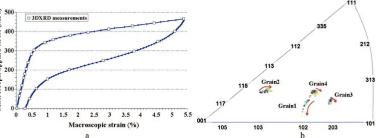
Fig. 7. a) Macroscopic tensile stress–strain curve of the CuAlBe specimen and the measurement points, b) representation of the orientation evolution of the four austenite grains in a stereographic representation in tensile direction between 0 MPa to 465 MPa (0% to 5.4% strain) [11,12].
Fig. 7. a) Courbe contrainte déformation de l’éprouvette en CuAlBe avec les points de mesures, b) représentation de l’évolution d’orientation de 4 grains d’austénite dans une représentation stéréographique lors d’un essai de traction de 0 MPa à 465 MPa [11,12].
Fig. 8. Zoom on grain #2 of Fig. 7b. The black arrows represent the grain orientation evolution from 0 MPa to 465 MPa. The dotted lines track the orientation changes of the austenitic sub-domains with increasing applied stress [11,12].
Fig. 8. Zoom du grain #2 de la Fig. 7b. Les flèches noires pleines représentent l’évolution de l’orientation du grain de 0 MPa à 465 MPa. Les formes en pointillées relient les orientations des sous-domaines austénitiques à une contrainte appliquée donnée.
3.2. Evolution of individual grain rotation and intragranular heterogeneities
Berveiller et al. [11] followed changes of the orientation of four austenite grains during a superelastic cycle (Fig. 7a) within the CuAlBe SMA specimen. Their Schmid factor for transformation varies between 0.3 and 0.49 and during loading, the four grains rotate in directions and with a magnitude depending on their initial crystallographic orientation (Fig. 7b); the maximum rotation angle is 2.5◦in that study. The pseudo “Schmid factors” associated to transformation are almost not
affected by this rotation: they do not increase significantly nor decrease.
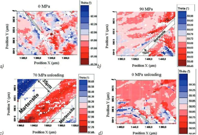
When looking at the presented evolution of the orientation (Fig. 8), two domains are clearly visible. In the elastic de-formation domain, the grains orientation is quite homogeneous, but as the transde-formation proceeds, this average rotation is accompanied by the formation of misoriented sub-domains within the grain. The origin of these sub-domains is identified by orientation maps obtained by the Laue-microdiffraction (Fig. 9b). The rotated regions appear on each side of the marten-site plate. This austenite orientation change probably accommodates strain incompatibilities created at the interface as the grain transforms into martensite. The misorientation between sub-domains (i.e. different orientations within the grain) as
Fig. 9. Map of the local lattice orientation (θ angle) of the austenite as a function of loading stress: a) initial map at 0 MPa; b) at 90 MPa during loading; c) 70 MPa during unloading and d) after complete unloading 0 MPa. The small white ellipse indicates a retained martensite variant. The white area in b) corresponds to a stress-induced martensite plate [11,12].
Fig. 9. Cartographie d’orientation locale de l’angle d’Eulerθdu réseau cristallin de l’austénite en fonction de la contrainte appliquée : a) cartographie initiale à 0 MPa ; b) à 90 MPa en charge ; c) à 70 MPa durant la décharge ; d) après le déchargement complet à 0 MPa. La petite ellipse dans a) est un variant de martensite résiduel. Les zones blanches dans b) correspondent à de la martensite induite par la contrainte [11,12].
well as their number increases during loading and decreases during unloading. Notice that in both experiments, the same maximum rotation angle is observed, which underlines the consistence of the analysis. After unloading, the austenite rotated back towards its initial average orientation with a residual rotation of about 0.4◦ [11]. At the same time, the sub-domains
of austenite rotate and collapse again as the martensite variants disappear; when unloading is complete, only one domain is observed as at the initial state. These reversible austenite rotations explain very well the curious reversible pole figure changes observed by Kannerpady et al. on superelastically cycles CuAlNi single crystals [15].
These results also confirm that the reversible diffraction peak broadening measured in neutron diffraction experiment [6, 12] has indeed multiple origins as suggested in Section 2. In addition to the scatter of stresses in family of equally oriented grains, there are significant stress heterogeneities in austenite phase within individual grains due to the formation and the rotations of the austenitic sub-domains. Therefore the Schmid factor calculation is not sufficient to describe properly the stress acting on martensitic transformation. These intragranular stress heterogeneities (orientation and stress) should be accounted for. In fact, it was observed that a grain with a lower Schmid factor transforms before more suitably oriented grains [19]. These results contradict with what is generally assumed in micromechanics modelling of SMAs [28,29].
In conclusion, the synchrotron X-ray studies show that the martensitic transformation induces strong stress hetero-geneities not only between grains but also within the grains. A complex stress state far from the imposed uniaxial tension exists in embedded grain of transforming polycrystal. However, if the internal stress is taken into account to calculate the critical shear stress, the same value is found for all the grains. This suggests that the SMA models assuming stresses in grains based on the applied stress only might be very far from reality.
Finally, to put the present work into a broader perspective, it should be noted that much more in situ neutron diffraction work reported in the literature in the last decade in fact focused the commercially more successful NiTi alloy [17,30– 37]. Although the above discussed results are qualitatively applicable for NiTi based phase transforming materials and the approach including the modelling was in fact applied mainly to NiTi alloys [16–18], it is worth of keeping in mind the key differences – NiTi alloys are less anisotropic, prone to plastic deformation, frequently exhibit R-phase transformation which
complicates analysis of the peak shifts, grains size in heavily drawn wires can be as small as 20–50 nm compared to mm sized grains of Cu-based alloys and, finally, NiTi is much poorer neutron scattered than Cu-based alloys. It is mainly due to the first two points that the Cu-based alloys are better model material for investigation of the mechanics of stress induced martensitic transformation. Combination of extreme elastic and transformation anisotropies [16] with high resistance to plasticity and large grain size makes alloys as CuAlNi or CuAlBe prone to inter-crystalline fracture in polycrystal form. Although this is a serious problem for engineering applications, it is beneficial for diffraction studies since the phenomena of concern are more pronounced. In situ diffraction work on NiTi-based alloys [17,30–37] is, on the other hand, more relevant from engineering applications point of view and, particularly due to the last two points, the energetic synchrotron X-rays [35–37] are even more convenient for in situ studies on small sized NiTi samples.
4. Conclusions
X-ray and neutron diffraction methods were applied to the investigation of the mechanics of stress induced martensitic transformation in superelastic tensile tests of Cu-based shape memory alloy polycrystals on two different length scales – macroscopic (gauge volume of a few mm3) and individual grain (gauge volume of few µm3) of the transforming polycrystal.
The in situ TOF neutron diffraction experiments have clearly shown that as the polycrystal deforms in the tensile test, the applied stress, strain and phase fractions continuously redistribute among the polycrystal grains. Based on the results of micromechanics modelling, it is claimed that the combined effects of elastic anisotropy, transformation anisotropy, polycrys-talline texture and applied stress state (tension or compression in the case of uniaxial loadings) are the key factors affecting the stress, strain and phase fraction partitioning. This partitioning thus controls the transformability and the shape of the stress–strain curve of the polycrystal. The partitioning can be significantly modified by texture and grain size control.
Experiments performed during cyclic tensile tests on Cu-based polycrystals (irreversible lattice strains and profile shape changes) have proven that residual stresses are introduced mainly in the first tensile cycle. The irreversible deformation in the first cycle due to the plastic deformation introduces internal stresses into the microstructure which in turn modify the load partitioning (and consequently the shape of stress–strain curve) in the second and following tensile cycles. Reversible austenite peak broadening with applied stress is observed in cyclic tensile experiments. This is again related to the reversible load partitioning during tensile cycling.
High resolution strain measurements on diffractometer SALSA at a neutron reactor source provided direct experimental evidence for stress transfer from the austenite to the martensite phase during superelastic deformation of CuAlBe polycrystal. The in situ 3DXRD synchrotron experiments show that the martensitic transformation in a single embedded grain is accompanied by a significant reversible austenite lattice rotation and splitting into sub-domains of different orientations. Laue micro-diffraction was used to map the austenite lattice orientation changes in presence of stress induced martensite plates. This analysis confirmed that once martensite plate forms in the grain, the austenite lattice on both sides of the plate rotates in different directions splitting the grain into subdomains of different orientations. It is argued that this lattice rotation is due to stress inhomogeneity within a single grain undergoing martensitic transformation. Upon unloading the original austenite lattice is fully restored. This reversible intragranular stress appearing under loading and disappearing upon unloading is thought to be co-responsible for the reversible austenite peak broadening observed in TOF neutron diffraction experiments during cyclic deformation.
References
[1] K. Otsuka, C.M. Wayman, in: K. Otsuka, C.M. Wayman (Eds.), Shape Memory Alloys, Cambridge University Press, 1998, p. 27.
[2] L. Heller, et al., in: G.B. Olson, D.S. Lieberman, A. Saxena (Eds.), Proceedings Icomat 2008, Santa Fe USA, The Minerals, Metals & Materials Society, 2009, pp. 445–452.
[3] A.D. Evans, Residual stress characterisation of peened aerospace materials, PhD thesis University of Manchester, 2005. [4] P.J. Withers, Depth capabilities of neutron and synchrotron diffraction strain, J. Appl. Cryst. 37 (2004) 607–612.
[5] P. Šittner, et al., in: Proc. of IUTAM 2001, in: Solid Mechanics and its Applications, vol. 101, Kluwer Academic Publishers, 2001, p. 179.
[6] D. Neov, et al., In situ high resolution neutron diffraction study of stress induced martensitic transformation in CuAlZnMn shape memory alloy, in: Proc. of the 5th European Conference on Residual Stresses, Mat. Sci. For. 347–349 (2000) 334–339.
[7] P. Šittner, et al., Stress induced martensitic transformation in CuAlZnMn polycrystal investigated by two in situ neutron diffraction techniques, Mat. Sci. Eng. A 324 (1–2) (2002) 225–234.
[8] P. Šittner, et al., Load partition in shape memory alloy polycrystals, in: M. Tokuda, B. Xu (Eds.), Proc. of Immm, Mie University Press, Tsu, Japan, 2001, pp. 35–46.
[9] P. Šittner, et al. Characterization of stress induced martensitic transformation in shape memory alloys by in situ neutron diffraction techniques, in: J. Redmond, J. Main (Eds.), Proc. of Adaptive Structures and Material Systems, AD-vol. 60, Orlando, FL, 2000, pp. 25–35.
[10] D. Neov, et al., in: XVIII Conference on Applied Crystallography (CAC), Poland, 2000.
[11] S. Berveiller, et al., In situ synchrotron analysis of lattice rotations in individual grains during stress-induced martensitic transformations in a polycrys-talline CuAlBe shape memory alloy, Acta Materialia 59 (2011) 3636–3645.
[12] B. Malard, Caractérisation multiéchelle par diffraction de neutrons et rayonnement synchrotron de la transformation martensitique sous contrainte dans un alliage à mémoire de forme CuAlBe, Thèse de doctorat de l’ENSAM (CER Metz), 2008,http://pastel.archives-ouvertes.fr/pastel-00004479/en/. [13] B. Malard, et al., Stress determination during the mechanically-induced martensite phase transformation in the superelastic alloy CuAlBe by neutron
diffraction, Mat. Sci. Forum 524 (2006) 905–910.
[14] A. Tidu, et al., Orthorhombic lattice deformation of CuAlBe shape-memory single crystals under cyclic strain, J. Appl. Cryst. 34 (2001) 722–729. [15] G.K. Kannarpady, et al., Phase quantification during pseudoelastic cycling of Cu–13.1Al–4.0Ni (wt.%) single-crystal shape memory alloys using neutron
[16] P. Šittner, V. Novák, Anisotropy of martensitic transformations in modeling of shape memory alloy polycrystals, Int. J. Plast. 16 (2000) 1243–1268. [17] V. Novák, P. Šittner, Micromechanics modelling of NiTi polycrystalline aggregates transforming under tension and compression stress, Mat. Sci. Eng.
A 378 (1–2) (2004) 490–498.
[18] P. Šittner, et al., In situ neutron diffraction studies of martensitic transformations in NiTi polycrystals under tension and compression stress, Mat. Sci. Eng. A 378 (1–2) (2004) 97–104.
[19] B. Kaouache, Analyse multiéchelles de la transformation martensitique induite par contrainte dans les AMFs. Corrélation contraintes-microstructure, Thèse de doctorat de l’ENSAM (CER, Metz), 2006,http://pastel.archives-ouvertes.fr/docs/00/50/03/95/PDF/These-B-KAOUACHE.pdf.
[20] F. Moreau, Etude par diffraction des rayons X des effets du cyclage pseudoélastique de AMF CuAlBe, Thèse de doctorat de l’Université de Metz, 1998. [21] I. Noyan, J. Cohen, Residual Stress Measurement by Diffraction and Interpretation, Springer Verlag, New York, 1987.
[22] C.A. Volkert, et al. in: C. Gundlach, et al. (Eds.), Proc. 25th Risø Int. Symp. Mater. Sci., Risø National Laboratory, Denmark, 2004, pp. 171. [23] J.R. Schneider, et al., High energy synchrotron radiation. A new probe for condensed matter research, J. Phys. IV France 4 (1994) 415–421. [24] H.F. Poulsen, Three-Dimensional X-Ray Diffraction Microscopy: Mapping Polycrystals and their Dynamics, Springer Tracts in Modern Physics, 2005. [25] E.M. Lauridsen, et al., Tracking: A method for structural characterization of grains in powders or polycrystals, J. Appl. Cryst. 34 (2001) 744–750. [26] A.A. MacDowell, et al., Nucl. Instrum. Meth. Phys. Res. A 467 (2001) 936–943.
[27] N. Tamura, et al., High spatial resolution stress measurements using synchrotron based scanning X-ray microdiffraction with white or monochromatic beam, Mat. Sci. Eng. A 399 (1–2) (2005) 92–98.
[28] Q.P. Sun, et al., Micromechanics constitutive description of thermoelastic martensitic transformations, Adv. Appl. Mech. 31 (1994) 249–298. [29] M. Tokuda, et al., Thermomechanical behavior of shape memory alloy under complex loading conditions, Int. J. Plast. 15 (1999) 223–239.
[30] R. Vaidyanathan, et al., Phase fraction, texture and strain evolution in superelastic NiTi and NiTi±TiC composite investigated by neutron diffraction, Acta Materialia 47 (12) (1999) 3353–3366.
[31] S. Qiu, et al., On elastic moduli and elastic anisotropy in polycrystalline martensitic NiTi, Acta Materialia 59 (2011) 5055–5066.
[32] M.L. Young, et al., Phase volume fractions and strain measurements in an ultrafine-grained NiTi shape-memory alloy during tensile loading, Acta Materialia 58 (2010) 2344–2354.
[33] A. Stebner, et al., Neutron diffraction studies and multivariant simulations of shape memory alloys: Empirical texture development–mechanical re-sponse relations of martensitic nickel–titanium, Acta Materialia 59 (2011) 2841–2849.
[34] B. Ye, et al., Texture development and strain hysteresis in a NiTi shape-memory alloy during thermal cycling under load, Acta Materialia 57 (2009) 2403–2417.
[35] S.L. Raghunathan, et al., In situ observation of individual variant transformations in polycrystalline NiTi, Scripta Materialia 59 (2008) 1059–1062. [36] M. Hasan, et al., X-ray studies of stress-induced phase transformations of superelastic NiTi shape memory alloys under uniaxial load, Mat. Sci. Eng.
A 481–482 (2008) 414–419.
[37] B. Malard, et al., In-situ investigation of the fast microstructure evolution during electropulse treatment of cold drawn NiTi wires, Acta Materialia 59 (2011) 1542–1556.
![Fig. 1. Comparison of the volume of analysis for an X-ray laboratory, neutron and synchrotron radiations [3].](https://thumb-eu.123doks.com/thumbv2/123doknet/3603536.105717/3.892.194.691.110.438/fig-comparison-volume-analysis-laboratory-neutron-synchrotron-radiations.webp)

![Fig. 5. Curves obtained by the sin 2 ψ method and the method of principal stresses versus the macroscopic applied strain [12,13] during in situ neutron diffraction.](https://thumb-eu.123doks.com/thumbv2/123doknet/3603536.105717/9.892.187.699.107.407/curves-obtained-principal-stresses-macroscopic-applied-neutron-diffraction.webp)