HAL Id: pastel-00565881
https://pastel.archives-ouvertes.fr/pastel-00565881
Submitted on 14 Feb 2011HAL is a multi-disciplinary open access archive for the deposit and dissemination of sci-entific research documents, whether they are pub-lished or not. The documents may come from teaching and research institutions in France or
L’archive ouverte pluridisciplinaire HAL, est destinée au dépôt et à la diffusion de documents scientifiques de niveau recherche, publiés ou non, émanant des établissements d’enseignement et de recherche français ou étrangers, des laboratoires
Implementation and Countermeasures.
Nidhal Selmane
To cite this version:
Nidhal Selmane. Global and local Fault attacks on AES cryptoprocessor : Implementation and Countermeasures.. Cryptography and Security [cs.CR]. Télécom ParisTech, 2010. English. �pastel-00565881�
Télécommunications et Électronique de Paris
Thèse
présentée pour obtenir le grade de docteur
de Télécom Paris Tech
Spécialité : Électronique et communication
Nidhal SELMANE
Attaques en fautes globales et locales sur
les cryptoprocesseurs AES : mise en
œuvre et contremesures
Soutenance prévue le 13 Décembre 2010 devant le jury composé de
David NACCACHE Rapporteurs
Regis LEVEUGLE
Guido BERTONI Examinateurs
Jacques FOURNIER Habib MEHREZ Gilles PIRET
Jean-Luc DANGER Directeurs de thèse
I would like to acknowledge all the people who supported me during my research.
First and formost, i would like to thank my thesis director Jean-luc Danger for his valuable guidance and supports, his understanding and encourag-ing have provided a good basis for the present thesis. I would like also to express my deep and sincere gratitude to my supervisor Sylvain Guilley, his wide knowledge and his logical way of thinking have been of great value for me.
Furthermore, I wish to express my warm and sincere thanks to the mem-bers of my reading committee, David Naccache, Regis Leveugle, Jacques Fournier and Guido Bertoni how have accepted to evaluate my work and for their detailed and constructive comments.
Moreover, During this work I have collaborated with many colleagues for whom I have great regard, and I wish to extend my warmest thanks to all those who have helped me with my work in COMELEC. Especially, i would like to mention Sami Mekki, Youssef Suissi, Shivam Basin, Hossem Magrebi, Zouha Chrif, Taoufik Chouta, Maxim Nassar, Sebastien Thomas, Oliver Meynard, Aziz ElAbid, Laurent Sauvage, Florent Falment, Som-pasong Somsavaddy, Chantale Cadiat, Daniel Childz, Zouina Sahnoune, Karim Ben Kalaia, Guillome Duc, Tarik Grabaa, Lirda Naviner and Philippe Matehrat.
Finally, i would like to thank my family for their support through my ed-ucation and studies. Without their encouragement and understanding it would have been impossible for me to finish this work.
List of Figures vii
List of Tables xi
1 Résumé 1
2 Physical Attack On Cryptographic Implementation 21
2.1 Cryptography . . . 21
2.1.1 Symmetric Ciphers . . . 22
2.1.2 Asymmetric Cryptography . . . 30
2.2 Smartcard Architecture . . . 33
2.3 Side Channel Attack . . . 35
2.3.1 Timing Attack . . . 35 2.3.2 Power Analysis . . . 36 2.3.3 Electromagnetic Analysis . . . 39 2.4 Fault Attacks . . . 40 2.4.1 Power Spikes . . . 40 2.4.2 Clock Glitches . . . 40 2.4.3 Optical Attack . . . 41
2.4.4 Electromagnetic Perturbations Attack . . . 41
2.4.5 Definition of Fault Model . . . 42
2.4.6 Fault Attack on AES . . . 43
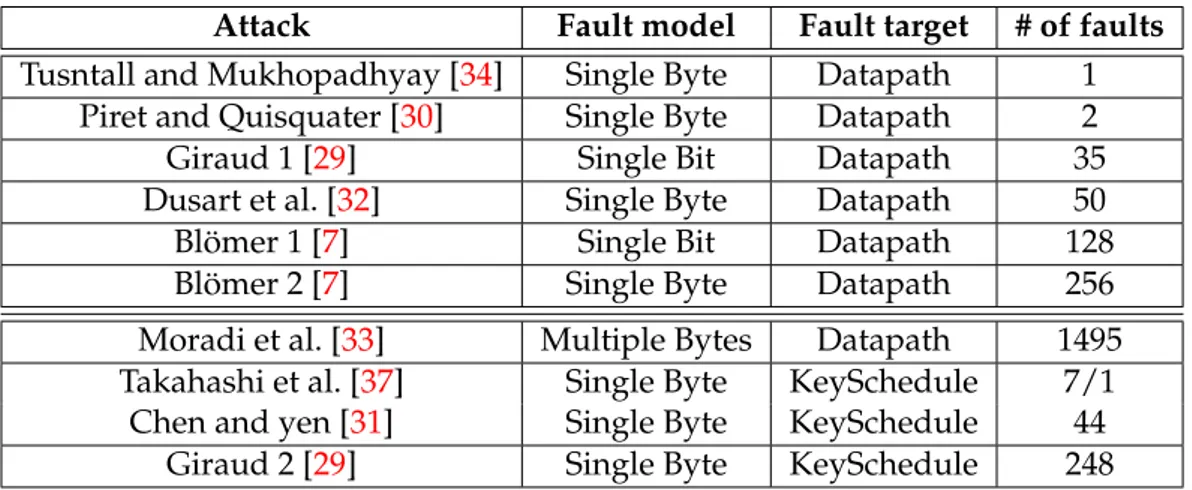
2.4.7 Summary of DFA on AES . . . 50
2.5 Conclusion . . . 51
3 Practical Attacks on AES 53 3.1 Global Attack: Setup time violation attack . . . 53
3.1.2 Acquisition Platform . . . 55
3.1.3 Fault Analysis . . . 56
3.1.4 Attack on ASIC . . . 58
3.1.5 Attack on FPGA . . . 61
3.2 Local Attack: Optical Fault Injection . . . 74
3.2.1 Decapsulation . . . 74
3.2.2 Practical Setup . . . 75
3.2.3 Experimental Results . . . 77
3.3 Conclusion . . . 78
4 Fault Attack Countermeasures 81 4.1 Fault Detection . . . 82
4.1.1 Parity . . . 82
4.1.2 Concurrent Error Detection . . . 83
4.1.3 Cyclic Redundancy Check . . . 83
4.1.4 Non Linear Robust Code . . . 84
4.1.5 Double-Data-Rate as countermeasure . . . 86
4.1.6 Low cost countermeasure against setup time violation attacks . . 86
4.2 Fault Resilience . . . 88
4.2.1 Comparison between Detection and Resilience . . . 88
4.2.2 Further Merits of the Fault Injection Resilience ”FIR” . . . 90
4.2.3 Related Works . . . 90
4.2.4 Some Practical Implementations of FIR . . . 91
4.2.5 Dual-Rail with Precharge Logic as a Global Countermeasure against Implementation-Level Attacks . . . 96
4.2.6 Cost Estimation of FIR versus Traditional Approaches . . . 104
4.2.7 Associating Three Protections to Reduce the Probability of a Suc-cessful FIA . . . 107
4.2.8 Applicability of Resilience with Certification Procedures . . . 108
4.3 Case study on WDLL . . . 109
4.3.1 Wave Dynamic Differential Logic . . . 109
4.3.2 Design Flow for WDDL Implementation . . . 111
4.3.3 Experimental Results . . . 113
4.3.4 Theoretical Fault Analysis on AES in WDDL . . . 115
4.3.6 Analysis of the DFA Protection for DPL w/o EPE . . . 122
4.4 Conclusion . . . 126
5 Conclusion 127
1.1 standard de chiffrement AES . . . 3
1.2 Injection de l’erreur dans AES . . . 5
1.3 Erreur dans le tour 9 . . . 5
1.4 Erreur dans le tour 8 . . . 6
1.5 Violation de temps de setup . . . 7
1.6 Plate-forme d’injection de fautes . . . 8
1.7 Occurrence des fautes — (tension). . . 9
1.8 Occurrence des fautes (fréquence). . . 9
1.9 Architecture du cryptoprocesseur AES . . . 11
1.10 Occurrence des fautes simple dans Altera Stratix. . . 12
1.11 Occurrence des fautes simple dans Xilinx Virtex5. . . 12
1.12 Plate-forme d’injection optique . . . 13
1.13 Cartographie des fautes . . . 13
1.14 Code robuste non-linéaire . . . 15
1.15 protocole DPL . . . 16
1.16 occurrence des fautes dans une version wddl d’AES . . . 17
2.1 Data Encryption Standard . . . 24
2.2 AES encryption . . . 26
2.3 SubBytes transformation [1]. . . 27
2.4 ShiftRow transformation [1]. . . 27
2.5 MixColumn transformation [1]. . . 28
2.6 AddRoundKey operation . . . 29
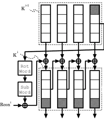
2.7 AES Key Schedule . . . 29
2.8 Smartcard internal architecture . . . 34
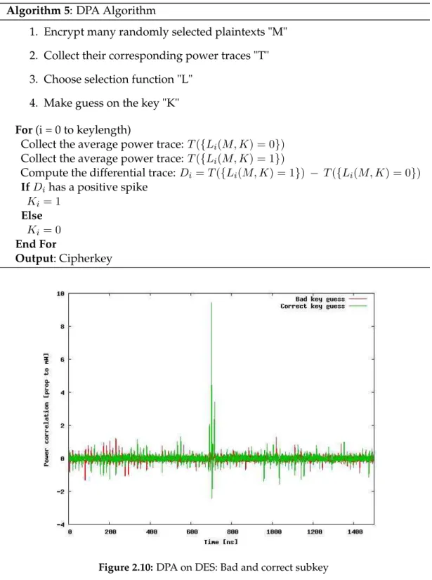
2.10 DPA on DES: Bad and correct subkey . . . 38
2.11 EMA on DES: Bad and correct subkey . . . 39
2.12 Fault effect on round 9 of AES. . . 48
2.13 Fault effect on round 8 of AES . . . 49
3.1 Setup violation. . . 55
3.2 Experimental faults injection platform . . . 56
3.3 AES faults analysis. . . 57
3.4 Occurrence of Fault — (power). . . 58
3.5 Occurrence of fault (over-clocking). . . 58
3.6 Coverage of exploitable faults. . . 59
3.7 Temporal localization of single faults. . . 61
3.8 Spatial localization of single faults.The SubBytes box si,jhas index 4 × i + j in the histogram. . . 61
3.9 Simple AES. . . 62
3.10 AES architecture. . . 63
3.11 Composite Field implementation of SubBytes . . . 63
3.12 Occurrence of faults: sbox in GF (24).( ALTERA) . . . . 64
3.13 Occurrence of faults: sbox in LUT. (ALTERA) . . . 65
3.14 Occurrence of faults: sbox in RAM.(ALTERA) . . . 65
3.15 Coverage of single faults, and detail of exploitable faults in GF (24). . . . 66
3.16 Coverage of single faults, and detail of exploitable faults in LUT. . . 66
3.17 Coverage of single faults, and detail of exploitable faults in RAM. . . 68
3.18 Hamming weight of exploitable faults in GF (24). . . . 68
3.19 Exploitable errors ”Round 8 and 9”. . . 69
3.20 AES architecture with critical path strictly confined in the datapath. . . . 71
3.21 Temporal localization of single fault on Altera GF(24). . . . 71
3.22 Occurrence of single Faults (Altera Stratix) . . . 73
3.23 Occurrence of single faults (Xilinx Virtex5) . . . 73
3.24 Optical fault injection platform . . . 76
3.25 Temporal localization with random hit . . . 77
3.26 Cartography of faults . . . 78
4.1 Parity based countermeasure . . . 83
4.2 Concurrent error detection . . . 84
4.4 Double-Data-Rate as countermeasure . . . 86
4.5 Counter-measure based on the insertion of a monitoring logic with a propagation time larger than the critical path of the rest of the circuit. . . 86
4.6 Chain Voltage/lcell. . . 87
4.7 Suicide in case of fault detection (top), opposed to survival in case of fault resilience (bottom) protection schemes. . . 90
4.8 Probabilistic encryption and deterministic decryption . . . 93
4.9 Two kinds of faults for 3-valued logic and for DPL, . . . 95
4.10 Susceptible organs of a smartcard in two representative sensitive oper-ations (EXTERNAL AUTHENTICATE and INTERNAL AUTHENTICATE). Typically, the cryptography will be triple-DES or AES. . . 97
4.11 DPL protocol. . . 98
4.12 Two DPL w/ EE drawbacks to fight DFAs, illustrated on the example of a WDDL AND gate. In this figure and in the subsequent ones, the asterisk character (*) symbolizes the faults. . . 101
4.13 Difference of detection and resilience working factors, represented on an example netlist. . . 103
4.14 Memorization element in TMR. . . 106
4.15 Memorization element in DPL. . . 107
4.16 Multiple faults, where the false valid is not completely hidden by the ’X’wave. . . 108
4.17 Timing diagram for a WDDL AND gate. . . 110
4.18 WDDL building block. . . 111
4.19 WDDL design flow. . . 112
4.20 occurrence of faults in wddl version . . . 113
4.21 Temporal and Spatial localization of single faults for the Wddl imple-mentation . . . 114
4.22 WDDL implementation of the XOR gate. . . 117
4.23 Dual-to-single rail circuitry usable in the case of a NULL0 spacer. . . 119
4.24 WDDL w/o AND gate . . . 122
4.25 Probability that m faults injected on n wires be innocuous due to the protection conveyed by two different countermeasures: either a detec-tion by an informational redundancy scheme or an annihilation of the faulted databy one or several VALID→∗ NULL token transformations. . . 125
1.1 Localisation temporelle et spatial de fautes simples dans Altera Stratix . 10
1.2 Altera Vs Xilinx . . . 12
2.1 Summary of Differential Fault Attack . . . 51
3.1 Temporal and Spatial localization of single faults on Altera Stratix board 67 3.2 Temporal and Spatial localization of single faults on Xilinx Virtex 5 board . . . 72
3.3 Characterization and attack results for Altera and Xilinx with the three Sbox architectures. . . 73
4.1 Nonlinear Robust code implementation. . . 85
4.2 Classical fault detection characteristics. . . 88
4.3 Performance overhead of different SCA+FIA countermeasures. . . 105
4.4 Single fault in round 10. . . 114
4.5 Single fault in round 9. . . 114
4.6 Fault strictly before round 9. . . 115
4.7 Modified functionality of an AND gate in the presence of erasure faults. 116 4.8 Modified functionality of an XOR gate in the presence of erasure faults. . 117
4.9 Equations for the bytes transformations ×01, ×02 and ×03. . . 118
Résumé
Introduction
Avec l’apparition des ordinateurs et des circuits intégrées, la cryptologie a connue un vrais essor. Elle est utilisée dans plusieurs domaines (carte à puce, Transaction bancaire, Télévision payante . . . ). La cryptologie rassemble l’ensemble des techniques de cryptographie et de cryptanalyse.
La cryptographie est l’art de dissimuler un message en utilisant des techniques de transposition et de substitution. Le mot cryptographie vient du mot grec « Kryptos » qui veut dire « caché » et du mot « graphein » pour « écriture ». Elle respecte les principes de Kerckhoffs, qui justifient que toute information liée à un crypto système peut être publique à l’exception des clés de chiffrements.
La cryptanalyse inclut des techniques très avancées afin de retrouver ces clés pour pouvoir déchiffré les messages codés. Les attaques linéaires et différentielles en sont les exemples les plus probants. Toutefois bien que ces techniques nécessitent encore souvent de grandes quantités de paires de textes en clairs et de textes chiffrés, il ex-iste d’autres méthodes très puissantes basées sur les "fuites d’information" involon-taires. En effet un crypto système peut laisser fuir de l’information de différentes manières, c’est ainsi que des données sensibles peuvent parfois être extraites de sig-naux physiques émis par une machine de chiffrement. La température, la consom-mation, le rayonnement électromagnétique, le temps de calcul ou la lumière (infra rouge, interaction avec un laser) sont autant d’indices qui peuvent s’avérer extrême-ment dangereux. On parle alors de side channel attack. Il existe plusieurs branches
de ce type d’attaque notamment Differential Power Analysis (DPA) qui exploite la consommation ou Differential Fault Analysis (DFA) qui exploite les erreurs du calcul cryptographique pour retrouver la clé du chiffrement.
La cryptanalyse par canaux cachés on longtemps été le terrain de compétence réservé des services secrets, mais depuis une dizaine d’années, avec la puissance de calcul qu’offre les ordinateurs modernes ce genre d’attaque c’est ouvert au milieux scien-tifique et universitaire. Ce qui constitue une vrai menace pour la sécurité des sys-tèmes d’informations. C’est pour cette raison que les industriels et les laboratoires de recherche accorde de plus en plus d’importance à la sécurisation des circuits destiné à des applications cryptographiques
C ’est dans ce cadre que s’inscrit ma thèse qui consiste à mettre en oeuvre les attaque par injection de fautes (DFA) sur les cryptoprocesseurs AES, puis de mettre en place les contre-mesures nécessaires pour sécuriser les processeurs contre ce type d’attaque.
Le standard de chiffrement AES
L’algorithme de Chiffrement DES a été développé en 1976 par IBM. C’est un chiffre-ment à clé symétrique qui est encore utilisé dans plusieurs domaines (transactions bancaires. . . ). Mais avec les progrès de l’informatique, les 256clés possibles du DES ne
représente plus une barrière infranchissable. Il est désormais possible, même avec des moyens modestes, de percer les messages chiffrés par DES en un temps raisonnable. En janvier 1997, le NIST (National Institute of Standards and Technologies) des Etats-Unis lance un appel d’offres pour élaborer l’AES (Advanced Encryption standard). Le 2 octobre 2000, le NIST choisi parmi les sept candidats finals, l’algorithmeRijndael qui est choisi pour être le successeur de DES. C’est un algorithme de chiffrement par bloc mis au point par deux chercheurs belges, Joan Daemen et Vincent Rijmen.Le Rijndael procède par blocs de 128 bits, avec une clé de taille variable selon l’importance du message. AES est un algorithme itérative le nombre de tour dépend de la taille de la clé utilisé[1].
1. 128 bits, Nombre de tour 10. 2. 196 bits, Nombre de tour 12. 3. 256 bits, Nombre de tour 14.
00 01 K12 K11 K13 K21 K20 K22K23 K30K31K32K33 K10 S12 S11 S13 S21 S20 S22S23 S30S31S32S33 S10 MixColumns ShiftRows ShiftRows SubBytes C00C01C02C03 C12 C11 C13 C21 C20 C22C23 C30C31C32C33 Message Message Cipher Key Round i Key Round Nr Key Round 0 Round 1 Round Nr−1 Round Nr C10 Inital Key Clear Round 0 SubBytes Key Schedule
Figure 1.1: standard de chiffrement AES
forme les données contenues dans le bloc en appliquent quatre transformations sur les octets de la matrice d’état.
1. une substitution non linéaire « SubBytes ».
2. une permutation circulaire des octets au sein d’une même ligne « ShiftRows ». 3. une multiplication dans GF (28)[X]
(X4+1)GF (28)[X] pour chaque colonne « Mixcolumns »
4. une addition de clé « AddRoundKey ».
La transformation SubBytes
La transformation SubBytes() est une substitution non linéaire d’octets, utilisant une table S (S-box). Cette table est construite en composant deux transformations :
1. Prendre l’inverse de l’octet dans Z2[X]
m(X)Z2[X], l’octet 0x00 étant par convention son
propre inverse.
2. Lui appliquer la transformation affine suivante (dans Z2[X] m(X)Z2[X]) :
pour 0 ≤ i < 8
b′i= bi⊕ ... ⊕ b(i+6)mod8⊕ b(i+7)mod8⊕ ci
La transformation ShiftRows
La transformation ShiftRows() applique une permutation circulaire sur les trois dernières lignes du bloc
0 < r < 4 et 0 < c <Nb s′′r,c= s′r,(c+shif t(r,N b))mod N b
La transformation MixColumns
La transformation MixColumns() traite chaque colonne comme un polynôme de degré 3, on calcule dans le corps galois GF28 le produit de ce polynôme avec un polynôme
fixe a(x).
a(x) = (0x03)x3+ (0x01)x2+ (0x02)x + (0x02)
La transformation AddRoundKey
La transformation AddRoundKey() addition au bloc une clé de la façon suivante : 1. une clé de tour est extraite à chaque tour, celle-ci est composée de 4 mots de 4
octets.
2. Les mots sont additionnés aux colonnes avec un simple XOR ⊕ sur les 16 octets.
Attaque de Piret
Comme on a vue dans la présentation de l’algorithme AES, dans le dernier tour de chiffrement on n’utilise pas la transformation MixColumns, C’est pour pouvoir décrypter le message avec la clé de la 10emeronde, inversement à l’AddRoundKey du
tour initial. L’attaque de Piret exploite cette faille de l’AES. Mais elle ne fonctionne que si les deux fautes touchent un unique octet (néanmoins inconnu) de l’avant-dernier 9emeRonde l’avant-avant-dernier tour du chiffrement 8emeRonde , l’erreur doit être
Figure 1.2: Injection de l’erreur dans AES
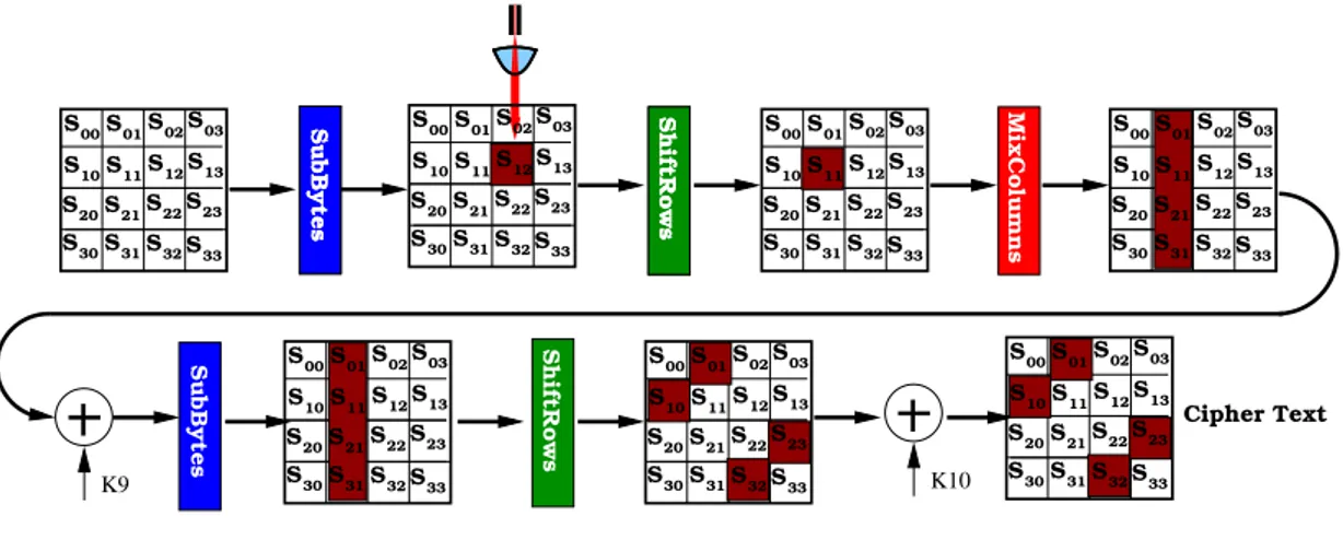
Analyse des effets de l’erreur
L’erreur touche un octet unique dans une colonne de la matrice d’état ShiftRows et SubBytes ne propage pas l’erreur Mais la transformation MixColumns affecte le reste des octets de la colonne. La figure1.3illustre la propagation d’une erreur qui tombe dans le tour 9 . S00S01S02S03 S12 S11 S13 S21 S20 S22S23 S30S31S32S33 S10 SubBytes S00S01S02S03 S12 S11 S13 S21 S20 S22S23 S30S31S32S33 S10 00 00 00 00 00 00 00 00 00 11 11 11 11 11 11 11 11 11 SubBytes S00S01S02S03 ShiftRows S12 S11 S13 S21 S20 S22S23 S30S31S32S33 S10 00 00 00 00 00 00 00 00 00 11 11 11 11 11 11 11 11 11 S00S01S02S03 S12 S11 S13 S21 S20 S22S23 S30S31S32S33 S10 00 00 11 11 00 00 00 11 11 110000 00 11 11 11 00 00 00 11 11 11 K9 S00S01S02S03 S12 S11 S13 S21 S20 S22S23 S30S31S32S33 S10 00 00 00 11 11 11 00 00 11 1100 00 11 11 00 00 00 11 11 11 K10 ShiftRows MixColumns ShiftRows S00S01S02S03 S12 S11 S13 S21 S20 S22S23 S30S31S32S33 S10 S00S01S02S03 S12 S11 S13 S21 S20 S22S23 S30S31S32S33 S100000 00 11 11 11 00 00 11 11 Cipher Text SubBytes
Figure 1.3: Erreur dans le tour 9
On remarque que l’erreur qui affecte l’octet S12 de la colonne 2 peut nous donner
l’information sur quatre octets de la clés K01, K10, K23, K32. En utilisant trois autres
fautes qui affecte les trois autres colonnes on peut avoir de l’information sur les 16 octets de la clé. Donc pour casser la clé, il faut avoir 4 paire de messages.
Analyse de l’information de l’erreur
Soit C un message chiffré sans erreur et D un message chiffré avec une erreur dans le tour 9 donc E = C ⊕ D représente l’erreur, et on trouve que dans E il y a quatre octets non nulle[? ],qu’on peut exploiter pour trouver quatre octets de la clé comme suit:
1. Preparer une liste Ldqui contient 1020 différences possibles de MixColumns du
Round 9 (255 x 4).
2. Faire une recherche exhaustive sur les KN r
0,d, K1,(d−1)mod4N r , K2,(d−2)mod4N r , K3,(3−d)mod4N r .
3. Calculer ∆t= SubBytes−1((C ⊕ KN r)∗,d) ⊕ SubBytes−1((D ⊕ KN r)∗,d)
4. Voir si ∆t∈ Ld
5. Si oui ajouter les quatre octets de la clé à la liste Cddes candidats possibles
6. Retour à l’êtape 2 avec une autre paire jusqu’a avoir un seul candidat.
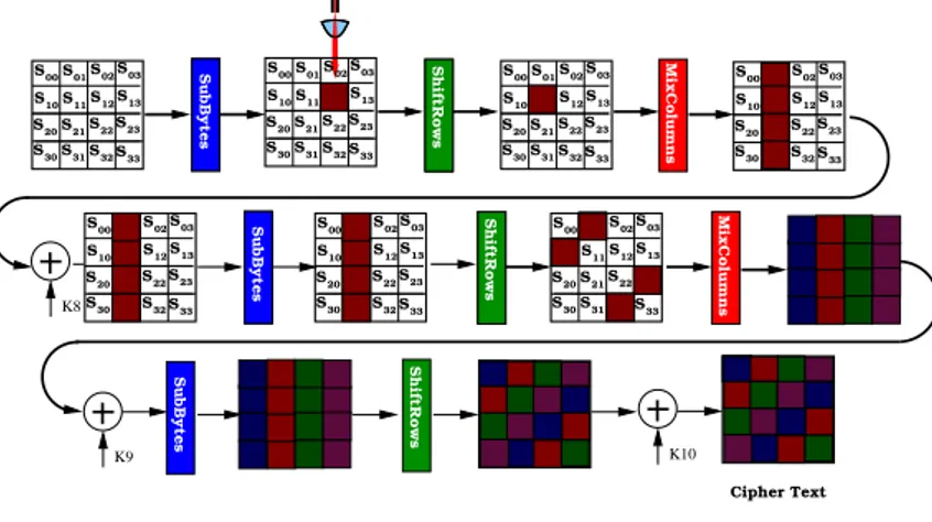
On remarque qu’on utilise 4 paires de message pour trouver les 16 octets de la clé. Mais on peut faire d’une pierre quatre coups en injectant l’erreur dans le Round 8, et c’est la transformation ShiftRows qui va affecter les quatre colonnes de la matrice,puis c’est la transformation MixColumns qui affecte toute la matrice comme le montre la figure1.4.
K8
SubBytes ShiftRows
SubBytes ShiftRows MixColumns
SubBytes ShiftRows K10 K9 S00S01S02S03 S12 S11 S13 S21 S20 S22S23 S30S31S32S33 S02 S12 S11 S13 S21 S30 S32S33 S02 S12 S11 S13 S21 S30 S32S33 S00S01S02S03 S12 S11 S13 S21 S20 S22S23 S30S31S32S33 S10 S00S01S02S03 S12 S11 S13 S21 S20 S22S23 S30S31S32S33 S10 S00S01S02S03 S12 S11 S13 S21 S20 S22S23 S30S31S32S33 S10
SubBytes ShiftRows S00S01S02S03 MixColumns
S12 S11 S13 S21 S20 S22S23 S30S31S32S33 S10 S00S01S02S03 S12 S11 S13 S21 S20 S22S23 S30S31S32S33 S10 S00S01S02S03 S12 S11 S13 S21 S20 S22S23 S30S31S32S33 S10 Cipher Text SubBytes ShiftRows
Dans la logique séquentielle, un signal global, appelé l’horloge, cadence tous les cal-culs combinatoires. Toutes les portes devraient avoir fini de propager leurs don-nées lorsque le front montant d’horloge arrive. Ce qu’on appelle le temps de setup, correspond à la période d’horloge la plus petite recevable.Si pour une raison quel-conque la période d’horloge est inférieur au temps de setup, des erreurs dans le cal-cul peuvent apparaître. Puisque temps de propagation augmente avec la diminution de l’alimentation diminuer la tension d’alimentation peut provoquer des violations de temps de setup comme le montre la figure 1.5. Le délai de propagation, ainsi qu’un second élément, inhérent à l’échantillonnage des bascule D, appelé temps de stabilisation “Setup-time” définisse la fréquence maximale du circuits. En effet afin d’assurer un fonctionnement normal du circuit, la période d’horloge doit être stricte-ment supérieur au délai de propagation maximal du circuit Tclk > Tcritique + Tsetup.
Le sur-cadencement “overclocking” consiste à diminuer la période d’horloge et si les
Setup violated
Setup met
Q’ Q D Q’ Q Dclk
clk
V cc ↓ ⇒
T
propagation↑
Figure 1.5: Violation de temps de setup
délais de stabilisation ne sont pas respectés. Cela a pour effet de stabiliser des fausse donnés d’ou l’injection de faute dans le système.
Plate-forme d’acquisition
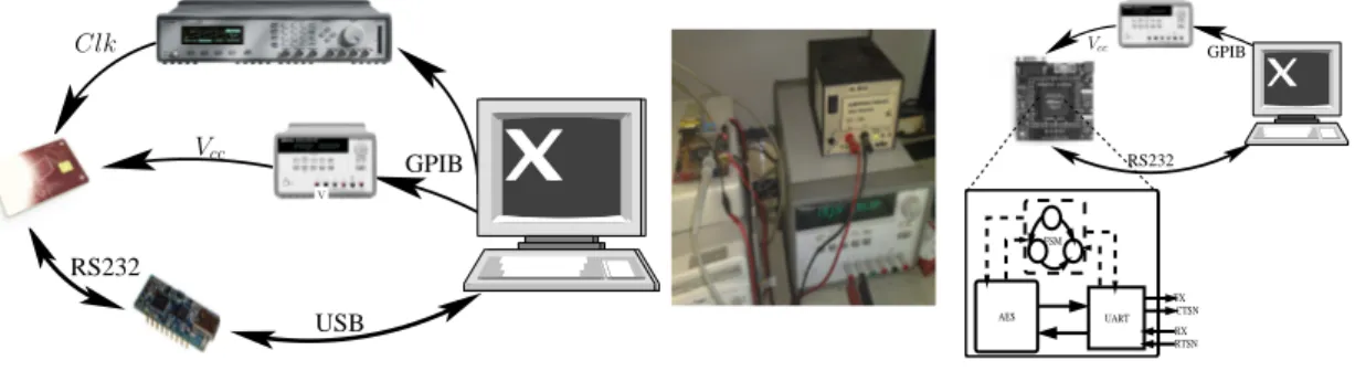
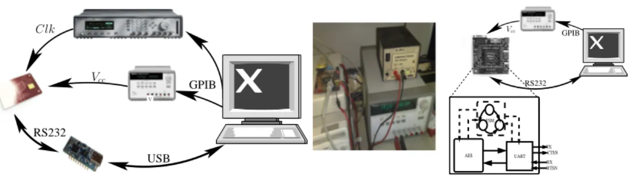
A fin d’injecter les fautes on a développé une plate-forme qui permet de changer la ten-sion d’alimentation et la fréquence d’horloge. La plate-forme consiste en une commu-nication régulière entre un terminal RS232 et le circuit, l’alimentation et la fréquence de l’appareil sont également contrôlables à distance, de telle manière différentes valeurs
de fréquence et de tension peuvent être testés successivement. La figure1.6montre le dispositif d’injection de fautes. Pour chaque valeur de tension on enregistre la valeur de la clef, le message et le chiffré.
V GPIB RS232 USB Vcc Clk RS232 GPIB FSM RX RTSN TX CTSN UART AES Vcc
Figure 1.6: Plate-forme d’injection de fautes
Analyse
Afin d’analyser les fautes, nous supposons que le message et la clé sont connus par l’attaquant et nous utilisons une implémentation en C++ de AES adaptés pour pouvoir corrompre un octet de la matrice d’état à n’importe quel tour de chiffrement.
Attaque sur ASIC
Une première attaque sur le circuit SecMat V1 a été réaliser par:
1. Diminution de la tension d’alimentation a une fréquence nominal de 32 Mhz, 2. Augmentation de la fréquence a une tension d’alimentation nominal de 1.2 V, On a progressivement augmenté le niveau de stress du circuit, et on remarque que l’attaquant peut choisir précisément la quantité de fautes induites dans le circuit. La figure 1.7et1.8montre qu’il existe une plage confortable de la tension et de fréquence vulnérables où le circuit cryptographique fait sortir des résultats erronés.
Attaque sur FPGA
Architecture du SOC
A fin d’attaquer AES sur FPGA nous avons réalisé un circuit cryptographique que nous avons synthétisé sur Altéra Stratus et Filin Vortex5. Le circuit est composé de
0 10 20 30 40 50 60 760 770 780 790 800 810 820 830 Occurrence [%] Voltage [mV] Majority of single errors Majority of multiple errors
Figure 1.7: Occurrence des fautes —
(tension). 0 10 20 30 40 50 60 60 61 62 63 64 65 66 67 68 69 70 Occurrence [%] Frequency [MHz] Majority of single errors Majority of multiple errors
Figure 1.8: Occurrence des fautes
(fréquence).
trois modules: une interface UART, un contrôleur et coprocesseur AES. Trois dif-férentes implémentations du module Sbox de aes on été réalisés. Dans la première on a utilisé les LUT’s de l’FPGA ,dans La deuxième implémentation on a utilisé la RAM de l’FPGA et dans la dernière implémentation on utilise une factorisation de la Sbox dans GF4 . Finalement, on a réalisé l’attaque par violation de setup sur les
différentes architectures.
Résultat sur Altera Stratix
Le tableau1.1montrer la localisation temporelle et spatial des fautes simples dans l’ FPGA Stratix d’Altera. On peut voir qu’il y a suffisamment de fautes simples qui arrivent dans les deux avant-dernier tours pour réaliser l’attaque de Gilles piret. On remarque que comme pour l’ASIC que les fautes ne sont pas uniformément répartis.
Comparaison Altera Stratix et Xilinx Virtex
La figures1montrent la fréquence d’apparition apparition des fautes simples dans les trois architectures d’ Altera et de Xilinx. Seul les fautes simple qui affecte un octet avant la transformation Sbox sont affiché on remarque que les trois architectures sont vulnérable face au attaque par violation de setup.
En se référant au tableau1.2on remarque que le chemin critique dépend de l’architecture de la sbox implémentée. On peux voir aussi que l’architecture LUT a plus de fautes simple dans altera que dans Xilinx par contre on observe l’inverse pour l’implémentation
Table 1.1: Localisation temporelle et spatial de fautes simples dans Altera Stratix
LUT
0 5 10 15 20 25 30 35 R10 R9 R8 R7 R6 R5 R4 R3 R2 R1 % of faults Round Temporal localization 0 10 20 30 40 50 60 S15 S14 S13 S12 S11 S10 S9 S8 S7 S6 S5 S4 S3 S2 S1 S0 % of faults Sbox Spatial localizationRAM
0 2 4 6 8 10 12 14 16 18 20 R10 R9 R8 R7 R6 R5 R4 R3 R2 R1 % of faults Round Temporal localization 0 10 20 30 40 50 60 70 80 S15 S14 S13 S12 S11 S10 S9 S8 S7 S6 S5 S4 S3 S2 S1 S0 % of faults Sbox Spatial localizationGF
(2
4)
0 5 10 15 20 25 30 R10 R9 R8 R7 R6 R5 R4 R3 R2 R1 % of faults Round Temporal localization 0 5 10 15 20 25 30 35 40 S15 S14 S13 S12 S11 S10 S9 S8 S7 S6 S5 S4 S3 S2 S1 S0 % of faults Sbox Spatial localizationShiftRows MixColumns SubBytes AddRoundKey Key Expansion Round Key Register Register Reset AES CONTROL Control Start Done Data Round Message Clock Critical Path Cipher
Figure 1.9: Architecture du cryptoprocesseur AES
dans la RAM. On remarque aussi que dans l’ FPGA Xilinx les fautes simple commence a apparaître a des tensions plus basse que dans Altera.
Attaque optique
Plate-forme d’attaque
L’idée d’injection de fautes optiques a été présenté par S.Skorobogatov et R.Anderson en 2003 [2]. Ils ont montré qu’il est possible de modifier le contenu de la mémoire sta-tique par la lumière. Pour réalise les différentes campagnes d’injection de fautes par tir laser nous utilisons une plate-forme laser composée d’une table XYZ, une caméra, deux lasers un vert de longueur d’onde 532 nm et un autre infrarouge de longueur d’onde 1064 nm et d’un générateur de basse fréquence pour contrôler la durée du tir
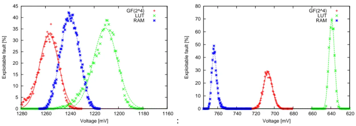
0 5 10 15 20 25 30 35 40 45 1160 1180 1200 1220 1240 1260 1280 Exploitable fault [%] Voltage [mV] GF(2^4) LUT RAM
Figure 1.10: Occurrence des fautes simple
dans Altera Stratix.
: 0 10 20 30 40 50 60 70 80 620 640 660 680 700 720 740 760 Exploitable fault [%] Voltage [mV] GF(2^4) LUT RAM
Figure 1.11: Occurrence des fautes simple
dans Xilinx Virtex5.
Table 1.2: Altera Vs Xilinx
Architecture Temps critique(ns) % faute simple Surface Voltage FPGA Altera Xilinx Altera Xilinx Altera Xilinx Altera Xilinx
LUT 13.725 7.772 39 % 69 % 0.872 0.513 1.21 0.64
RAM 17.569 9.758 42 % 29 % 0.795 0.282 1.26 0.71
GF(24) 18.818 14.426 33 % 50 % 0.635 0.335 1.24 0.76
laser. L’ensemble du système est contrôlé par un programme qu’on a développé1.12. La taille du spot laser est de 5 µm ce qui nous permet de cibler une petite zone du composant attaqué. Pour injecter les fautes une étape de préparation du composant est nécessaire c’est ce qu’on appel la décapsulation. Deux type de préparations peu-vent être effectués sur le composant: une préparation chimique et une préparation mécanique. Cette étape permet au faisceau blaser d’atteindre la couche de silicium sans perdre beaucoup d’énergie. Le circuit qu’on a attaqué est un admet Armera128 qui implémente l’algorithme AES.
Résultat
On a réalisé plusieurs tentative d’injection en variant la puissance du laser et la zone d’injection finalement on réussit a trouvé une zone sensible autour d’un bus de donnée dans la flash. En utilisant un trigger qui déclenché le tir laser on a réussit a injecter
USB
RS232
Figure 1.12: Plate-forme d’injection optique
des fautes dans l’avant dernier tour du chiffrement. Une analyse des fautes injectées a montrés que c’est des collages de type "stuck-at". la figure1.13montre la cartographie des fautes. Freeze Fault Free Freeze SEU MEU 0xd2 0x83 0x7d
Contre-mesure
Vue l’importance des applications qui utilisent cette algorithme, il est nécessaire que les implémentations intègrent des solutions efficaces. Les contre-mesures sont tou-jours possibles et disponibles, mais elles doivent être bien pensées pour ne pas faire d’autre faille qui seront peut être exploiter dans le future. La plus part des solutions qu’on trouve dans la littérature se base sur deux principes, redondance spatiale et redondance temporelle.
Détection
C’est une contre-mesure proposée pour l’AES par Ramish. Karri [3]. Le principe est de déchiffrer chaque groupe de transformations en parallèle du chiffrement et de com-parer la sortie du déchiffrement avec l’entrée avant le chiffrement. Il y a dans ce cas une double perte en terme de surface et de temps : un Sur-coût en surface de l’ordre de la duplication puisque chaque la sortie de chaque module doit être décodée, et un Sur-coût en temps puisque chaque élément doit être mémorisé pour être comparé avec le même élément codé et décodé.
Code robuste non-linéaire
Cette technique consiste à calculer pour chaque colonne de la clé et du message une signature sur 32 bits qui va nous permettre de détecter les erreurs, La signature est calculée à chaque cycle en utilisant une colonne de la clé du ronde. Le calcul de la signature ce fait en utilisant un prédicteur linéaire, puis un compresseur linéaire qui permet de réduire la signature de 32 bit à Slbits tel que Sl< 32 . La signature est cubé
X3 dans GF2 pour produire une signature non linéaire comme la sortie d’une ronde
de l’AES. Une fois la signature originale obtenue on utilise un réseau de détection d’erreur(EDN) qui va permettre de calculer à partir de la sortie du ronde une autre signature qui sera comparer avec la signature final et ainsi détecter les erreurs [4]. Cette méthode de détection est très efficace car elle permet de protéger l’algorithme contre les attaques qui vise le datapath comme celle de Piret et les attaque qui vise l’expansion de la clé et elle permet de détecter les erreurs à la volée. Mais elle induit une augmentation considérable dans la surface du circuit. La figure1.14illustre cette contre mesure:
32 bits R bits R bits 32 bits R bits Key Round i EDN AES Round Error Key Schedule Compressor Linear Compressor Predictor Linear ShiftRows/Inv X^3 X^3 MixColumns/inv
Figure 1.14: Code robuste non-linéaire
Résilience
Une autre stratégie pour contrer les attaques en fautes est la résilience, elle consiste a laisser la faute se propager dans le circuit tout en empêchant l’attaquant d’avoir un résultat exploitable pour pouvoir monter une DFA a fin de retrouvé la clé de chiffre-ment. Contrairement aux techniques classique de détection d’erreur, cette nouvelle approche autorise le circuit à continuer son calcul et a fournir un résultat faux,tant que ce résultat ne porte pas d’information utile pour retrouvé le secret. on propose dans cette thèse deux solution pour contré les attaques en fautes.
Niveau protocole
A fin de réaliser une attaque en faute, l’attaquant a besoin de chiffré deux fois le même message avec la même clé. Donc si on arrive a l’empêcher d’avoir ce couple de chiffrement faux et correcte. il ne sera pas capable de faire une DFA même si il réussi a injecter une faute dans le calcul. Pour implémenter ce niveau de résilience il suffit de modifier le message en lu ajoutant de l’aléa comme le montre les algorithmes suivants:
Algorithm 1: Chiffrement probabiliste
Générer un message aléatoire r de même taille que x. 1
Envoyer le couple (y = AESk(x ⊕ r), r).
2
Algorithm 2: Déchiffrement Déterministe. Déchiffrer y avec k: z = AES−1
k (y).
1
Envoyer z ⊕ r = x. 2
Niveau logique
Une autre méthode pour implémenter la résilience c’est d’utiliser la logique DPL. En effet cette technique est utilisée généralement comme contre-mesure contre les at-taques passives possède des propriétés de résilience. En effet il y a seulement deux états valide (0, 1) et (1, 0) donc si on injecte une faute simple on obtient deux états invalides NULL0 (0, 0) et NULL1 (1, 1) comme le montre la figure1.15. Vue que les algorithmes cryptographiques possèdent une grande propriété de diffusion, ces états invalides se propagent dans toute la net-liste pour effacer tout l’information utile ce qui empêche un attaquant de réaliser une DFA.
A fin de validé cette contre mesure on a réalisé une implémentation en WDDL d’un AES puis une attaque par violation de temps de setup sur le circuit. Une observa-tion intéressante est que a chaque fois qu’un octet est affecté par une fautes, un octet nul apparaît dans le texte chiffré a la place du bon octet. Cela signifie que même après avoir réussi à injecter la faute lors du chiffrement et de connaître précisément l’emplacement de la faute, la sortie ne donne aucune information qui peut être ex-ploiter pour récupérer la clé de chiffrement. Par conséquent, une conception WDDL
NULL0
VALID1
NULL1
VALID0
Precharge:
Evaluation:
(output disclosed )
Figure 1.15: protocole DPL0 10 20 30 40 50 60 70 80 90 100 1900 1910 1920 1930 1940 1950 1960 Occurrence [%] Voltage [mV] Faults Single errors Multiple errors
Figure 1.16: occurrence des fautes dans une version wddl d’AES
contre si l’attaquant arrive a injecter une faute symétrique (1, 0) → (0, 1) la logique DPL n’est pas capable d’assurer la protection du circuit mais en pratique il est presque impossible d’introduire ce type de fautes.
conclusion
Dans cette thèse, nous présentons différents aspects d’attaque sur les implémenta-tion cryptographique de l’algorithme de chiffrement AES, ainsi qu’une étude sur les contre-mesures possibles.
La première méthode d’injection de fautes est une nouvelle technique pour injecter des fautes globales cette technique est non-invasive basée sur la violation temps de setup. Nous avons démontré que cette méthode globale permet l’injection de fautes aléatoires dans le circuit . Malgré que nous ne contrôlons pas le temps et le emplace-ment de l’injection de la fautes, On arrive a obtenir suffisamemplace-ment de faute pour réaliser les attaques en fautes. Nous avons montré que cette attaque peut être réalisé sur les circuits ASIC et FPGA. On a aussi réalisé une attaque locale sur un microprocesseur Atmel ATmega128 en utilisant un laser.
Nous présentons aussi dans cette thèse, une nouvelle approche pour contré les at-taque en fautes basé sur la résilience. La résilience n’impose aucune destruction des secrets dans le cas d’une attaque par faute. Dans une implémentation protégée par résilience, quand une faute est injecté avec succès mais n’a pas de conséquence dans le calcul, le circuit ne présente aucune réaction à la faute par contre un circuit protégé par un système de détection arrête automatiquement le calcul même si la faute n’a pas d’effet. Dans une implémentation résiliente même si la faute est injectée lors du calcul l’attaquant ne peut pas exploiter le résultat a fin d’exécuter une attaque DFA.
Plusieurs méthodes concrètes pour mettre en oeuvre la résilience pour les chiffre-ments symétriques sont proposées, parmi lesquelles un mode aléatoire de fonction-nement qui convient pour des cartes à puce a faible coût. Nous proposons d’utiliser les logiques DPL comme méthode de protection. Ces logiques protègent simultané-ment contre les attaques par observation et par perturbation, et sont moins coûteux que la détection basée sur les codes.
Nowadays, digital information is more and more important in our information soci-ety and it is necessary to protect such sensitive information using cryptographic algo-rithms. Those cryptographic systems are often implemented in hardware to increase the throughput of information. When cryptographic systems can be accessed phys-ically no one is sure of the security of transferred information. Indeed attacks that target directly the physical implementations can be devised.
This kind of attacks is known as “side channel attacks” (SCA). They can be classified in two types: active and passive, both of which providing enough information to fully compromise the security. The devices that are concerned are, for instance, smartcards (pay-TV cards, SIMs, etc.) or handheld terminals (mobile phones, PDAs, etc.).
The first type of SCA is called passive attack and consists in observing physical em-anations of the system, like power (Differential Power analysis, or DPA [5]) or Elec-troMagnetic field (ElecElec-troMagnetic Analysis, or EMA [6]). An off-line analysis of the physical measurements allow to extract the full key, by correlation or pattern matching techniques.
The second type of attacks is called active attack and consists in injecting faults during the execution of a cryptographic algorithm. Faults attacks can of course be used to obtain DoS (Denial of Services). But the real strength of fault attacks is that they enable an attacker to retrieve secret information concealed within the device [7]. From the knowledge of one or multiple couples {correct ciphertext, faulted ciphertext}, some hypotheses on the secret key can be discarded. This generic attack strategy is referred to as DFA (Differential Fault Analysis). Although active attacks were reported later (in 2001 [8]) than passive attacks (in 1998 [5]), many attacks have been published, which show how very few errors can break even the most secure cryptosystems: The
most astounding results are the Bellcore attacks against RSA, where a single faulty signature may reveal the secret key, and AES, where only two well localized faults can break the cipher.
There are several techniques known for fault injections in a system: The variations of the supply voltage, the clock frequency, the temperature variation, or the irradiation by a laser beam will most probably lead to a wrong computation result that can be exploited to realize DFA.
This kind of attack represents a greater threat for the implementation of crypto-graphic algorithms such as the AES and RSA than passive attacks.
This thesis concentrates on one specific side-channel namely faults. Here, an adver-sary induces faults into a device, while it executes a known program, and observes the reaction. The adversary has to tamper with an attacked device in order to create faults, thereby opening the desired side-channel.
The main propose of this work is to validate the feasibility of fault attacks and to implement some countermeasure to protect crypto processors. This thesis work is recorded in three chapters. The outline of the thesis is as follows:
• In chapter 1 we introduce cryptography, side channel attacks and state of art of fault attacks.
• In chapter 2 we give a new method to inject global faults in both ASICs and FPGAs, then we show local optical semi invasive attacks on software implemen-tation of AES.
• In chapter 3 we present fault attack countermeasure and discuss a new method of protection based on resilience, then we study the resilience on WDDL.
• Finally, in chapter 4 we conclude by an overall review on this work and open some perspectives to improve it.
Physical Attack On Cryptographic
Implementation
Standardized cryptographic algorithms are basically secure against algorithmic at-tacks. But once such algorithms are implemented, either on dedicated hardware or as software on a micro-controller, different physical properties of the algorithm can be observed. Over the years, sophisticated attacks have been developed that enabled attackers to break cryptographic devices by such observations. In this chapter, we in-troduce the basic principles of cryptographic algorithms and we show how its physical implementation can be exploited.
First, we will describe some general principles, such as symmetric ciphers and public-key schemes. Then we will give an overview of cryptanalytic techniques aimed at breaking the most used cryptosystems. We will focus our attention on active at-tacks. In practice, we present attack methodologies based on intentional injection of errors during the computation process, describing how we can inject such faults and the most common attacks to exploit faulted results.
2.1 Cryptography
The prefix of the “cryptology” stems from the Greek root crypto that means “hiding”. Cryptology include two branches “cryptography” and “cryptanalysis”. Cryptogra-phy provides methods to transform legible information (plaintext) into a form that is protected (ciphertext) with the help of a secret information (cipherkey). Any informa-tion related to cryptographic system can be public except the key. While cryptanal-ysis provides methods to extract the “cipherkey”. Cryptography is used nowadays
in a large variety of domains. Information is now created, transmitted and stored in an electronic form and this sensitive data must be protected from unauthorized use. This can be easily accomplished through cryptographic systems which can be roughly divided into two main classes: symmetric ciphers and public-key algorithms. The symmetric algorithms use the same private key to cipher and decipher, on the other hand, public key cryptography requires a pair of keys private for decipher and public to cipher message .
2.1.1 Symmetric Ciphers
Symmetric ciphers are the oldest and most common algorithms in cryptography. One of the simplest forms is known as the Caesar cipher ”reputedly used by Julius Caesar to conceal messages” in which the process is simply one of shifting the alphabet by so many places in one direction or another. Symmetric ciphers accept a plain input text and a secret key and return an encrypted output text.
Usually, the algorithm is made of two distinct processes: a data-path, where the initial input is processed and mixed with the key and a key schedule, which is used to obtain the whole needed key material starting from the secret key. The algorithms are mostly iterative, which means that a few simple operations are repeated for a certain number of times; at the same time, for each iteration (called round) the key schedule computes a round key which will be used only once.
Decryption is computed using the same encryption key: usually, the decryption process is the execution in the reverse order of the inverse functions of the encryption data-path, although in some cases the same algorithm can be used (these are called involution ciphers such as NOEKEON [9] ). The key schedule, however, must still provide key material in the reverse order, which means that the key must be com-pletely unrolled before decryption can start. Sometimes, the key schedule is executed before the encryption and the key material is stored into memory for future use; al-ternatively, if allowed by the cipher structure, it can be executed in parallel with the encryption process (on-the-fly).
Symmetric ciphers are partitioned into two categories. When the input data is pro-cessed one bit or byte at a time, then the algorithm is called stream cipher. When the input is a block of few bytes, it is a block cipher. The variety of symmetric block ciphers
available in the literature, in the industry and on the market, is huge. They constitute the simplest way to protect a transmission, which led many parties to implement their own proprietary encryption scheme and keep it jealously secret. In the most ancient one, the robustness of the encryption scheme relies on the secrecy of the key, but also on the secrecy of the algorithm. Such practice is against the Kirchhoff’s principle, stat-ing that the security must rely only on the key. If the algorithms specifications leak and become public, chances are that the scheme is no longer secure: this happened with the Content Scrambling System [10], the protection scheme used on commercial DVDs. Luckily, the recent trend is to develop public algorithms, which are therefore given to the community of researchers, who can find possible weaknesses.
Symmetric cryptography normally requires the key to be shared and simultane-ously kept secret within a restricted group. It is simply not possible for a person who views the encrypted data with a symmetric cipher to be able to do so without having access to the key used to encrypt it in the first place. If such a secret key falls into the wrong hands, then the security of the data encrypted using that key is immediately and completely compromised. Hence, what all systems in this group of secret key methods share is the problem of key management.
The most common symmetric block ciphers are DES and AES.
2.1.1.1 Data Encryption Standard
As presented in the FIPS standard1 this algorithm is designed to encipher and
de-cipher blocks of data consisting of 64 bits under control of a 64-bit key of 56 bits of entropy. Deciphering must be accomplished by using the same key as for encipher-ing, but with the schedule of addressing the key bits altered so that the deciphering process is the reverse of the enciphering process.
1Federal Information Processing Standards (FIPS) are publicly announced standards developed by
the United States Federal government for use by all non-military government agencies and by govern-ment contractors. Many FIPS standards are modified versions of standards used in the wider commu-nity (ANSI, IEEE, ISO, etc.) Some FIPS standards were originally developed by the U.S. government. For instance, standards for encoding data (e.g. country codes), but more significantly some encryption standards, such as the Data Encryption Standard (FIPS 46) and the Advanced Encryption Standard (FIPS 197).
A block to be enciphered is subjected to an initial permutation IP, then to a complex key-dependent computation and finally to a permutation which is the inverse of the initial permutation IP−1. Figure2.1shows the DES algorithms.
The key-dependent computation can be simply defined in terms of a function f, called the cipher function, and a function KS, called the key schedule [11].
R15 L15 R15 L16 R0 L0 S0 S7 S6 S5 S S3 S2 S1 R1 L1 IP IP Key Key16 2 32 32 64 64 48 48 48 f f Key1 f 48 32 32 32 P E Key 32 32 32 32 48 6 4 6 4 6 4 6 4 6 4 6 4 6 4 4 6 4 Plaintext Ciphertext −1
Figure 2.1: Data Encryption Standard
Data can be recovered from cipher only by using exactly the same key used to encipher it. Unauthorized recipients of the cipher who know the algorithm but do not have the correct key cannot derive the original data algorithmically. However, anyone who does have the key and the algorithm can easily decipher the cipher and obtain the original data. A standard algorithm based on a secure key thus provides
a basis for exchanging encrypted computer data by issuing the key used to encipher it to those authorized to have the data. Selection of a different key causes the cipher that is produced for any given set of inputs to be different. But with the increase of the computation speed in new computers this key can be found in few minutes using brute force attack (which means a trial of all possible values of the key). In fact, in June 1997 the DES was cracked by a federation of hackers that were using a network of normal computers and it took 23 hour and 15 minutes [12]. This motivated the need for a more robust encryption mechanism has been performed especially that this algo-rithm is used in important economic transactions and governmental communications. The first idea was to use 3DES which consists in using a call of DES, then −DES−1,
and finally DES. But being aware of the weakness of the DES, the NIST2 made an
invitation to tender to work out a new standard.
2.1.1.2 Advanced Encryption Standard
In 2 October 2000, the NIST has chosen between the seven final candidates, and that was the ‘‘Rijndael” algorithm that won the competition and became the new Encryp-tion standard algorithm AES [1].
AES is an encryption algorithm invented by two Belgians researchers Joan Daemen and Vincent Rijmen. The AES algorithm proceeds by block of 128 bits, and a key of variable length. The length 128, 192, 256 allows a trade off between security and efficiency.
AES is an iterative algorithm, the number of rounds depend on the length of the key, for a 128-bit key length the number of round is equal to 10 rounds, 12 for 192-bit key and 14 for 256-bit key.
Furthermore, AES encryption and decryption are based on four different transfor-mations that are performed repeatedly in a certain sequence. Each transformation maps a 128-bit input state into a 128-bit output state.The transformations are grouped
2The National Institute of Standards and Technology (NIST), known between 1901 and 1988 as the
National Bureau of Standards (NBS), is a non-regulatory agency of the United States Department of Com-merce. The institute mission is to promote U.S. innovation and industrial competitiveness by advancing measurement science, standards, and technology in ways that enhance economic security and improve quality of life.
in rounds. The rounds are slightly different for encryption and decryption. These transformations are described in the Figure2.2.
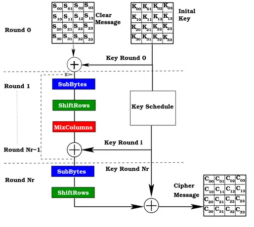
K00K01K02K03 K12 K11 K13 K21 K20 K22K23 K30K31K32K33 K10 S00S01S02S03 S12 S11 S13 S21 S20 S22S23 S30S31S32S33 S10 MixColumns ShiftRows ShiftRows SubBytes C00C01C02C03 C12 C11 C13 C21 C20 C22C23 C30C31C32C33 Message Message Cipher Key Round i Key Round Nr Key Round 0 Round 1 Round Nr−1 Round Nr C10 Inital Key Clear Round 0 SubBytes Key Schedule
Figure 2.2: AES encryption
In the AES, the 128-bit data block is considered as a 4 × 4 array of bytes called state matrix. The algorithm consists of an initial data/key addition, 9 full rounds (when the key length is 128 bits), and a final (modified) round. A separate key scheduling module is used to generate all the keys, or round keys, from the initial key; a sub-key is also represented as 4 × 4 array of bytes. The full Rijndael round involves four steps:
1. a non-linear substitution that is applied on the state matrix: « SubBytes ». 2. A circular bytes permutation within the same line: « ShiftRows »
4. A simple XOR with the output of the key register: « AddRoundKey ». SubBytes Transformation
The SubBytes transformation replaces each byte in a block by its substitute from an S-box as shown in figure 2.3. The Sbox is an invertible substitution table which is constructed by a composition of two transformations:
• First, each byte Ai,jis replaced with its reciprocal in GF (28)(except that 0, which
has no reciprocal, is replaced by itself).
• Then, an affine transformation f is applied.
Figure 2.3: SubBytes transformation [1].
The S-box is usually implemented as a look-up table consisting of 256 entries, each entry is 8 bits wide, but it also can be computed “on-a-fly”.
ShiftRows Transformation
Next comes the ShiftRows transformation, each row in a 4 × 4 array of bytes of data is shifted 0, 1, 2 or 3 bytes to the left in a round fashion, producing a new 4 × 4 array of bytes as shown in figure2.4.
MixColumns Transformation
The MixColumns transformation, operates on each column individually as shown in figure2.5. Each byte is mapped into a new value that is a function of all four bytes in the column. The transformation can be defined as a matrix multiplication on the state, each column is treated as a polynomial over GF (28)and is then multiplied modulo
x4+ 1with a fixed polynomial a(x):
a(x) = (0x03)x3+ (0x01)x2+ (0x02)x + (0x02)
Figure 2.5: MixColumn transformation [1].
AddRoundKey Transformation
The final transformation is AddRoundKey, it simply XOR-es the result with the sub-key for the current round as shown in the following figure2.6
The Key Schedule
Each round accepts a round key derived from the initial secret key by means of the Key Schedule process as described in figure2.7.
• ”Rotword” operation takes a 32-bit word and rotates it by eight bits to the left. • ”Subword” operation uses S-Box table to replace each byte of the columns. • ”Rcon” is a table of constants depending on the round number.
More precisely, if k0is the secret key and kiis the ithround key, then Key Schedule
computes ki = KS
i(ki−1)as a function of the previous round key. The functions KSi
themselves depend on the round and on the size of the key. However, the KSi do not
Figure 2.6: AddRoundKey operation
2.1.2 Asymmetric Cryptography
Symmetric ciphers are highly efficient from the computational point of view, but they have an important issue: key management is extremely inefficient. First of all, the secret key must be exchanged securely and the encryption of the secret key is not an option, since it would represent the same problem again and again. If the key gets leaked, then it should be revoked and new one should be shared. In addition to this, each different secure link requires its own key: every pair of users should be assigned a unique key, known only to the authorized owners, which means that the overall number of keys would grow exponentially. Even if the key is shared within a single group of people, there would be no way to identify correctly the sender within the group, or have a subset of authorized receivers.
Public-key (asymmetric) cryptosystems are the solution to these issues. Each user has a pair of keys: a secret key (the private key) and a second public key. The keys of each pair are related to each other: it is easy to compute the public key from the pri-vate key, but the inverse is computationally infeasible. Thus, each user can generate a (random) public key, which will be posted publicly and then compute his secret key; other users will be able to know only the public key, and will be unable to invert the process to obtain the user’s secret key. What is encrypted with one of the keys, can be decrypted only using the other: for instance, if we use our public key to encrypt a message, it will be decrypted only by our private key. This scheme allows to provide some very important properties for secure communications:
Confidentiality: it is the guarantee that the message will not be read by an unautho-rized user; it can be achieved by encrypting the message with the public key of the receiver, thus we can guarantee that only his private key will allow decryption. Authentication: it is the proof of the sender’s identity, certifying that the sender of the message is actually the one who claims to be; it can be achieved by encrypting the message with the private key of the sender. It will be decrypted only with the public key of the sender, revealing his identity.
Non-repudiation:it is strictly related to the previous concept and means that the sender can not deny having sent the message. It is based on the assumption that the private key is known only to its legitimate owner and that it can not be inferred from the pub-lic key. Thus, the message could not be sent by any other user.
is exactly the message that was transmitted at the source. It is usually achieved by attaching a digest of the message itself, usually the result from a commonly shared hashing algorithm; then, the digest only can be encrypted with the sender’s private key. At the reception point, the receiver computes the digest of the message; then he decrypts the digest he got by using the sender’s public key and compares the results, proving that they were not modified. The system relies on the security of the hash-ing algorithm, i.e., the complexity of creathash-ing different messages with the same digest (collision attacks).
2.1.2.1 RSA
The most used public-key crypto system is RSA [13], based on modular exponenti-ation in finite ring Zn. Encryption is computed by exponentiating the message with
the secret or the public key, decryption is computed again by exponentiation with the other exponent. RSA is based on the problem of factoring the product of two large primes.
Algorithm 3: RSA Algorithm
1. Choose two distinct large primes p and q of the same bit length. 2. Compute N = p.q as the RSA modulus.
3. Let ϕ(N) = (p − 1).(q − 1) denote Euler’s totient function. 4. Choose a public key 3 < e < ϕ(N) − 2 coprime to ϕ(N)
5. Compute as the secret key the unique integer 1 < d < ϕ(N) such that e.d = 1 mod ϕ(N ).
• Encryption a message M ∈ ZnCompute C = Memod N.
• Decrypting a ciphertext C ∈ ZnCompute M = Cdmod N.
• Signature of a message M ∈ Zn, the signature S is created as S = Mdmod N.
• Verification of a signature S ∈ Znof a message M Se = M mod N.
2.1.2.2 Elliptic Curve Cryptography
Another method to define public key algorithms is to use elliptic curves [14]. In contrast to RSA, computations take place in a finite additive group. An elliptic curve E over field K is defined by the Weierstrass equation: E : y2+ a
1xy + a3y = x3+ a2x2+
a4x + a6. The set of points (x,y) ∈ K2as a solution of the equation E, together with the
point at infinity O form and additive abelian group. The point O is the neutral element of the group. It is denoted as E(Fp). The group operation is called addition for two
distinct points and doubling otherwise. An elliptic curve group operation consists of many field operations. For a field Fpwith a characteristic other than 2 the equation E
can be simplified to E : y2 = x3+ ax + b a, b ∈ K.In order to encrypt message using
order of E is divisible by a large prime q, then we chose a base point P on E of order q. Obviously the choice of E and P is crucial for the security of the system. The order of the base point P must be a large prime.
Algorithm 4: ECC Algorithm
1. Choose an elliptic curve E defined over Fp.
2. Choose a base point P on E of order q. 3. Choose the secret key k ∈ {1, 2, ..., q − 1} 4. Compute public key Q=k.P on E.
Encryption
• Choose a random session key r ∈ {1, 2, ..., q − 1}
• Compute the two points R=r.P=(x1, y1)and r.Q=(x2, y2).
• Compute C = x2+ M where M ∈ Zpis the message to be encrypted.
• Send out (R,C) =(x1, y1, C) Decryption • Compute (x′ 2, y2′) = k.R • Recover M = C − x′ 2
2.2 Smartcard Architecture
The trend for miniaturisation and portability of every computing device has led to the development of smartcards which is a small computing device as large as a credit card and equipped with processing unit, some memory and dedicated processors for cryptographic computations. The smartcard has a microprocessor embedded in it that, when coupled with a reader, has the processing power to serve many different appli-cations. By the means of cryptographic algorithm, smart cards make personal data available only to the appropriate users.
Since its commercial launch in 1992, the smart card has taken full advantage of the miniaturization of circuits and, although the maximum area of the chip is standard-ized to 25 mm2, the circuits have evolved to more computing capabilities. Smart cards
are used in combination with terminals; such as bank cards, prepaid phone cards or SIM, whose terminal is the mobile phone. Most of the time they are links in the chain of custody of a larger system. The industry has set standard ISO/IEC 7816 to facilitate interoperability of the smartcard and FIPS-140 to ensure the security of this compo-nent of cryptographic modules.
The integrated circuit as shown in figure2.8, may contain a microprocessor (CPU) capable of processing this information and specialized cryptographic hardware that uses algorithms such as RSA, 3DES or AES. Smartcard is mainly used as means of personal identification(identity card ,SIM card), payment service(credit card) or for prepaid services (phone card, pay-TV).
UART RAM Flash CPU clk rst vdd gnd io in te rn al b u s crypto-engine TRNG smartcard
Figure 2.8: Smartcard internal architecture
The smartcard have in general five pin-out:
• Vdd is the supply voltage that drives the chips at 5V, 3V or 1.8V.
• Gnd is the substrate or ground reference voltage against which the Vdd potential is measured.
• Reset is the signal line that is used to initiate the state of the integrated circuit after power on.
• IO input/output connector. This is the signal line by which the chip receives commands and interchanges data with the outside world.
• CLK is the clock signal is used drive the logic of the IC and is also used as the reference for the serial communications link.
Smartcards are extremely customizable and can be applied to a large variety of ap-plication domains, but on the other hand they are extremely vulnerable to physical attacks based on side channel information leakage. Next section will be dedicated to present physical attacks known as Side Channel attack “SCA”.
2.3 Side Channel Attack
Cryptosystems are usually implemented as embedded devices or software algorithms. Even if the cryptosystem is secure and without any apparent flaw, its implementation may reveal some useful information about the secret key in an indirect way. Kocher in [15] and in [16] published two novel attack techniques, witch exploit side chan-nel leakage of cryptographic devices. Computation requires time, consumes power and causes electromagnetic radiations: all these are possible sources of information related to secret key. These techniques are rather powerful, since they allow to reduce the complexity of an attack to several orders of magnitude, on the other hand, they require physical access to the device to collect the necessary measurements, while the computation phase of the attack can be done off-line.
2.3.1 Timing Attack
The timing attack was predefined opposed by Paul Kocher in 1996 [15]. The sim-plest concept of timing attacks is that the attackers exploit the observed different cution time between different instructions to see if some specific instruction was exe-cuted or skipped by Mich the attackers can extract the secret key.
Consider the flow of any program, programs always spend much time in compar-ison and conditional-jump. Each condition leads to distinct path. Therefore, if the attacker inputs different messages into a program, the time consumed will be slightly different for different inputs. Thus, the attacker can observe the variance in execu-tion time, and then obtain the secret key. For example,In RSA the execuexecu-tion time for the square-and-multiply algorithm used in modular exponentiation depends linearly on the number of ’1’ bits in the key. While the number of ’1’ bits alone is not nearly enough information to make finding the key trivially easy, repeated executions with
the same key and different inputs can be used to perform statistical correlation analy-sis of timing information to recover the key completely.
2.3.2 Power Analysis
Cryptographic devices are implemented using semiconductor logic gate, which are constructed out of CMOS. The electron flow across the silicon substrate when charge is applied to a CMOS’s gate consumes power and produces electromagnetic radiation. Further more, most power is consumed when the gate is in transition. This power variation can be recorded as a trace of the executed data.
Simple Power Analysis
Simple power analysis [16] involves directly observing a device power consumption. When the instruction processes different secret values, the corresponding power con-sumptions is different for each value. If the difference is discernable, then the attacker could analyze these power consumptions of instruction and extract the involved se-cret key. The SPA cannot only analyze the impressible instructions, but also reveal the sequence of instructions executed, it can be used to break cryptographic implementa-tions in which the execution path depends on the data being processed such as naive implementations of RSA, whose electromagnetic trace is shown in Figure2.9.
Figure 2.9: SPA on RSA implementation
Differential Power Analysis
Differential power attack “DPA” [16] exploits biases in the varying power consump-tion of microprocessors or other hardware while performing operaconsump-tions using secret
keys. DPA attacks involves signal processing, that can extract secrets from measure-ments which contain too much noise to be analyzed using Simple Power Analysis. DPA can attack on either first or the last round of Symmetric key algorithm and re-quires the knowledge of either the plaintext or the ciphertext. The side channel ex-ploited is the difference between the power consumed by a single gate when its out-put rises or falls. The attack exploits the fact that in CMOS logic, a gate only dissipates energy when it change states.
DPA uses a model of the attacked device, which is used to predict several values of the side-channel output. Then a set of power traces is collected by computing many encryptions. The power traces are then partitioned into two sets, according to the model. If the model and the partitioning are good, then a difference should emerge from the analysis, revealing information on secret key as shown in Algorithm5.
In order to mount DPA an attacker proceeds in two phases. First, a large number of power consumption traces for different plaintexts are recorded. The second step consists in extracting the secret key by applying statistical techniques. The attacker carefully uses the measuring equipment to reduce external noise and repeatedly pro-cess the same data a sufficient number of times, then average the correct data to reduce the algorithmic noise.
The basic concept of DPA is that the plaintexts (or the ciphertexts) are divided in two parts according to the related key value guessed. If the related key value is guessed correctly, the power consumptions of the corresponding plaintexts (or the ciphertexts) can be divided into two parts correctly . The average power consumption of one part will be slightly more than the other. Then, some obvious biases in the total differences of these two parts will appear in the total difference trace. If the key value is guessed incorrectly, traces are randomly spread into both set which the averages are very close to each others. Hence, the total difference of these divided two parts will nearly be null in the total differential trace as shown in Figure2.10.
Algorithm 5: DPA Algorithm
1. Encrypt many randomly selected plaintexts "M" 2. Collect their corresponding power traces "T" 3. Choose selection function "L"
4. Make guess on the key "K" For (i = 0 to keylength)
Collect the average power trace: T ({Li(M, K) = 0})
Collect the average power trace: T ({Li(M, K) = 1})
Compute the differential trace: Di= T ({Li(M, K) = 1}) − T ({Li(M, K) = 0})
If Dihas a positive spike
Ki= 1
Else Ki= 0
End For
Output: Cipherkey