Nimble Radiation-Pattern Antennas Using
Agile Frequency Selective Surfaces
by
Mahmoud Niroo-Jazi
A dissertation submitted in partial fulfillment of the requirements for the degree of Doctor of Philosophy (Ph.D.) in Telecommunications
Evaluation Jury
External examiner Prof. Chan-Wang Park
Université du Québec à Rimouski (UQAR) External examiner Prof. Qingsheng Zeng
Communications Research Centre Canada (CRC) Internal examiner Prof. Serioja Ovidiu Tatu
INRS-Energie, Matériaux et Télécommunications Research director Prof. Tayeb A. Denidni
INRS-Energie, Matériaux et Télécommunications
© Copyright by Mahmoud Niroo-Jazi, June 2012
Institut national de la recherche scientifique
Abstract
The synergy gained between frequency selective surfaces as partially reflective/transparent screens and reflector antennas is exploited to present a new class of reconfigurable antennas for tactical communication systems in this thesis. The potentials of frequency selective surfaces in creating controllable electromagnetic shutters are theoretically and experimentally explored to fully take advantages of them in increasing the functionality of traditional reflector antennas. The related transmission line models of the corresponding sheets are also extracted to interpret their electromagnetic responses. To control the scattering responses of these shutters, high frequency switches are precisely incorporated into their constructing periodic elements. The possible DC-biasing feed schemes of active elements are investigated and the relevant reconfiguration mechanisms dictated by these schemes are identified. Furthermore, the effect of required biasing feed lines on the transmission/reflection responses of screens is evaluated. The adverse effects of non-ideal active elements are also examined to elaborate the screens according to the desired transmission/reflection responses.
In the proposed new class of multi-functional reconfigurable antennas, an appropriate radiation mechanism is utilized, and a simple design guideline based on the key principles of reflector antennas and frequency selective surfaces is presented. The designed planar frequency selective surfaces are applied in this radiation topology as a controllable electromagnetic window, and their performances are evaluated. The pros and cons of each antenna in providing different functionalities are investigated to emerge a new class of antenna called “Nimble-Antenna”. Indeed, a nimble-antenna refers to an
antenna with two functionalities, including sweeping its radiation over all azimuth angles and reconfiguring the antenna radiation-pattern between directional/omni-directional cases.
In the final designed reconfigurable electromagnetic window, a hybrid technique is also applied to enhance the nimble antenna performances and extend the functionally of the proposed radiation topology across two different frequency bands. In this structure, the number of active elements and overall antenna size are also reduced compared to the other presented prototypes.
Acknowledgement
First I would like to express my gratitude to my supervisor Prof. Tayeb A. Denidni for his support and continuous encouragement throughout my research. I really appreciate his guidance, insights and suggestions on this research, which will be a valuable experience for my future career.
I gratefully acknowledge my thesis committee members for their remarks and suggestions on my dissertation.
I also pass my sincere thanks to all my past and current technical colleagues at Institute National de la Recherché Scientifique─ Énergie, Matériaux et Télécommunications (INRS-EMT) for their generous helps and constructive discussions.
The most and for most, my special appreciations go to my family for their extensive encouragements and continuous supports during this past five years, which gave me all the strength needed to successfully finish my PhD career. I deeply indebted to my mother and father for their understanding and all their unforgettable supports during whole of my career. I also express my sincere thanks to my brother for his encouragement and helps.
Last but not the least, I thank my beloved wife for her understanding, patience and supports through this period of time. Without her kind cares and patience, the difficulties of my PhD objectives and being far from of family would never be endured.
Table of Contents
Abstract I
Acknowledgement II
List of figures VIII
List of tables XV
Chapter 1 Introduction ... 1
1. 1 Motivation ... 1
1. 2 Problem identification ... 2
1. 3 Problem remedies and project objectives ... 4
1. 4 Thesis executive summary and accomplishments ... 5
Thesis summary ... 5
1. 4. 1 List of Publications ... 7
1. 4. 2 Chapter 2 Reconfigurable antennas ... 9
2. 1 Introduction ... 9 2. 2 Reconfigurable antennas ... 10 Frequency reconfiguration ... 11 2. 2. 1 Polarization reconfiguration... 11 2. 2. 2 Radiation-pattern-gain reconfiguration ... 12 2. 2. 3 2. 3 Reconfiguration methods ... 13
2. 4 Reconfigurable antennas and their practical issues ... 15
3. 1 Introduction ... 17
3. 2 Frequency selective surfaces ... 19
Design parameters for frequency selective surfaces ... 20
3. 2. 1 Applications of frequency selective surfaces ... 25
3. 2. 2 3. 3 Planar grid array of parallel strips ... 26
Scattering mechanism of a planar parallel array strips ... 27
3. 3. 1 Inductive and capacitive grids ... 29
3. 3. 2 Characterization of an inductive planar periodic array of strips ... 34
3. 3. 3 Applications of inductive and capacitive periodic strips for band stop filters 3. 3. 4 36 3. 4 Conclusion ... 38
Chapter 4 Active planar grid of metallic strips and its applications in reconfigurable antennas ... 40
4. 1 Introduction ... 40
4. 2 Active planar metallic strips ... 42
Inductive grid characterization ... 42
4. 2. 1 Capacitive grid characterization ... 45
4. 2. 2 Active element integration ... 51
4. 2. 3 Reconfiguration mechanisms and DC-biasing feed line ... 53
4. 2. 4 4. 3 Applications of agile transparent/opaque screens in reconfigurable antennas ... 55
4. 4 Reconfigurable flat-reflector antenna design ... 56
Flat-reflector design ... 56
4. 4. 1 Reconfigurable flat-reflector using planar agile metallic grid ... 60
4. 4. 2 4. 5 Conclusion ... 65
Chapter 5 Cylindrical FSS screens and nimble radaition-pattern antennas ... 66
5. 1 Introduction ... 66
5. 2 Design of cylindrical reconfigurable reflector antenna ... 68
Simulation results of a semi-cylinder reflector antenna ... 70
5. 2. 1 5. 3 Reconfigurable cylindrical FSS reflector antenna design ... 72
5. 4 Switched-beam reconfigurable antenna using cylindrical frequency selective
surface ... 73
Reconfigurable mechanism of FSS screen used in switched-beam antenna 5. 4. 1 74 Antenna configuration and simulation results ... 75
5. 4. 2 DC-Feeding lines effect ... 78
5. 4. 3 Measurement results and discussion ... 79
5. 4. 4 5. 5 Nimble radiation-pattern antenna ... 83
Unit cell configuration and reconfiguration mechanism ... 83
5. 5. 1 Antenna radiation performances and the effect of modified unit cell ... 86
5. 5. 2 Measurement results and discussion ... 88
5. 5. 3 5. 6 Conclusion ... 92
Chapter 6 Agile frequency nimble antenna ... 94
6. 1 Agile frequency nimble radiation-pattern antenna ... 94
Hybrid reconfigurable FSS screen design... 95
6. 1. 1 Antenna design... 98
6. 1. 2 Simulation parametric study results ... 100
6. 1. 3 6. 2 Experimental results of agile frequency nimble antenna and discussion ... 104
Transmission coefficient measurements ... 104
6. 2. 1 Antenna measurement results and discussion ... 106
6. 2. 2 6. 3 Conclusions ... 112
Chapter 7 Conclusion and future research works ... 114
7. 1 Conclusion ... 114
7. 2 Future research works ... 116
Chapter 8 Résumé ... 118 8. 1 Introduction ... 118 Motivation ... 118 8. 1. 1 Identification du problème ... 119 8. 1. 2 Solutions au problème et objectifs du projet... 120
8. 1. 3 8. 2 Grille SSF active métallique planaire... 121
Caractérisation de la grille capacitive ... 123 8. 2. 2
Intégration d’éléments actifs ... 125 8. 2. 3
Mécanisme de reconfiguration et ligne d’alimentation de polarisation DC 8. 2. 4
126
8. 3 Applications de surfaces agiles transparentes/opaques dans les antennes
reconfigurables ... S Résultats de simulations et de mesures ... 128 8. 3. 1
8. 4 SSF cylindrique et antennes agiles en diagramme de rayonnement ... 130 Antenne reconfigurable à faisceau commuté utilisant une SSF cylindrique 8. 4. 1
131
Antenne agile en diagramme de rayonnement ... 135 8. 4. 2
Antenne agile en diagramme de rayonnement et en fréquence ... 138 8. 4. 3
8. 5 Conclusion ... 146 8. 6 Axes des futures recherches ... 146
List of Figures
Fig. 1-1 Cylindrical EBG-antenna configuration... 3
Fig. 1-2 Transmission coefficient response of a typical EBG-structure. ... 4
Fig. 3-1 The most typical elements used in FSSs [17]. ... 22
Fig. 3-2 Four types of grids used in FSSs, possessing various degrees of symmetry. (a) Rectangular. (b) Skewed. (c) Square. (d) Equilateral triangular [61]. ... 24
Fig. 3-3 Dual frequency reflector antenna with an FSS sub-reflector [67]. ... 25
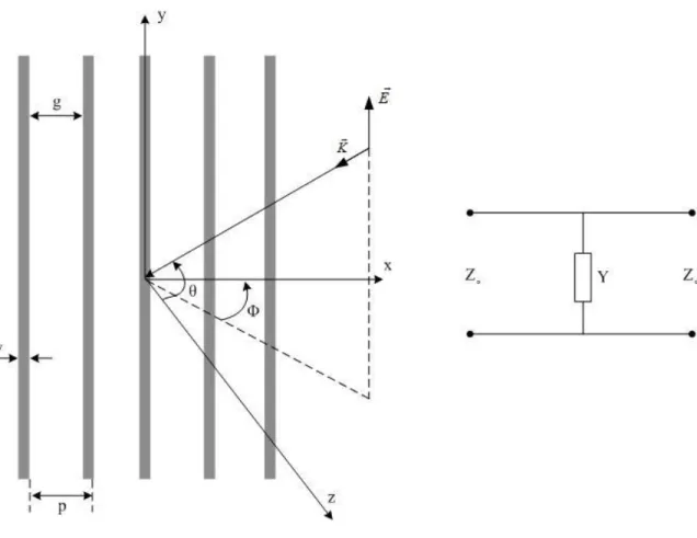
Fig. 3-4 Grating geometry of infinite parallel strips [80]. ... 28
Fig. 3-5 Inductive grid geometry and its equivalent transmission line model. ... 30
Fig. 3-6 Transmission power response of an inductive planar grid and its transmission line model... 35
Fig. 3-7 Schematic representation of passive FSS filters. (a) Square-loop screen [60]. (b) Gridded square-loop screen [59]. ... 38
Fig. 4-1 Passive capacitive grid incorporated with ideal active elements. (a) Geometry of the grid. (b) Typical transmission response of the passive inductive and capacitive grid for normal incident. ... 41
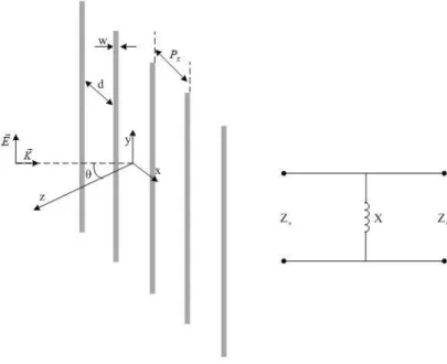
Fig. 4-2 Geometry of inductive FSS screen and its transmission line model. ... 44
Fig. 4-5 Geometry of capacitive FSS screen and its transmission line model. ... 47
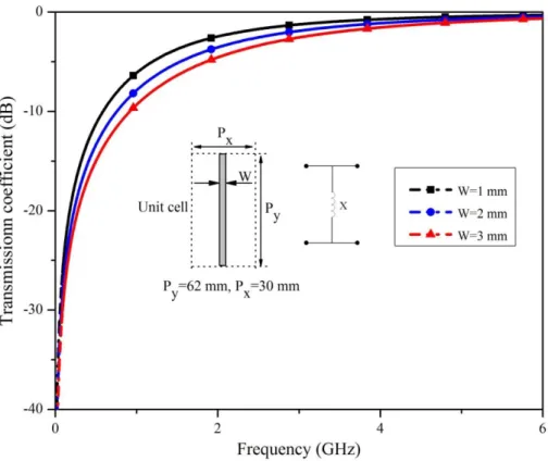
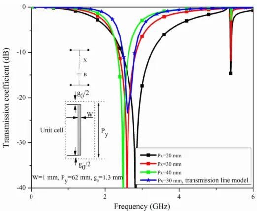
Fig. 4-6 Transmission coefficient response of the screen shown in Fig. 4-5 for various . ... 47
Fig. 4-7 Transmission coefficient response of the screen shown in Fig. 4-5 for various . ... 48
Fig. 4-8 Transmission coefficient response of the screen shown in Fig. 4-5 for various w. ... 48
Fig. 4-9 Transmission coefficient response of the screen shown in Fig. 4-5 for various . ... 49
Fig. 4-10 Effect of ratio on capacitive grid response. ... 50
Fig. 4-11 Effect of supporting dielectric on the grid response. ... 52
Fig. 4-12 Effect of gap width on the grid response... 53
Fig. 4-13 Effect of active element on the grid response. (a) PIN-diode model. (b) Simulated transmission coefficient for different parasitic capacitance values. ... 53
Fig. 4-14 Geometries of two serial-fed reconfiguration mechanisms and their transmission coefficient responses. (a) Vertical fed. (b) Horizontal fed. ... 54
Fig. 4-15 Flat reflector antenna geometry. ... 56
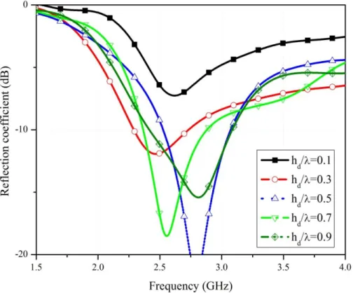
Fig. 4-16 Reflection coefficient of the flat reflector antenna for different values ofh . d (All dimensions are in mm). ... 57
Fig. 4-17 Parametric studies of flat reflector antenna carried out for realized gain at different values of H, L, and . (All dimensions are in mm). ... 58
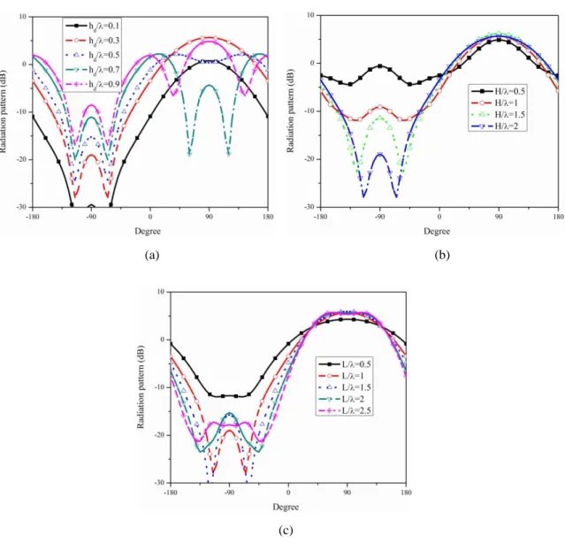
Fig. 4-18 Parametric studies of flat reflector antenna carried out for H-plane radiation-pattern at different values of (a), H (b), and L (c). (All dimensions are in mm). ... 59
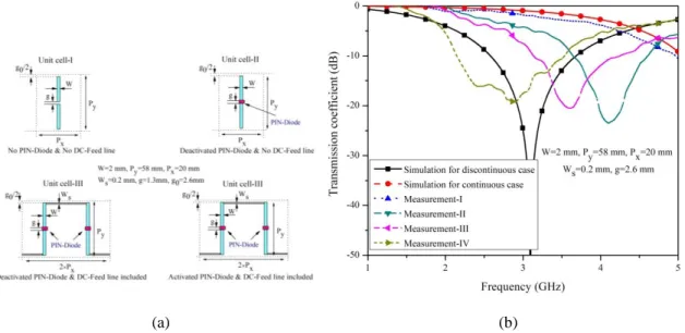
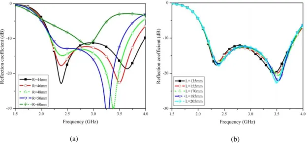
Fig. 4-19 Parametric studies of flat reflector antenna carried out for E-plane radiation-pattern at different values of (a), H (b), and L (c). (All dimensions are in mm). ... 60 Fig. 4-20 Transmission coefficient measurement setup. ... 61 Fig. 4-21 Evaluating the performances of a FSS screen based on the first proposed unit cell. (a) Four different FSS screens constructed using 24×4 elements of these unit cells. (b) Measured transmission coefficient compared to the simulation. ... 62 Fig. 4-22 Photo of fabricated prototype (a), and reflection coefficient results (b). ... 63 Fig. 4-23 Antenna radiation-patterns. (a) E-plane pattern. (b) H-plane pattern. ... 64 Fig. 5-1 Geometry of the proposed active reconfigurable cylindrical frequency selective surface antenna (ARCFSSA). ... 67 Fig. 5-2 Geometry of the semi-cylindrical reflector antenna. ... 68 Fig. 5-3 Geometry of a corner reflector superimposed into a semi-cylindrical reflector antenna. ... 69 Fig. 5-4 Reflection coefficient of semi- cylindrical reflector antenna for different values of R. (a) Results for different values of R. (b) Results for different values of L. ... 71 Fig. 5-5 Realized gain of semi- cylindrical reflector antenna. (a) Results for different values of R. (b) Results for different values of L. ... 71 Fig. 5-6 Radiation-patterns of semi- cylindrical reflector antenna for different values of R and L. (a) H-plane for different R values. (b) H-plane for different L values. (c) E-plane for different R values. (d) E-plane for different L values. ... 72 Fig. 5-7 Cylindrical FSS screen and number of active elements along its length and circumference. ... 73 Fig. 5-8 Reconfigurable cylindrical reflector antenna. (a) Perspective view of the antenna (b) Schematic distributed geometry of FSS screen, . (c) Dipole antenna used in the proposed switched-beam cylindrical reflector antenna
of the unit cell, (all in mm). (b) Amplitude and phase of reflection coefficient. (c) Amplitude and phase of transmission coefficient. ... 75 Fig. 5-10 Parametric study of antenna shown in Fig. 4-7 performed for various R values. (a and b) Reflection coefficient for various R and . (c and d) Gain for various R and . (e and f) Normalized H-plane radiation-pattern for various R and . (g and h) Normalized E-plane radiation-pattern for various R and . ... 77 Fig. 5-11 Comparison of antenna radiation characteristics for the cases with and without parallel DC-feeding lines. (a) Reflection coefficient. (b) Gain. (c) H-plane radiation-pattern. (d) E-plane radiation-radiation-pattern. ... 78 Fig. 5-12 Photo of fabricated switched-beam reconfigurable antenna. ... 79 Fig. 5-13 Measured and simulated results for switched-beam reconfigurable antenna (a) Reflection coefficient. (b) Realized gain. (c) H-plane radiation-pattern. (d) E-plane
radiation-pattern. ... 82 Fig. 5-14 Nimble radiation-pattern antenna. (a) Antenna configuration. (b) Distributed configuration of applied cylindrical FSS screen. ... 84 Fig. 5-15 Simple and modified unit cell configurations FSS screen used in nimble
radiation-pattern antenna. ... 84 Fig. 5-16 Scattering parameters of simple and modified unit cells. (a) Amplitude of transmission coefficient. (b) Phase of transmission coefficient. (c) Amplitude of
reflection coefficient. (d) Phase of reflection coefficient. ... 85 Fig. 5-17 Antenna radiation characteristics performed for various R values. (a) Reflection coefficient. (b) Realized gain. (c) E-plane radiation-pattern. (d) H-plane radiation-pattern. ... 87 Fig. 5-18 Antenna radiation characteristics performed for various values. (a) E-plane radiation-pattern. (b) H-plane radiation-pattern. ... 87 Fig. 5-19 Parametric study performed for different stub length showing its effect on the stop-band performance... 88 Fig. 5-20 Photo of fabricated nimble beam antenna. ... 90
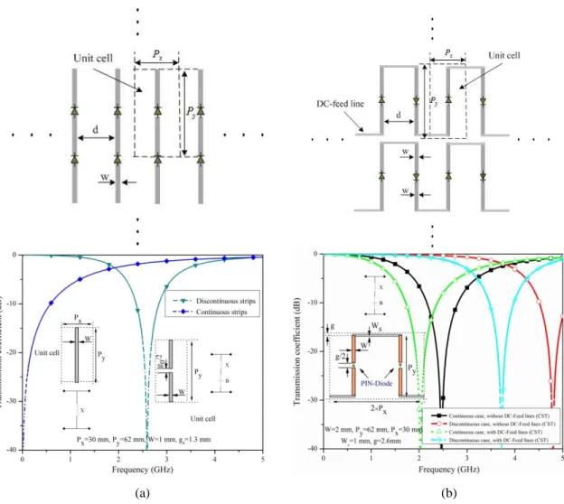
Fig. 5-21 Simulated and measured reflection coefficient for nimble beam antenna. ... 90 Fig. 5-22 Measured pattern for nimble beam antenna (a) H-plane radiation-pattern. (b) E-plane radiation-radiation-pattern. ... 91 Fig. 5-23 Measured and simulated realized gain of nimble antenna. ... 92 Fig. 6-1 Geometry of dual band reconfigurable FSS screen and transmission line model of its unit cell. ... 96 Fig. 6-2 Transmission coefficient response of two basic resonant elements. (a)
Discontinuous strips. (b) Discontinuous elliptical rings. ... 97 Fig. 6-3 Transmission and reflection coefficient response of hybrid dual band
reconfigurable FSS screen (a) Transmission coefficient. (b) Reflection coefficient. ... 97 Fig. 6-4 Transmission coefficients of hybrid unit cell for different unit cell sizes. (a) For different values of . (b) For different values of . (c) For different values of . (All values are in mm). ... 98 Fig. 6-5 Agile frequency nimble radiation-pattern antenna. (a) Antenna geometry. (b) Excitation source. ... 99 Fig. 6-6 Parametric studies on reflection coefficients carried out for the most crucial dimensions. (a) For different values of R. (b) For different values of . (c) For different values of . ... 101 Fig. 6-7 Parametric studies on radiation-patterns carried out for the most crucial
dimensions at 2.45GHz. (a) E-plane for different values of R. (b) E-plane for different values of . (c) E-plane for different values of . (d) H-plane for different values of R. (e) H-plane for different values of . (f) H-plane for different values of . ... 102 Fig. 6-8 Parametric studies on antenna gain carried out for the most crucial dimensions. (a) For different values of R. (b) For different values of . (c) For different values of . ... 103 Fig. 6-9 Measured and simulated transmission coefficients. (a) FSS-A. (b) FSS-B. ... 105 Fig. 6-10 Fabricated prototype of agile nimble radiation-pattern antenna. ... 107 Fig. 6-11 Measured and simulated reflection coefficients of dipole and agile frequency nimble. ... 108
Fig. 6-13 Measured and simulated radiation-pattern of agile frequency nimble antenna in
directional case. (a) H-plane. (b) E-plane. ... 110
Fig. 6-14 Measured and simulated radiation-pattern of dipole and agile frequency nimble antenna in omni-directional case. (a) H-plane. (b) E-plane ... 111
Fig. 8-1 Configuration d’antenne BIE cylindrique. ... 119
Fig. 8-2 Grille capacitive passive intégrée à des éléments actifs. ... 121
Fig. 8-3 Géométrie d’un écran SSF inductif et son model en ligne de transmission. ... 122
Fig. 8-4 Effet de la périodicité de la grille sur le coefficient de transmission. ... 123
Fig. 8-5 Géométrie d’un écran capacitif SSF, son modèle en ligne de transmission, et sa réponse en coefficient de transmission. ... 124
Fig. 8-6 Effet d’un élément actif sur la réponse de la grille (a) Modèle de la diode PIN. (b) coefficient de transmission Simulé pour différentes valeurs de capacités parasites. 125 Fig. 8-7 Géométries de deux mécanismes de reconfiguration d’alimentations séries et leurs réponses en coefficient de transmission. (a) Alimentation verticale. (b) Alimentation horizontale... 127
Fig. 8-8 Géométrie d’une antenne à réflecteur plan. ... 128
Fig. 8-9 Évaluation des performances d'une SSF basé sur la cellule de base proposée. (a) Quatre différents SSF construits en utilisant 24×4 éléments de ces cellules de base. (b) Coefficient de transmission mesuré comparé à la simulation. ... 129
Fig. 8-10 Photo du prototype fabriqué (a), et des résultats du coefficient de réflexion (b). ... 129
Fig. 8-11 Diagramme de rayonnement de l’antenne. (a) Diagramme E plan (b) Diagramme H plan. ... 130
Fig. 8-12 Géométrie de l’antenne SSF active, reconfigurable, cylindrique proposée (ASSFARC). ... 131 Fig. 8-13 Antenne reconfigurable à réflecteur cylindrique. (a) Vue en perspective de l’antenne (b) Schéma de la géométrie distribuée de la SSF .
(c) Antenne dipôle utilisée dans l’antenne à réflecteur cylindrique à faisceau commuté
, (valeurs en mm). ... 132
Fig. 8-14 Photo de l’antenne reconfigurable à faisceau commuté fabriquée. ... 133
Fig. 8-15 Résultats mesurés et simulés pour l’antenne à faisceau reconfigurable commuté (a) Coefficient de réflexion (b) Gain réalisé. (c) Diagramme de rayonnement dans le plan H (d) Diagramme de rayonnement dans le plan E. ... 134
Fig. 8-16 Antenne agile en diagramme de rayonnement (a) Configuration de l’antenne (b) SSF cylindrique appliquée à une configuration distribuée. ... 135
Fig. 8-19 Diagramme de rayonnement mesuré pour antenne à faisceau agile (a) Diagramme de rayonnement dans le plan H. (b) Diagramme de rayonnement dans le plan E. ... 136
Fig. 8-17 Photo de l’antenne agile fabriquée. ... 136
Fig. 8-18 Coefficient de réflexion simulé et mesuré pour antenne à faisceau agile. ... 136
Fig. 8-20 Simulation et mesures du gain réalisé de l’antenne agile... 137
Fig. 8-21 Géométrie d’une SSF double bande reconfigurable et modèle de ligne de transmission de sa cellule de base. ... 139
Fig. 8-22 Réponse des coefficients de transmission et réflexion d’une SSF double bande hybride reconfigurable. (a) Coefficient de transmission. (b) Coefficient de réflexion. .. 140
Fig. 8-23 Antenne agile en diagramme de rayonnement et en fréquence. (a) Géométrie de l’antenne (b) Source d’excitation. ... 141
Fig. 8-24 Coefficients de transmission simulés et mesurés. (a) SSF-A. (b) SSF-B. ... 142
Fig. 8-25 Prototype fabriqué de l’antenne agile en diagramme de rayonnement. ... 143
Fig. 8-26 Coefficients de réflexion simulé et mesuré et gain du dipôle et de l’antenne agile en fréquence. (a) Coefficient de réflexion. (b) Gain. ... 143
Fig. 8-27 Diagramme de rayonnement simulé et mesuré du cas d’une antenne agile en fréquence dans le cas directif. (a) Plan H. (b) Plan E. ... 145
Fig. 8-28 Diagramme de rayonnement simulé et mesuré du cas d’une antenne agile en fréquence dans le cas omnidirectionel. (a) Plan H. (b) Plan E. ... 145
List of Tables
Tab. 2-1 Comparison of different reconfigurable approaches. ... 14
Tab. 3-1 FSS lattice type and grating-lobe criteria [61]. ... 24
Tab. 5-1 Final dimensions of the switched-beam reconfigurable antenna. ... 74
Tab. 5-2 Radiation characteristics of switched-beam antenna. ... 80
Tab. 5-3 Final dimensions of nimble radiation-pattern antenna. ... 88
Tab. 5-4 Radiation characteristics of Nimble antennas compared to semi-cylindrical reflector. ... 92
Tab. 6-1 Final dimensions of the agile nimble beam antenna. ... 101
Tab. 6-2 Final dimensions of the fabricated FSS sheets and agile frequency nimble antenna. ... 104
Tab. 6-3 Antennas characteristics. ... 112
Tab. 8-1 Caractéristiques de rayonnement de l’antenne à faisceau commuté. ... 134
Tab. 8-2 Caractéristiques de rayonnement d’antennes agiles comparés au réflecteur semi-cylindrique. ... 138
Chapter 1
Introduction
1. 1
Motivation
Advanced communication systems have recently received a growing attention because of their abilities to provide various functionalities in an individual unit, introducing less cost, more versatility, robustness, and significant saving in volume and maintenance. For instances, increasing number of cell-phone users, aside of the main purpose of instant vocal accessibility, is interested to benefit other amenities, including multimedia, GPS, and internet [1, 2]. Each of these services operates over different frequency bands, or may need to use polarization/space diversity to improve the quality of the system. These trends show that more and more communications can be performed with a single platform.
Intelligent systems, as another example of modern systems, are on the rise in both industrial or military applications, which are looking for new generation of small, low cost and versatile components to increase the overall system performances as well [3]. Depending on the type of the communication functions, a modern system requires to provide desired actions in the reception modules as well as data processing units. Therefore, because of holding a paramount role in the antenna system embodiments, antenna design and development have attracted a great eminence in the antenna design arena to explore various types of multi-functional configurations. This leads to increase the overall performances of the communication systems by integrating a few functions in a single element and hence not littering the platform by multiple antennas to handle each function.
has received a growing attention to explore new antennas with different operating characteristics, including frequency, polarization, and radiation-pattern (RAs) according to the desired system requirements [4]. On the other hand, RA alleviates detriments of the traditional antennas and mitigates demerits of adaptive or smart antennas leading to increase the overall communication system performances. This indeed is achieved by effectively exploiting the available frequency spectrum and all the antenna-system potentials, which may improve the system efficiency. The extensive applications of agile components in Antennas & Microwave areas and more important the outstanding merits of RAs for modern communication systems have motivated us to establish a comprehensive research in this area. Therefore, this project aims to design, analysis, and fabricate a number of new reconfigurable antennas based on periodic structures for modern tactical communication systems.
1. 2
Problem identification
It is well known that because of their anomalous behavior, periodic structures have widely been applied in microwave and antennas by exploring their desired characteristics. They are designed in different configurations as summarized in [5] in which they are either served to create new materials with unusual electromagnetic properties or treat in a special way with the incident waves. The former is generally recognized as negative materials, while the later can be classified as electromagnetic band-gap materials (EBG) and frequency selective surfaces (FSS). EBG materials are used to create an electromagnetic band-gap response or direct the waves by inserting a defect in the periodic structure. These properties have found interesting applications in antennas to alleviate the surface waves in the planar array configuration [6], increase antenna gain [7-12], and provide efficient low profile antennas by creating high impedance surface (HIS) or artificial magnetic conductor (AMC) as a ground plane [6, 13].
By changing the periodic pattern shape using a certain reconfiguration mechanism, the electromagnetic properties of periodic structures can also be controlled. This concept has been used in antenna domain to control the antennas’ radiation performances in terms of direction of the radiation-pattern or gain [14]. In particular, in [15] a periodic array of metallic rods arranged in a cylindrical shape, as shown in Fig. 1-1, has been utilized to create a directive radiation-pattern. The transmission coefficient response of the periodic structure, analyzed using CST Microwave Studio software in Fig. 1-2, demonstrates that a band-gap is realized by this periodic pattern at low frequencies, prohibiting the propagation of the incident waves through the periodic elements. On the other hand, the inserted angular defect into the periodic pattern directs the electromagnetic waves excited
by the sources at its center. Therefore, a directive radiation-pattern is created by this structure [16].
It is well known that by inserting some discontinuities along the rods, the band-gap response can be eliminated at the desired operating frequency. These discontinuities can be realized by integrating some high frequency PIN-diodes into the structure, offering a reconfigurable band-gap response for the periodic array of rods. Therefore, by using this reconfiguration mechanism, the angular direction of the defect in the periodic pattern is changed. Indeed, this reconfigurable defect provides the feasibility of sweeping entire azimuth angles in a few steps. However, this structure must be implemented in multi-layer configuration, making it complex and difficult in fabrication. Furthermore, a large number of active elements are needed, which increases the cost of the antenna system. The functionalities of the antenna are also limited to sweeping beam and reconfigurable between directional and omni-directional beams.
Therefore, this thesis aims to introduce new antenna configurations based on other periodic structures, i. e., frequency selective surfaces, to reduce the number of used active elements and hence lessen the antenna complexity. Moreover, it is expected to take advantages of the hybrid periodic structures and increases the functionality of the antenna.
1. 3
Problem remedies and project objectives
As a kind of periodic structures, frequency selective surfaces (FSS) have received a particular attention in the microwave and antenna domains. They are usually used to filter out the incident electromagnetic waves over a specific bandwidth or let them pass through the FSS screen. This finds appropriate applications in the reflectors, filters, absorbers, and radomes [17-19]. When the phase of the incident/transmission wave is controlled, the FSS structure can be used to manipulate the antenna beam direction [20], change the polarization of the scattered waves [17], or provide zero phase reflection surfaces [13]. In most of these applications, the FSSs are passive and they cannot electronically or mechanically change their electromagnetic responses.
The benign electromagnetic behavior of FSS screens in respect to the incident electromagnetic (EM) waves has grasped researchers’ attention to benefit them in reconfigurable antennas, as well. In [21-23], a low profile reconfigurable antenna has been addressed in which an active meta-surface has been used as a partially reflecting surface to tune the resonant frequency and enhance the antenna gain. For some other contributions, tunable high impedance surfaces (HIS) or artificial magnetic conductors (AMC) based on the FSS concept have been proposed to steer the antenna
pattern [14, 24, 25]. Reconfigurable FSS textures have also been used to develop some phase shifters as the elements of reflect array antennas to steer the antenna radiation-pattern or as elements of a lens antenna [20, 26, 27].
In this work, a new class of reconfigurable FSS screens is proposed to create a number of reconfigurable antennas, and hence to tackle the disadvantages of the above mentioned EBG-based reconfigurable structure, shown in Fig. 1-1. Indeed, the transmission/reflection responses of each planar FSS are carefully delineated to elaborately reshape the screens to a cylindrical form. The cylindrical shape is deliberately chosen to achieve the desired sweeping beam performances over all azimuth angles. Then, by precisely controlling the active elements integrated into the cylindrical FSS, the radiated field of an RF-source at the center of the cylinder is controlled to achieve the desired functionality.
As specific objectives, the designed antennas must operate at 2.45GHz, to be able to sweep whole azimuth angles over minimum 15% of bandwidth using a directive pattern with more than 10dB realized gain. This feature is demanded in the adaptive or smart antenna systems for space diversity or having a directive radiation-pattern at different angles with a single antenna element. The radiation-pattern is also interested to be reconfigured to the omni-directional pattern case, covering instantaneously all azimuth angles. This feature also can be used in the intelligent systems demanding a gain diversity to enhance the performance of the system by increasing the signal-to-noise ratio. The back-lobe level of the radiation-pattern in the directive case would be expected to be better than 20dB. In the design process, the number of active elements needs to be kept as minimum as possible to decrease the antenna cost and also enhance its radiation performances.
1. 4
Thesis executive summary and accomplishments
Thesis summary
1. 4. 1
In order to tackle the above mentioned objectives, firstly a literature review on the reconfigurable antennas is carried out in Chapter-2 to clearly identify this concept. The possible reconfigurable antenna characteristics are explained and their impacts in improving the overall system performances are explained. The most commonly used reconfiguration methods are also described and compared to each other, and finally the chapter is ended up with some remarks on practical considerations.
Following to the research survey presented in the first chapter, comprehensive studies on periodic structures and in particular frequency selective surfaces are presented in
considerations of FSSs are described. As a kind of frequency selective surfaces, the scattering performances of planar inductive and capacitive girds are theoretically and analytically delineated and their responses to incident TE-waves are described according to their lattice dimensions.
Applications of inductive and capacitive partially reflective/transparent surfaces in reconfigurable antennas are the subject of investigations in Chapter-4. The effect of lattice dimensions on the transitivity/reflectivity performances of the grids are analytically explained by their proposed transmission line models. Moreover, the active element integration effects and impact of DC-biasing feed lines on determining the reconfiguration mechanism in designing planar reconfigurable electromagnetic windows are explained in this part. Then, the performances of these surfaces in reconfigurable flat reflector antennas are experimentally evaluated.
To increase the functionality of the flat reflector antenna, two types of reconfigurable antenna based on principles of cylindrical reflector antennas are presented in Chapter-5. Firstly, the principles of cylindrical reflector antennas are investigated to identify the overall design guidelines of the antenna. Then, two screens introduced in the previous chapter are reformed to a conformal cylindrical shape to construct two reconfigurable antennas. The constraints of DC-feeding line method on both the reconfiguration mechanism and the functionality of the antennas are experimentally explored in this part. Moreover, the limitations of each method because of the undesired effects of DC-feeding lines and non-ideal active elements are identified. Furthermore, in this chapter, a new antenna called “nimble-antenna” is introduced and its practical radiation performances are presented. This antenna is able to both sweep entire azimuth angles and reconfigure its pattern between directional and omni-directional cases.
To improve the nimble antenna performances and its functionality, a new FSS is proposed using a hybrid unit-cell configuration in Chapter-6. The design procedure of this hybrid unit cell is presented and its transmission/reflection response is evaluated for agile frequency nimble antenna applications. The most useful practical results of the fabricated prototypes are presented in this chapter, and the potentials of the applied hybrid FSS in creating single band or agile-frequency dual-band reconfigurable antenna are revealed.
At the end, a summary of this work accomplishment is presented in Chapter-7, and the thesis is closed with some research lights gleaming for new future investigation avenues. A French summary of thesis is also presented in Chapter-8.
List of Publications
1. 4. 2
[1]. M. N. Jazi and T. A. Denidni, “Electronically Sweeping Beam Antenna Using a New Cylindrical Active Frequency Selective Surface,” IEEE Trans. on Ant. and Propag., to be appeared, May 2012.
[2]. M. N. Jazi and T. A. Denidni, “Analytical and Experimental Results of a Novel Rejection-Band Ultra-Wideband Dielectric Resonator Antenna Using Hybrid Techniques,” IEEE on Ant. And Wireless Propag. Lett., Vol. 11, p.p. 492-495, May 2012. [3]. E. Erfani, J. Nourinia, C. Ghobadi, M. N. Jazi, T. A. Denidni, “Integrated UWB/Reconfigurable-Narrowband Antenna for Cognitive Radio System Applications,” IEEE on Ant. and Wireless Propag. Lett., Vol. 11, p.p. 77-80, March 2011.
[4]. M. N. Jazi and T. A. Denidni, “Triple-Band Monopole-Like Radiation-pattern Circular Ring Patch Antenna Using Hybrid Technique,” IEEE Trans. on Ant. and Propag., Vol. 59, No. 10, p.p. 3512-3517, October 2011.
[5]. M. N. Jazi and T. A. Denidni, “Frequency Selective Surfaces and Their Application for Nimble-Radiation-pattern Antennas,” IEEE Trans. on Ant. and Propag., Vol. 58, No. 7, p.p. 2227 - 2237, July 2010.
[6]. T. A. Denidni, Z. Weng and M. N. Jazi, “Z-Shaped Dielectric Resonator Antenna for Ultra-Wideband Applications,” IEEE Trans. on Ant. and Propag., Vol. 58, No. 12, p.p. 4059-4062, September 2010.
[7]. M. N. Jazi and T. A. Denidni, “Agile Radiation-Pattern Antenna Based on Active Cylindrical Frequency Selective Surfaces,” IEEE on Antenna and Wireless Propag. Lett., Vol. 9, p.p. 387-388, April 2010.
[8]. M. N. Jazi, and T. A. Denidni, “Design and Implementation of an Ultra-Wide Band Dielectric Skirt Monopole Antenna,” IEEE on Antenna and Wireless Propag. Lett., Vol.7, p.p. 493 - 496, August 2008.
[9]. M. N. Jazi and T. A. Denidni, “Reconfigurable Schemes of Parallel Metallic Strips for Nimble Antennas,” in IEEE Int. Conf. on Ant. and Propag., Chicago, USA, July 8-14, 2012.
[10]. E. Erfani, M. N. Jazi and T. A. Denidni, “Switchable UWB/Multi-Narrowband Antenna for Cognitive Radio Applications,” in IEEE Int. Conf. on Ant. and Propag., Chicago, USA, July 8-14, 2012.
[11]. M. N. Jazi and T. A. Denidni, “Reconfigurable Dual-Band Frequency Selective Surface Using a New Hybrid Element,” in IEEE Int. Conf. on Ant. and Propag., Washington State, USA, July 1-7, 2011.
Band Rejection,” in IEEE Int. Conf. on Ant. and Propag., Toronto, Canada, July 11-17, 2010.
[13]. M. A. Habib, M. N. Jazi, A. Djaiz, M. Nedil, M. C. E. Yagoub and T. A. Denidni, “On IP3 Performance Investigation in Reconfigurable Active EBG Antenna,” in IEEE Int. Conf. on Ant. and Propag., Toronto, Canada, July 11-17, 2010.
[14]. M. N. Jazi, T. A. Denidni and Adel R. Sebak, “Ultra-Wideband Dielectric-Resonator Antenna Based on Hybrid Techniques,” in Int. Symp. on ANTEM/AMEREM, Ottawa, Canada, July 5-9, 2010.
[15]. M. N. Jazi and T. A. Denidni, “Design and Implementation of an Ultra-Wide Band Dielectric Resonator Antenna for Communication Systems,” in the 18th Iranian Conf. on Elec. Eng., Isfahan, Iran, May 11-13, 2010.
[16]. M. N. Jazi, M. A. Habib and T. A. Denidni, “Electronically Switching Radiation-pattern Antenna Using an Active Cylindrical Frequency Selective Surface,” in IEEE Int. Conf. on Ant. and Propag., Charleston, USA, July 1-5, 2009.
[17]. M. N. Jazi, M. A. Habib and T. A. Denidni, “Reconfigurable Radiation-Pattern Antenna Based on Active Frequency Selective Surfaces,” in IEEE Int. Conf. on Ant. and Propag., Charleston, USA, July 1-5, 2009.
[18]. M. A. Habib, M. N. Jazi, A. Djaiz, M. Nedil and T. A. Denidni, “Switched-Beam Antenna Based on EBG Periodic Structures,” in Int. Microwave Symp. (IMS), Boston, USA, 2009.
[19]. M. N. Jazi and T. A. Denidni “A New Hybrid Skirt Monopole Dielectric Resonator Antenna,” in IEEE Int. Conf. on Ant. and Propag., San Diego, USA, July 5-12, 2008. [20]. M. N. Jazi, and T. A. Denidni, “Design and Implementation of an Ultra-Wide Band Dielectric Resonator Antenna for Electronic Warfare (EW) Systems,” in the second Int. Conf. on Wireless Communications in Underground and Confined Areas (ICWCUCA), p.p. 107-109, Canada, August 25-27, 2008.
Chapter 2
Reconfigurable antennas
2. 1
Introduction
Demands on low cost, high quality, robust and high data rate communication systems, capable of adapting to the unpredictable or/and harsh electromagnetic environments, have proliferated some attractive emerging research topics so called electronically controlled, smart-adaptive, and agile-reconfigurable antennas [1, 2, 4, 28, 29]. Certainly, all these research areas have been conducted, more or less in a common reason, to ameliorate the restrictions of commonly used antennas. Indeed, the conventional antenna in intelligence systems, for instance planar phased-array technology, restricts both scan angles and operation because of the limitations of individual array elements and antenna element spacing. On the other hand, smart-adaptive antennas refer to a bunch of antennas positioned in a special configuration to be weighted by a particular terminology for a precise scenario, improving the overall performances of the communication system. In this way, the antenna system is able to adapt their radiation characteristics to the new required operating requirements in a harsh EM environment. In particular, by applying the concept of beam-forming method, the radiation intensity of the antenna system can be focused in a desired direction, leading to eliminate undesired signals. This actually entails a higher S/N ratio at the receivers and saves the battery power at the transmitters. However, smart-adaptive antenna systems require a complex and complicated adaptive feed network and also a controlling system to weight each antenna element according to the desired beam-forming scenario [1, 2, 30]. Moreover, there is no any smartness in the antenna elements, limiting the overall performances of the communication system.
detriments of the conventional antennas as well as demerits of the smart or adaptive antenna systems [4]. By applying reconfiguration mechanism in a single antenna element, different tasks can be handled by only one antenna in a communication system, leading to reduce the antenna complexity, cost, and improve the overall system performances. Moreover, introducing some smartness in the antenna elements of adaptive phased-array can significantly increase the versatility of the smart antenna array.
Therefore, this chapter aims to address the reconfiguration concept and its feasible methods. In addition, the typical reconfiguration mechanisms used in some agile antennas are also introduced and compared together in terms of different technical standpoints. Finally, a few reconfigurable structures in antenna and microwave applications are briefly introduced to demonstrate their myriad applications.
2. 2
Reconfigurable antennas
The term of reconfigurable antenna is referred to any radiation structure in which either one or some of its fundamental operating characteristics are controlled by means of electrical or mechanical approaches. Indeed, the key principle in designing these antennas are based on the theory of conventional antennas, and by tailoring the radiator structure, controlling the current distribution, or changing the electrical parameters of the antenna, their desired radiation characteristics are tuned.
Reconfigurable antennas are able to independently alter their operating frequency, bandwidth, polarization, and radiation-pattern to accommodate changing operating requirements. For instance, the ability to tune the frequency could be utilized to change the operating band, filter out the interfering signals, or tune the antenna to account for the new environments [31]. On the other hand, the polarization of the antenna can be reconfigured to separate or distinguish desired signals and hence forming a space filter for the unwanted signals [32-34]. In addition, radiation-pattern reconfiguration can also be used as a space filtering or effectively send the signals to a desired direction [35, 36]. This increases the sensitivity of the receiver or the maximum transmitting range of the system.
Changing more than one property of the antenna at the same time is another feature that is highly demanded in the modern communication systems [4, 30, 37]. However, the reconfiguration on one property, for instance frequency, has direct consequence on the radiation-pattern. Likewise, reconfiguration that results in radiation-pattern will also alter the frequency response of antennas. This linkage is one of the largest challenges faced by reconfigurable antenna developers who would usually prefer the characteristics to be separable. This research topic is called “compound reconfigurable antennas” which can
also be classified as multi-functional antennas. Although, some structures have been proposed to implement compound antennas, individually controlling each property without affecting the others is a holy grail. In the following sub-sections, three fundamental reconfigurable properties of antennas are described in more details.
Frequency reconfiguration
2. 2. 1
In the modern communication systems, different operating bands are required to perform the relevant tasks. Therefore, in except of using one antenna for each task, a dynamic frequency antenna can be applied to carry out all functions. This also reduces the system cost and may increase its overall performances. A reconfigurable frequency antenna is the only candidate that can be used to meet the system requirements. In these antennas, since the antenna size relative to the wavelength is kept constant, almost the same characteristics are obtained by changing the frequency.
The frequency reconfiguration can be performed continuously or by means of switch. Both methods are based on a unique key principle─ that is changing the effective electrical length of the radiator or, on the other hands, the effective current distribution on the radiator. By using continuous variation, the frequency of the antenna can be reconfigured smoothly over a specific bandwidth; while, for discontinuous cases, reconfiguration is realized by switching between different bands. The main difference between these two methods is the means that are used to change the effective electrical length or current distribution of the antenna. Electrical or mechanical switch including optical switches, PIN-Diodes, FETs, and radio-frequency micro-machined (RF-MEMS) switches are some kind of methods classified as discontinuous frequency reconfigurable approaches. Mechanically changing the antenna structure and material properties are other approaches, which can continuously change the frequency of the antenna. However, each method has its own advantages and drawbacks that according to their potentials for the desired application are chosen.
Polarization reconfiguration
2. 2. 2
Polarization reconfiguration potentially is able to introduce immunity to the interfering signals in the unpredictable environments as well as creating an additional degree of freedom to enhance link quality by means of antenna diversity. Basically, the direction of the current distribution on the antenna dictates the polarization of the radiated electric fields in the far zone regions. Therefore, the polarization reconfiguration is realized by managing the direction of the current distribution usually by changing the antenna structure, material properties, and/or feed configuration. However, it is important to
pattern and matching. This is because by changing the polarization, other antenna radiation characteristics may significantly change. This is the main consideration point in designing this type of reconfiguration property. Although, the key principle of polarization diversity is similar to the one of frequency diversity, the available reported research shows that the switching methods are the most popular approach for polarization reconfigurations.
Radiation-pattern-gain reconfiguration
2. 2. 3
Radiation-pattern/gain reconfiguration is another interesting topic in the reconfigurable antennas, which is usually used as space filtering for increasing the link quality by effectively focusing the radiated signals to the desired direction. This can be achieved even by changing the amplitude and phase of the electric or magnetic currents on the structure. However, because of changing in the current distribution, it is expected to have some variation in the frequency response of the antenna as well. This is the main technical point that should be considered in the design process to minimize the effect of pattern/gain reconfiguration on the frequency response and hence matching bandwidth.
Depending on the antenna structure, frequency of operation, and fabrication technology, different types of tunable approaches have been proposed for pattern/gain reconfiguration. For instance, structural changing by means of electrical or mechanical actuators is one of approaches in changing the radiation-pattern shape. As an electrical method, MEMS switches have been applied into the antenna structure to change the current distribution and therefore its radiation-pattern [38, 39]. Similar to the frequency reconfiguration, controlling material properties is another method that has been suggested to manage the radiation-pattern. However, applying this method, especially using ferromagnetic materials, introduces the main constraints of losses, higher cross polarization, being bulk and needing a particular biasing structure [40-42]. Using parasitic elements around the primary antenna is another approach, which has been proposed to change the direction of the radiation-pattern. This method possesses attractive qualities, including isolation from the driven element, potentially wide frequency bandwidth, and a range of available topologies and functionalities [43, 44]. In one other approach, the pattern reconfiguration can be achieved by an array of tunable elements in which phase of each element can be adjusted to focus the radiated energy in a particular direction [45]. As it can be deduced, in all radiation-pattern reconfiguration mechanism, by tailoring the antenna structure to different shapes or by changing the electrical parameters of the antenna structural embodiment, the radiation-pattern is reconfigured. In the next sub-section, some of the commonly used reconfiguration mechanisms have been described.
2. 3
Reconfiguration methods
The study on the reconfiguration properties shows that the reconfiguration mechanisms are usually achieved by means of mechanical or electrical approaches [4]. In the mechanical method, the structure of the radiator is moved by electromechanical actuators in order to reshape the antenna structure. Piezo-electric actuators or micro-machined plastic deformation are some kinds of recently proposed methods to reconfigure the frequency and radiation-pattern. This method delivers a wide range of frequency of operation limited by the practical constraints and it can continuously sweep the desired property through a bandwidth or switch between different regimes. In addition, it provides low loss, linear behavior at high frequencies, which are remarkable merits to alleviate the inter-modulation (IMD) harmonic problem. However, needing to a specific complex actuation system and being low speed are the main drawbacks of this approach.
On the other hand, in the electrical methods there is no any movement in the configuration and the changes in the overall shape is electronically achieved. Indeed, this is realized by connecting/disconnecting different parts of the structure, changing the elements of the equivalent electrical circuit model of the antenna via variable capacitors or by changing the material properties. Optical switches, high frequency PIN-Diodes, FETs, and radio frequency micro-mechanical switches (MEMS) are some kinds of commonly used means applied to connect or disconnect different parts of the antenna. These components are applicable to reconfigure frequency, polarization, or radiation-pattern. Inter-modulation (IMD) harmonic level, losses, and speed are the main important issues for these approaches, which determine the component type for the desired operating requirements. Among these drawbacks, the undesired natural parasitic elements introduced by component packaging and soldering, for instance in PIN-Diodes and FETs, are the main reasons in limiting their applications. This leads to increase the elements nonlinearity and hence increase the IMD problem. MEMS technology is the potential approach to get rid of the losses and parasitic elements by packing the reconfiguration mechanism and antenna structure during the fabrication process. However, this method is not practical for all applications and is not extensively available in the market.
Alternatively, variable capacitors are other components that are usually used to continuously reconfigure the frequency response of the antenna over a specific bandwidth. This can be realized by chip variable capacitors integrated into the structure. These capacitors are usually based on the semiconductor or MEM technologies. However, because of packaging parasitic elements and losses, the application of these components is limited, especially for the components based on the semiconductor technologies.
Technology Tuning range
Power
consumption Bias Speed IMD
Semi-conductors
Schottky (GaAs) HBV( GaAs) Abrupt p-n junction (Si)
PIN-Diode High <1 mW <1 mW <5 mW <0.1 mW <5 V <20 V <30 V <10 V <1 ns <5 ns <10 ns <1 μs Poor Poor Poor Poor Magnetic YIG (Variable permeability ferromagnetic resonance) Remnant magnetization Magneto-static (spin) wave - - - High Low Low Current (Coil) Current (Coil) - <5 ms <5 ms <5 ms - - - Ferroelectric Thin film Thick film Bulk Moderate to high Moderate to high Moderate to high Negligible Negligible Negligible <30 V <1000 V <15 KV <1 ns <10 ns <1 μs Low Low Low Liquid
crystal Cavity/Bulk Moderate Negligible <40 V <10 ms - Optical Photoconductivity - <10 mW Current (LD,
LED)
10 fs-10
ms -
Mechanical MEM Varactor
Piezo-transducer Low High Negligible Negligible <50 V >100 V >10 μs >100 μs Excellent Good
Changing the material properties is another interesting method, which mainly is applied to reconfigure the radiation-pattern and frequency response [46-48]. Liquid crystals (LC), ferroelectric and ferromagnetic materials are some kind of these materials, which have been utilized as means of reconfiguration. In these methods, by applying a DC voltage or magnetic field, the electrical properties of the dielectrics are changed, leading to alter the EM response of the structure. Ferromagnetic materials and LCs are bulkier than ferroelectric materials and they create more losses than ferroelectrics. Moreover, creating higher cross polarization level in ferromagnetic is other reason to not widely apply these materials directly as radiators in the antenna applications.
In summary, the above mentioned reconfiguration approaches have been compared in different technical standpoints in Tab. 2-1. Based on the data listed in this table, it can be conclude that implementing the reconfiguration structure by means of MEM technology proposes better performances in terms of loss, speed, power consumption, and more important IMD level. It can be observed form this table that ferroelectric materials may ranks as the second approaches to implement a high speed, low loss reconfigurable structure with low IMD level. However, the practical limitations, operating frequencies,
and technology constraints restrict the designer to choose a specific reconfiguration mechanism for the desired applications.
2. 4
Reconfigurable antennas and their practical
issues
The technical advantages offered by tunable/reconfigurable antennas have introduced them as potential candidates for multi-function or smart communication systems. Therefore, they have found a myriad of applications in different areas including satellite communications, base stations, wireless sensors, and medical areas. Moreover, by growing different technologies to develop agile materials, for instance, high frequency semi-conductor switches and capacitors, micro electromechanical systems (MEMS) [49], ferroelectric materials [40, 41], liquid crystals [50], and most recently plasma materials [51], they are getting more interest for the future modern communication systems.
However, there are still some practical issues that may limit or pose some constraint on the applications of these antennas. In many cases, the selected antenna topology and intended applications restrict the choice of reconfiguration mechanism and some trade-offs need to be considered. Those trade-trade-offs may include, reconfiguration speed, power consumption, actuation requirements (voltage or current), fabrication complexity, durability, device lifetime, complexity of control and bias networks, weight, size, cost, dynamic range, sensitivity, and, of course, overall performance of antenna system.
Once the reconfiguration mechanism is selected, the integration of reconfiguration mechanism inside the radiator element is one of the most challenging issues in developing reconfigurable antennas. Indeed, the required controlling network for the selected relevant reconfiguration mechanism must be comprehensively considered in the design process. For instance, if RF-MEMS or PIN-diode switches are selected as reconfiguration method, the required biasing network and also any non-ideal effect must be included in the design. Moreover, sometimes by reconfiguring one characteristic, the antenna matching is deviated. This demands a matching circuit that is required to be integrated into the antenna structure.
The above mentioned difficulties are usually faced in the design steps. Reviewing reported research reveals that reconfigurable antennas have been under development in the past a few decades; however, not all of them put in to the operation in the today systems. Indeed, there are some other technical points that need to be considered for the future design to effectively take advantages of them in the practice.
The first issue is the benefits and costs of the reconfigurable antenna in the system point of views. Although, there are a handful of reported quantitative studies in which the system-level performance of these antennas has been considered [4], still more work
eventually, a particular reconfigurable antenna with clear features can address known limitations or predicted operating scenarios. Moreover, to fully take advantages of multi-functionality feature and select the best antenna configuration, collaborative efforts are demanded between the designers in the hardware and software levels.
In terms of the cost and complexity, sometimes introducing the reconfiguration into the system significantly increases the complexity and cost of the system. This is because some more controlling units which are required to collect and process the received data, and then select the new system requirements according to the new operating scenario. Therefore, budgetary constraints may simply preclude inclusion of a reconfigurable antenna in a system. To make reconfigurable antennas more affordable in the future systems, some advances can be introduced in the fabrication and system implementation. For instance, directly integrating the switch elements and associated control lines during the design and implementation process would result in more economical configuration. In summary, still more work both in hardware and software is demanded to effectively bring these antennas in the current practical smart systems.
2. 5
Conclusion
The research survey on the topic of reconfigurable antenna demonstrates that still this topic is in the developing period and more multi-disciplinary research considering both hardware and software level of the antenna system is demanded. Integrating reconfiguration mechanism into the antenna structure is one of the challenging topics in this area to alleviate or eliminate the undesired effect of the applied reconfiguration mechanism. Serving new technologies to propose more versatile reconfigurable structures is another attractive research area in this topic. Furthermore, introducing a smart element as components of an adaptive array antenna can also be an ultimate challenging configuration for the future modern smart communication systems.
Chapter 3
Periodic structures and their applications in
antennas and microwave
3. 1
Introduction
In the past two decades, an interesting area, broadly named as Meta-materials, has increasingly attracted researcher attention to develop and improve performance of electrical components in RF, microwave, and high frequency bands [5]. Depending on the way that they treat with the incident electromagnetic waves, these materials can be realized as Double Negative (DNG) materials, Electromagnetic Bandgap structures (EBG) or Photonic Bandgap materials (PBG), and Frequency Selective Surfaces (FSS). They are constructed of an array of periodic elements arranged in one, two or three dimensional pattern. Each element of these arrays can be metallic, dielectric or a composite material of metal and dielectric. The element shape, array texture, electrical parameters of material, and the distance between elements in the array dictate their electromagnetic properties. All these materials might treat in distinct ways to the waves with different incident angles or polarizations. Therefore, their performances for vertical and horizontal polarization at various incident angles are the subject of investigation depending on the desired application.
For instance, DNG materials in response to the incident electromagnetic waves provide negative dielectric constant and dielectric permeability. The periodicity of the array elements in these types of periodic structures (PS) is much smaller than the operating wavelength. DNG materials have received considerable attention in developing scanning
have been addressed in [52] that the readers are referred. Alternatively, PBG or EBG materials are another type of meta-materials that prohibit the propagation of incident waves across a range of frequency band. The periodicity of the array in these materials is in the range of a half wavelength. They have found intense applications in antennas to enhance the gain or suppress the surface waves as high impedance ground surface (HIS) or artificial magnetic conductors (AMC) [5, 6], in microwave filters to create band stop responses [53, 54], and in electromagnetic shielding applications [55]. Recent contributions on the application of these materials in antennas and microwave have been described in [56].
Finally, the subject of interest in this thesis, i. e. FSS surfaces, is a kind of planar periodic arrays of metallic patches or perforated conductors with a particular pattern. Depending on their impact on either one or both of amplitude and phase of the incident waves, they have found considerable applications in antennas, filters, polarizers, radomes, and electromagnetic shieling [17-19]. Moreover, by cascading some layers of these surfaces, FSS-based EBG configurations have also been developed for antenna applications [57]. In this perspective, comprehensive research studies have been carried out during past a few decades to theoretically and experimentally investigate the performances of these surfaces in one or cascaded multi-layer configurations. The element types, lattice geometry selection, supporting dielectrics’ effect, incident angles and polarizations sensitivity, and reconfiguration feasibility have been individually examined to design robust FSS electromagnetic windows [17]. To perform these investigations, different theoretical approaches based on electromagnetic full wave solutions have been developed to calculate the FSS response. A comprehensive research survey on these methods has been summarized in [58].
On the other hand, as more easier method with less tedious computer calculations, an equivalent transmission line model is an alternative approach to predict the transmission/reflection performance of these surfaces [59, 60]. Although, this method has been developed for a certain regular element and lattice shapes for a limited range of incident angles, it easily provides the initial values of the FSS dimensions and describes the physical scattering mechanism of the surfaces.
Since the objectives of this thesis are proposing and developing a new class of sweeping-beam reconfigurable radiation-pattern antennas based on periodic structures (PS), the relevant reported contributions on this particular application are reviewed and discussed in this chapter. In this perspective, as a type of periodic structures, FSS screens are described and their electromagnetic characteristics are explained. Typical elements used in FSS textures are classified and the FSS design considerations are identified. Then, some of the most important applications of FSS surfaces are addressed. Finally, as basic principles used in this thesis to design a class of FSS-based reconfigurable
antennas, the fundamentals of capacitive and inductive FSS screens constructed by gridded array of strips are theoretically and analytically explored.
3. 2
Frequency selective surfaces
Frequency selective surfaces (FSSs) are referred to a two-dimensional infinite array of metal patches or an array of aperture in a metal sheet [17]. Since FSS surfaces have originally been developed as spectral filters, sometimes those can be recognized as dichroic surfaces as well [19]. The first FSS prototype as a partially reflector surface has been reported in 1919 by Marconi and Franklin. However, because of the highly demanded interest in military, intense theoretical and experimental investigations have been embarked on this subject in the mid-1960s.
FSSs are fundamentally characterized by their responses to the incident electromagnetic (EM) waves. Indeed, these screens will transmit nearly all EM waves over a specific bandwidth while reflecting nearly all energy through another frequency bandwidth. A single layer FSS screen is generally constructing by aperture or patch elements. Free space standing aperture and patch elements provide a complementary response [17]. The electromagnetic fields are totally transmitted by a resonant aperture, while an FSS screen constructed by an array of resonant patches blocks the propagation of EM waves. The phase of transmitted or reflected waves can also be altered by the screen. This helps to eliminate a specific electric field component of the EM waves passing though the screen or change the polarization of the reflected or transmitted waves. Depending on the system requirements of a design, the frequency response may be tailored to be narrow or wide, to have multiple pass or stop-bands, or to be polarization dependent. Elements spacing, element shape and dielectric parameters are the key factors, dictating the frequency response of the screen. FSS lattice can also be considered as a design parameters to attain particular performances, for instance, packing the elements to mitigate the incident angle dependency of the EM response of FSS screens and therefore alleviate the grating lobe responses. Consequently, this is the desired application and system requirements that dictate the FSS design parameters. The range of these applications extends across the electromagnetic spectrum, from the microwave to infrared where screens are fabricated with micromachining capabilities [61]. In the following sections, the design parameters of FSSs are identified and some of the basic applications of these antennas are introduced.