UNIVERSITÉ DE SHERBROOKE
Faculté de génie
Département de génie mécanique
MODÉLISATION DE L’ÉTANCHÉITÉ DU MOTEUR X-MINI DE
LIQUIDPISTON
MODELING THE SEALING OF THE X-MINI ENGINE BY
LIQUIDPISTON
Mémoire de maîtrise
Spécialité : génie mécanique
Maxime LEBOEUF
Sherbrooke (Québec) Canada
Septembre 2019
JURY MEMBERS
Mathieu PICARD
Supervisor
Jean-Sébastien PLANTE
Examiner
François CHARRON
Examiner
i
RÉSUMÉ
Les moteurs rotatifs sont utiles pour les applications qui demandent une grande densité de puissance. Ces moteurs ont, par contre, souvent des fuites importantes de la chambre de combustion, de l’usure prématurée des joints d’étanchéité et une grande consommation d’huile. Les moteurs rotatifs de la famille X de la compagnie LiquidPiston utilisent une géométrie différente des moteurs de type Wankel traditionnels et l’un de leurs prototypes, le X-Mini, a le potentiel de réduire les fuites des moteurs rotatifs en éliminant les mécanismes de fuites les plus importants. Cependant, étant un type de moteur très récent, très peu d’études furent conduites au sujet des performances de scellement du moteur. Ce projet vise à quantifier les performances de scellement du moteur X-Mini. Un modèle des joints d’étanchéité est développé et utilisé afin d’estimer les fuites du moteur. Le modèle s’avère capable de relier la dynamique des joints d’étanchéité aux fuites de gaz, en permettant ainsi d’identifier et de quantifier l’importance relative de chacun des mécanismes de fuites du moteur. Il inclut les forces de pression des gaz, les forces hydrodynamiques créées par les couches d’huiles sur les parois, les forces des ressorts en place, les pseudo-forces reliées à la rotation du rotor et les forces de contact avec les autres parois. Le modèle utilise des éléments courbes pour modéliser le joint de face et une technique de double discrétisation afin d’obtenir des résultats adéquats tout en gardant le temps de résolution bas. Chaque fonction utilisée pour le calcul des forces fut validée en comparant avec une solution analytique. Le modèle d’éléments finis fut validé en comparant la solution numérique avec une solution analytique pour poutres courbes ainsi qu’avec la solution donnée par un logiciel commercial d’éléments finis.
Selon les résultats du modèle, le moteur en question possède en effet une aire de fuite équivalente 65% plus petite qu’un moteur Wankel de taille similaire, en considérant une fuite par aire de scellement constante. Ces résultats sont supportés par des tests expérimentaux sur dynamomètre qui montrent des fuites 35% moins grandes en comparaison au même moteur Wankel. Ces résultats positionnent le moteur de LiquidPiston à mi-chemin entre les moteurs à piston et les moteurs de type Wankel en termes de performance de scellement.
ii
ABSTRACT
Rotary engines are useful for applications that require high power density. However, these engines often show significant leakage from the combustion chamber, premature wear of the seals and high oil consumption. LiquidPiston's X-Engine family of engines use a different geometry than traditional Wankel-type motors and one of their prototypes, the X-Mini, could reduce rotary engine leakage by eliminating significant leakage mechanisms. Being a new type of engine, very few studies have been conducted on this engine sealing performance.
This project focuses on quantifying the combustion chamber leaks of the X-Mini engine. A model of the seals is developed and used to estimate engine leakage. The model is able to link seal dynamics to gas leaks, allowing the identification and quantification of each of the engine's leak mechanisms. It includes the gas pressure forces, the hydrodynamic forces created by the oil layers on the walls, the spring forces, the pseudo forces associated with the rotation of the rotor and the contact forces. The model uses curved elements to model the face seal and a dual-grid discretization technique to obtain precise results while keeping the computational time low. Each function used to calculate the forces was validated by comparing with an analytical solution. The finite element model was validated by comparing the numerical solution with an analytical solution for the deformation of curved beams, and with a numerical solution given by a commercial finite element software. According to the model, this engine has a 65% smaller leakage area than a Wankel engine of similar size, while dynamometer testing shows a 35% smaller leakage area. These results bring the engine approximatively midway between the piston and Wankel engines in terms of sealing performance.
iii
TABLE OF CONTENTS
RÉSUMÉ ... i ABSTRACT ... ii 1 INTRODUCTION ... 1 1.1 Context ... 1 1.2 Research Question ... 3 1.3 Objectives ... 3 1.4 Contributions ... 3 1.5 Document Plan ... 42 STATE OF THE ART ... 5
2.1 Piston Engines ... 5
2.2 Wankel Engines ... 8
2.3 X-Engine architecture ... 10
3 X-MINI SEALING PERFORMANCES ... 12
3.1 Abstract ... 14
3.2 Introduction ... 14
3.3 X Engine Sealing System ... 18
3.3.1 Face Seals ... 18
3.3.2 Apex Seals ... 19
3.4 Analytical Development ... 21
3.4.1 Apex Seal Model ... 21
3.4.2 Face Seal Model ... 26
3.5 Modeling Results ... 32
3.5.1 Apex Seal Model Results ... 32
3.5.2 Face Seal Model Results ... 33
3.6 Experimental Results ... 34
3.7 Equivalent Leakage Area ... 35
3.8 Summary/Conclusions ... 38
4 CONCLUSION ... 39
5 CONCLUSION ... 40
iv
LIST OF FIGURES
Figure 1 : X-Mini engine from LiquidPiston ... 2
Figure 2: Rotary engine geometry of the a) Wankel engine and the b) X-Engine ... 2
Figure 3 : Power cylinder system of piston engines [6] ... 6
Figure 4: The presence of a ring gap is essential to allow the seal to deform ... 7
Figure 5 : Measured blowby for one cylinder of an automobile spark-ignition engine[7] ... 7
Figure 6 : The apex, side and oil seals control the gas and oil flow in the Wankel engine [14] ... 9
Figure 7 : At 8000 rpm, leakage is relatively equally distributed between the 3 types of seals[19]. ... 10
Figure 8 : The cooling and intake flow enter the engine axially and a mix of exhaust gases and cooling flow exits on the other side. ... 16
Figure 9 : The X engine 4 steps of a power stroke a) Intake b) Compression c) Combustion d) Exhaust ... 17
Figure 10 : The X engine features 3 stationary apex seals and 2 face seals ... 18
Figure 11 : The face seal running face and flank surfaces prevent leakage between the high pressure chamber and the side of the rotor ... 19
Figure 12 : The apex seals a) are located on the intersection of each working chamber b) are preventing the gas to flow from one chamber to the other ... 19
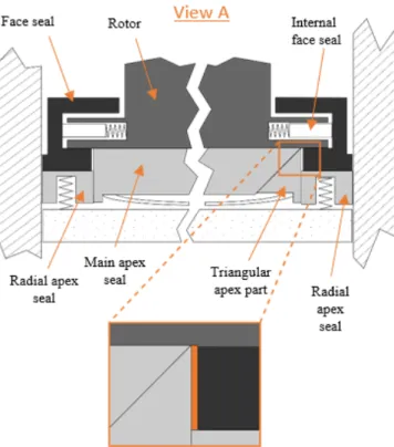
Figure 13 : The apex seal 4 pieces design goal is to keep the geometrical leakage to a minimum (View A from Figure 12 is depicted) ... 20
Figure 14: Running face and flanks leakage ... 20
Figure 15 : The forces included in the apex seal model are: a) contact, friction, and spring forces and b) gas forces ... 22
Figure 16: Pressure distribution in the channels is approximated by a Poiseuille flow... 24
Figure 17 : Three degrees of freedom are included in the apex seal model: lateral displacement, radial displacement and tilt ... 25
Figure 18: Dual-grid discretization of the face seals ... 27
Figure 19 : The face seal can move in 4 different ways – circumferentially (𝑥), radially (𝑦), and axially (𝑧) – and tilt (𝛽) ... 27
Figure 20: Deformed element in the y direction ... 29
Figure 21 : Forces acting on the face seal cross-section a) Contact, spring and friction forces b) Gas and pseudo forces ... 31
Figure 22 : The leakage caused by the dynamics of the apex is small compared to the geometric leakage as the pressure difference is small when the apex moves from one flank to the other and remains in contact with the low pressure flank when the chamber pressure is high ... 32
Figure 23 : Position of the seal and chamber pressures at a) start of cycle b) TDC of chamber 3 c) expansion of chamber 3 d) compression of chamber 2 e) TDC of chamber 2 f) end of cycle ... 33
v
Figure 24 : Model results show that the face seal conforms to the rotor in the high pressure zone, but lifts off in the low pressure zone. Gas pressure is illustrated in black, contact pressure is illustrated in red and blue represents the inertial forces ... 34 Figure 25 : The face seal a) leaks on a good portion of the cycle, but at a relatively
controlled rate b) leak mass flow is influenced by the pressure in each chamber ... 34 Figure 26 : The x engine equivalent leakage area was calculated by comparing GT-Power results and experimental data [20] ... 35 Figure 27 : The X engine eliminates some of the most important leakage mechanisms of the Wankel by its design... 37
1
1
INTRODUCTION
1.1
Context
Internal combustion engines are used almost everywhere in society. Almost all cars, trucks, tractors, genset and power equipment are powered by them. Fuel tanks allow to easily stock chemical energy, which gives them an edge in autonomy and portability. For consumer applications like road vehicles and handheld devices, most of the internal combustion engines use a piston architecture to transfer this chemical energy in motion.
Power density is an important parameter in today’s society, which is always looking for lighter, but more powerful devices. The Wankel rotary engine is an engine design that possesses a higher power density than typical piston engines. Both have very different geometries. Wankel engines rely on an orbiting rotor rather than pistons to transfer the energy from the fuel to the crankshaft.
The Renesis engine from Mazda is an example of the Wankel family of engines. This 1.3 liter engine can produce around 230 horsepower without forced induction methods, which made it popular in performance cars.
However, this type of engine still has major issues, notably a high fuel and oil consumption, important wear of the seals and trouble meeting emissions standards. A portion of these problems are therefore linked to the sealing-related problems [1]. In fact, the Wankel engine seals are known to underperform the piston engines’ seals as they have to seal a significantly more complex geometry. These reasons can explain why the production of the Renesis engine stopped in 2011. However, Wankel engines are still manufactured as part of the UAV market, thanks to their high power density [2, 3].
New engine concepts are now being developed to exploit the high-power density of the rotary engine geometries while avoiding the drawbacks typically associated with them. The X-Mini is an example of these new rotary engine concepts. It is currently being developed by LiquidPiston, a startup company based in Connecticut, United States, and uses the
X-2
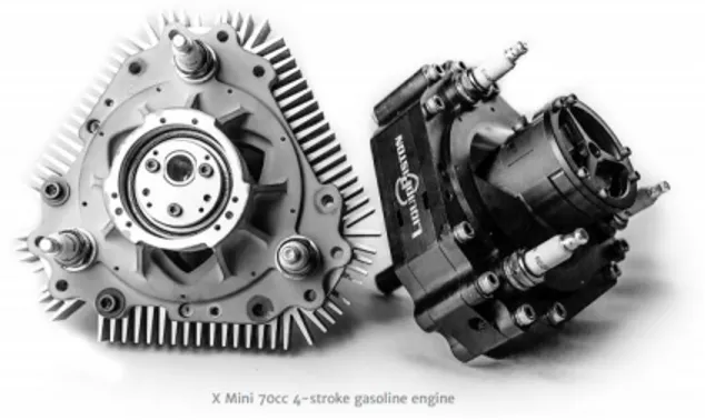
Engine architecture, proprietary of the same company. The X-Mini engine is presented in Figure 1.
Figure 1 : X-Mini engine from LiquidPiston
As opposed to the Wankel engine, this engine is based on the High Efficiency Hybrid Cycle (HEHC) [4]. This cycle is a high pressure ratio Atkinson cycle, which allows the gas to expand more than it is compressed and translates in an efficiency gain [5]. Figure 2 shows the difference in geometry between a Wankel engine and the X-Engine family of engines.
Figure 2: Rotary engine geometry of the a) Wankel engine and the b) X-Engine
The X-Mini engine can be represented as a Wankel engine turned inside-out. The Wankel engine has a triangle shaped rotor rotating in an oval shaped housing, while the X-Mini has an oval shaped rotor rotating in a triangle shaped housing.
This geometry change results in a better combustion efficiency because of the difference in shape of the combustion chambers. The combustion chamber of the X-Mini has a more
3
circular and compact shape than the long and thin combustion chamber of the Wankel engine. This design results in better combustion and less heat losses. It also allows the apex seals of the engine to be static in the housing instead of moving with the rotor, eliminating the dynamic effects caused by their rotation with the rotor. This geometry also eliminates the need for the apex seals to run over the spark plug holes, which was creating a leak path between adjacent chambers in the Wankel engine.
The X-Mini possess a unique sealing geometry that allows it to significantly improve sealing performances compared to rival Wankel engine. However, as the X-Mini is the only engine of its kind, there is no existing model to predict the sealing performances. It is in this optic that the current project started.
1.2
Research Question
LiquidPiston’s engine being a promising new engine, the current research project will try to answer the following research question:
Can the X-Mini engine by LiquidPiston improve the gas sealing performance compared to that of the Wankel rotary engines, and if so, by how much?
1.3
Objectives
The main objective of the project is to quantify the equivalent leakage area of the X-Mini engine and to classify its repartition in different leakage mechanisms. The repartition of the leakage mechanisms can also be compared with the Wankel engine. A secondary objective is to deliver to LiquidPiston the models developed, so that they can be used as a design tools for upcoming generation of engines.
1.4
Contributions
The work done on this project brought the following scientific contributions;
A model to analyze the sealing properties of an engine using the X-Engine architecture;
A first evaluation of the sealing properties of the X-Mini engine;
A better understanding of how LiquidPiston’s geometry reduces gas leakage compared to the Wankel rotary engine;
4
A comparison of the equivalent leakage area given by the model and by experiments.
1.5
Document Plan
The following document first presents how the leakage performances of piston, rotary and X-engines are modeled. The following section then presents a published peer-review conference paper describing the X-Mini engine from LiquidPiston, the model used to evaluate the sealing performances, and the findings of the model.
5
2
STATE OF THE ART
Reducing leakage flow is a constant objective in combustion engines. Through the years, engineers have looked for ways to decrease the amount of pressure loss due to leakage. This led to estimation methods for the leaks, experimental measurements, and complete models of the seals. The following study focused on the techniques used to predict the leakage area of internal combustion engines, more specifically the piston engine, the Wankel engine and the X-Engine from LiquidPiston.
2.1
Piston Engines
Piston engines have been studied for several decades and have been the subject of countless studies. Car manufacturers have dedicated impressive resources for the development of increasingly efficient engines since the invention of the automobile in 1885.
One of the major parameters affecting the efficiency of an engine is the performance of its seals. Without performant seals, gas will exit the combustion chamber and will result in power losses and, in spark-ignition engines, increased unburned hydrocarbon emissions.
In a piston engine, the combustion chamber is connected to various volumes known as crevices. Examples of crevice volumes include the space between the piston rings, the space between the piston rings and the piston, the thread around the spark plug, and the head gasket cutout to name a few. During the compression stroke, the pressure increase in the combustion chamber, and gas flows in these volumes. Some gas then flows from these crevices to the crankcase. This flow is called blowby. The remaining gas flows back to the combustion chamber when the pressure decreases.
Both crevices flow and blowby have a negative impact on power and efficiency of the engine. In this work, leakage is defined as the blowby flow of the engine, or in other words, the amount of gas that flows past the seals.
Blowby flow is sometimes quantified in volumetric or mass flow units. At other times, it is quantified as the total blowby gas weight per cycle. Another method to quantify this flow
6
is through the use of an equivalent leakage area. The leakage area is the area of a virtual constant-area orifice in the combustion chamber which would produce the same amount of leakage when compared to the total blowby. This method gives a physical idea of the performance of the seals, and is easier to visualize.
A pack of 2 or 3 different piston rings commonly seals piston engines and prevent blowby flow. The piston geometry allows each ring to have its own dedicated function, as shown in Figure 3. The high pressure of the combustion chamber presses the top ring, or compression ring, against the piston and the cylinder wall, therefore sealing the combustion chamber. The bottom ring, or oil control ring, regulates the oil layer on the cylinder wall to insure sufficient lubrication. The second ring, or scraper ring, is used to scrape the oil and acts as a backup to both the compression and oil control rings.
Figure 3 : Power cylinder system of piston engines [6]
Heywood [7] suggests that the major source of leakage in piston engines is the ring gap located on the piston rings, as illustrated in Figure 4.
7
Figure 4: The presence of a ring gap is essential to allow the seal to deform
Because the ring gap stays relatively constant through the cycle, it can be directly converted into leakage area. As shown in Figure 5, the ring gap typically represents a leakage area between 0.1 to 0.4 mm2 per cylinder for an automobile spark-ignition engine. Scaled to a 4
cylinders car engine, this would translate into a leakage area of 0.4 to 1.6 mm2.
Figure 5 : Measured blowby for one cylinder of an automobile spark-ignition engine[7]
Tian [8] developed models to study the dynamics and torsion of the piston engine seals. His work was able to relate the dynamics of seals, their deformation, as well as the gas flow around them, and therefore the leaks.
Straight beam models [9, 10] have been used to model the piston rings. However, these models require a significant amount of elements to correctly model the seal’s curved
8
geometry and contact with the liner. This high number of elements results in a high computation time.
To address this limitation, Baelden [6] proposed a multi-scale curved beam finite element model of a piston ring seal to study the behavior of seals of conventional piston engines. This model simulates sealing and friction performances in the piston. A particularity of this model is that it uses two levels of discretization in order to obtain precise results by using fewer elements. The first step consists in discretizing the seal in a relatively small number of curved beam elements. Given their curved nature, a lower number of elements is needed to approximate the seal’s deformation. However, because the contact reaction forces are very localized and dependent on the position of the seal, many points are needed to evaluate the correct contact forces distribution on the seal. For this reason, a secondary grid is used to evaluate the forces acting on each element. The combination of both grids therefore allows to get fast and accurate results.
2.2
Wankel Engines
Since the invention of the Wankel engine in the 1950s, several studies have been carried out on the improvement and performance of this type of engine. Large companies have been interested in this engine over the years, including NASA [11], John Deere [12] and, of course, Mazda, whose sports brand history is linked to this type of engine, the most recent of their creation being the Renesis engine. Yamamoto [13] offers a description of the operating principles of rotary engines, useful for understanding the specific aspects of this type of engine.
As opposed to the piston engines, where the cross-section of the seals can be designed independently from the geometry of the engine, the shape of the Wankel seals are dictated by the engine’s geometry. Instead of having 3 seals located on a piston, the Wankel engine has gas seals located on each of the rotor’s edge in addition to the oil seals located around its center bore, as shown by Figure 6.
9
Figure 6 : The apex, side and oil seals control the gas and oil flow in the Wankel engine [14]
Most of the Wankel engine models evaluate the sealing performance by using the equivalent leakage area approach. It was used, by example, by Eberle and Klomp [15], who determined the area of the equivalent orifice of a rotary engine with a performance model, linking the effect of gas losses to engine performance. Their model concluded the equivalent leakage area is 2 mm2 per rotor. Their method links the equivalent leakage area
to the engine’s performance, but not to the dynamics of the seals, which does not allow to understand the relative importance of every leakage mechanism.
The dynamics of the seals were modeled by Matsuura [16, 17], Knoll [18] and others, who were able to predict reaction forces and friction acting on the seals, but their models did not take into account fluid mechanics effects on the seal.
With Picard's research [14, 19], the dynamics of the Mazda engine seals are coupled to engine leakage. The seals are modeled as deformable beams and their behavior is coupled to the fluid flows around them. The side seals are modeled according to the same type of model but using curved beam theory. The model also includes the corner seals, which do not appear in the configuration chosen by LiquidPiston.
This model allows to dress a picture of the repartition of the different leakage mechanisms in the engine, as shown in Figure 7. According to this model, the total leakage per rotor ranges from 1.5 mm2 at low speed to 2 mm2 at high speed, which corresponds to Eberle
10
and Klomp’s predictions. At high speeds, the three major leak sources of the Wankel engine are therefore identified as the corner seals, the spark plugs holes and the side seal flanks. Due to its seal geometry, the X-engine does not have a corner seal, and the spark plug position does not contribute to the blowby flow in the engine. These 2 reasons can help it achieve better sealing performances by eliminating 2 of the 3 worst leakage paths.
Figure 7 : At 8000 rpm, leakage is relatively equally distributed between the 3 types of seals[19].
Picard uses the type of model to study the oil control seals of a rotary engine. The deformation of the joints, which try to conform to the surface on which they move, through a cycle is calculated. This deformation makes it possible to follow, with the use of a control volume approach, the displacement of the oil throughout a cycle. According to the results of this study, the lack of conformability of oil control seals would be the main cause of oil leakage between the sump and the inside of the engine.
2.3
X-Engine architecture
The equivalent leakage area can be measured experimentally by using a model of engine performances and iterating the leakage values until the experimental data fits the model. This approach has been used by LiquidPiston to determine the performance of the engine's sealing system [20]. According to previously published papers by LiquidPiston, the leakage area of a 750cc engine using the X-Engine architecture would be between 0.5 and 1.5 mm2
[21].
If we use Heywood’s [7] estimation of the ring gap presented in Figure 5 to estimate the sealing performance of a 4 cylinders engine, we obtain an equivalent leakage area of 0.4 to
11
1.6 mm2. To be comparable to a common 4 cylinders automotive engine in terms of
displacement, the X-Engine would probably need two 750 cc rotors, bringing it to 1.5 L, and would therefore show an equivalent leakage area of 1 to 3 mm2, therefore leaking
approximatively twice as much as a piston engine, while still showing an improvement over the Wankel Engine, at between 3 and 4 mm2 of leakage area for a 1.3 L engine.
The equivalent leakage area value considered for the 70cc engine studied in this project is 0.8 mm2. However, there is no model that predicts leakage of the X-engine, and the
12
3
X-MINI SEALING PERFORMANCES
Preface
Auteurs et affiliation :
- Maxime Leboeuf : Master’s student, Université de Sherbrooke, Mechanical Engineering Department
- Jean-François Dufault : Ph. D. student, Université de Sherbrooke, Mechanical Engineering Department
- Mark Nickerson : engineer, LiquidPiston Inc. - Kyle Becker : engineer, LiquidPiston Inc.
- Alexander Kopache : engineer, LiquidPiston Inc. - Nikolay Shkolnik : co-founder, LiquidPiston Inc. - Alexander Shkolnik : co-founder, LiquidPiston Inc.
- Mathieu Picard : professor, Université de Sherbrooke, Mechanical Engineering Department
Approval date : January 23th 2018
Publication state : Final manuscript published Publication : SAE Technical Paper
Reference : [22]
French title : Performance d’un système à faible fuites pour moteur rotatif à haute
efficacité
Contribution to the document : This paper contributes to the document by describing the
models used to study the dynamics of both types of seals in the X engine. It also compares the leakage values given by these models to those found in the literature for Wankel engines. It finally presents and compare the analytical results to experimental results.
French summary : Les moteurs rotatifs sont utiles pour les applications qui demandent une
grande densité de puissance. Ces moteurs sont, par contre, souvent associés avec des fuites importantes de la chambre de combustion, de l’usure prématurée des joints d’étanchéité et une grande consommation d’huile. Les moteurs rotatifs de la famille X de la compagnie LiquidPiston utilisent une géométrie différente des moteurs de type Wankel traditionnels et l’un de leurs prototypes, le X-Mini, prétend parvenir à réduire les fuites des moteurs rotatifs en éliminant les mécanismes de fuites les plus importants. Cependant, étant un type de moteur très récent, très peu d’études furent conduites au sujet des performances de scellement du moteur.
Ce projet visait à quantifier les performances de scellement du moteur X-Mini. Un modèle des joints d’étanchéité a été créé et utilisé afin d’estimer les fuites du moteur. Selon les
13
résultats du modèle, le moteur en question possèderait en effet une aire de fuite équivalente 65% moins grande qu’un moteur Wankel de taille similaire, en considérant une fuite par aire de scellement constante. Afin de valider ces résultats, des tests expérimentaux sur dynamomètre furent conduits. Les résultats montrèrent des fuites 35% moins grandes en comparaison au même moteur Wankel. Les deux résultats semblent donc indiquer de bonnes performances de scellement, qui sont, par contre, encore inférieures à celles des moteurs à piston conventionnels. Le modèle créé pourra être complexifié dans le futur afin de raffiner les prédictions de fuites.
14
SAE Technical Paper 2018-01-0372, 2018
Performance of a Low-Blowby Sealing System for a High
Efficiency Rotary Engine
Maxime Leboeuf, Jean-François Dufault, Mark Nickerson, Kyle Becker, Alexander Kopache, Nikolay Shkolnik, Alexander Shkolnik, Mathieu Picard
3.1
Abstract
The X engine is a non-Wankel rotary engine that allies high power density and high efficiency by running a high-pressure Atkinson cycle at high speeds. The X engine overcomes the gas leakage issue of the Wankel engine by using two axially-loaded face seals that directly interface with three stationary radially-loaded apex seals per rotor. The direct-interfacing of the apex and face seals eliminates the need for corner seals of the typical Wankel engine, significantly reducing rotary engine blowby. This paper demonstrates the sealing performance that can be achieved by this new type of seal configuration for a rotary engine based on dynamics models and experiments. The dynamics models calculate the displacement and deformation of the face and apex seals for every crank angle using a time implicit solver. The gas leakage is then calculated from the position of the seals and pressure in the chambers and integrated over a rotor revolution. An “effective leakage orifice” area can be determined, to compare blowby between different engine types. Model results show that the X engine equivalent leakage area could be around 35% that of the leakage area of a similarly sized Wankel engine obtained from the same modeling method, which brings the X engine leakage closer to the piston engine’s leakage range. Initial experimental results support the findings from the model, as the X engine shows an equivalent leakage area of about 65% that of a scaled Wankel engine. This result demonstrates the potential of the X engine to achieve gas sealing improvements through additional seal development.
3.2
Introduction
For applications that need a high-power density, the rotary engine has been an interesting candidate since its debut in the 1950s. In addition to its impressive power density, it also features fewer moving parts and lower vibrations levels compared to piston engines. However, it has seen a decrease in popularity in recent years, notably in the automotive
15
industry, with the last remaining Wankel engine powered car being manufactured in 2012. The withdrawal of rotary engines from the automotive market can be explained by the traditional drawbacks of rotary engines, along with increasing emission regulations around the globe.
An important drawback of the rotary engines is the difficulty to seal the combustion chamber. The Wankel engine’s geometry requires radially loaded apex seals as well as axially loaded face seals, and the interface between these is not effectively sealed which leads to increased leakage. Various scientific work has been done on the Wankel type rotary engines since the 1950’s. The sealing performance of the Wankel engine was studied both experimentally and by modeling. Different methods were used to simulate the Wankel engine by the past, such as commercial softwares [23], CFD tools [24] or analytical calculations [14, 19]. Throughout the literature, the seal leakage values are usually quantified as an equivalent orifice area, which is not directly linked to the dynamics of the seals. This leakage area is usually determined by fitting a full engine cycle simulation model to experimental in-cylinder pressure and other data, tuning parameters such as compression ratio, port flow coefficients, heat transfer multipliers, and leakage orifice areas. For a Mazda Wankel, Eberle and Klomp [15] determined a leakage area value of 2 mm2 per cell, while others [25–27] found 1 mm2.
In an effort to better understand the behavior of the Wankel seals, models were created to study the dynamics of the seals [16–18, 28]. The seal model by Picard [14, 19] successfully relates the sealing performance to the dynamics and deformation of the seals to predict leakage. The final results of the model predict an equivalent leakage area varying between 1 mm2 and 2 mm2 for the Renesis engine. The main conclusion of these studies is
that the seals tend to leak near the extremities of the parts that interact with each other. In a piston engine, since the rings only have a single gap, they are able to achieve better sealing performances than Wankel engines.
The X Engine is a rotary engine with an alternative architecture that has the potential to solve the rotary engine sealing issue by eliminating the need for corner seals. The X engine uses a single face seal each on the front and back rotor periphery. By decreasing the number of interfaces between seals, gaps and potential leakage mechanisms are
16
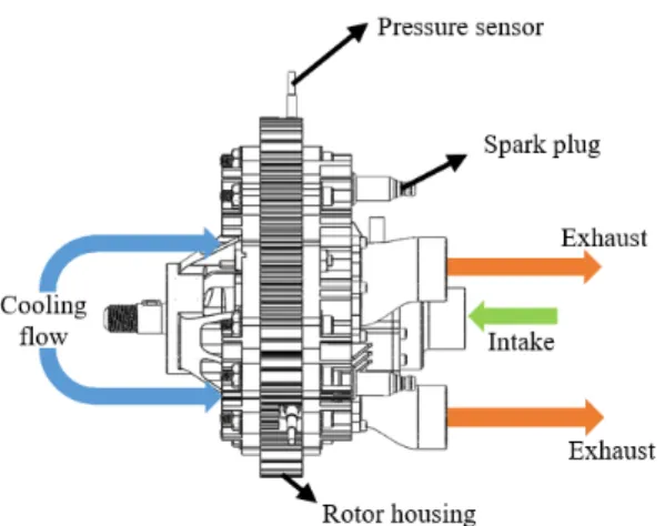
minimized, which benefits the sealing performance of the engine. The X engine is often described as an “inverted” Wankel engine. Its main particularities are the incorporation of constant volume combustion and over-expansion. A 70 cc version of this engine was manufactured and tested on a dyno and in representative environments [29]. In this 70 cc version, depicted on Figure 8, the intake air comes in through the crankshaft and flows through the rotor to fill each of the three working chambers. As the rotor turns, the intake cavity crosses the apex seals, which opens a flow path between the crankshaft and each working chamber. As the rotation of the rotor continues, the intake port then crosses the apex seal on the other side of the working chamber, which closes the intake air flow path. The gas in the working chamber is then compressed, ignited, and expanded until the exhaust port reaches an apex seal and allows the gases to escape the combustion chamber into the exhaust duct. The main steps of a power stroke are presented in Figure 9.
Figure 8 : The cooling and intake flow enter the engine axially and a mix of exhaust gases and cooling flow exits on the other side.
17
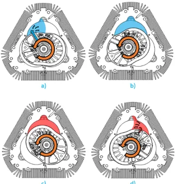
Figure 9 : The X engine 4 steps of a power stroke a) Intake b) Compression c) Combustion d) Exhaust
As the X engine is relatively new, a limited quantity of information has been published on the X engine sealing system. The current literature describes the general architecture of the engine [30, 31], the development of the engine [29] to achieve a working prototype and heat transfer losses predictions and measurements [32]. No previous work on the X engine shows a seal model with the level of details of the ones used for the Wankel or the piston engines.
This paper presents the sealing system of the X engine and an evaluation of its performance. Modeling techniques for the Wankel engine are used to determine the dynamics, deformation, and ultimately the leakage of the seals. Each of the different leakage paths of the working chamber is identified, explained and quantified in order to obtain a final equivalent leakage area value, which is then compared to a scaled Wankel engine. Modeling results show that the X engine’s sealing strategy decreases the equivalent leakage area by approximately 65% as compared to a similar sized Wankel engine. The model results are supported by experimental data which shows leakage values of 35% less than the same sized Wankel engine for an engine with less development invested compared to the Wankel engine.
18
3.3
X Engine Sealing System
The X Engine relies on pressure actuated seals shown in Figure 10 to prevent blowby in the three working chambers. Three apex seals are used between the chambers and two face seals are used at the interface between the rotor and the housing plates. The absence of corner seals reduces the number of gaps to seal compared to Wankel engines and therefore tends to increase the sealing performance.
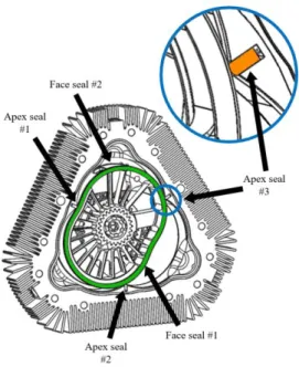
Figure 10 : The X engine features 3 stationary apex seals and 2 face seals
3.3.1
Face Seals
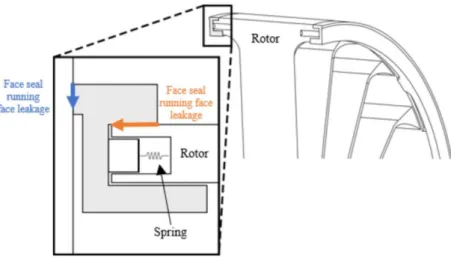
The face seals are located on each side of the rotor and are constituted of two parts, the internal and external face seals. The internal seal is pre-loaded by springs located inside the rotor. It then transfers the spring load uniformly on the external face seal. The external face seal is the key component in the assembly. Mounted on the exterior of the rotor, it prevents high pressure gases in the working chamber from leaking to the atmosphere through its flank and through the running face, as shown on Figure 12. The face seal is activated by the pressure in the working chamber and conforms to both the housing and the rotor, sealing the gaps and preventing pressure losses.
19
Figure 11 : The face seal running face and flank surfaces prevent leakage between the high pressure chamber and the side of the rotor
3.3.2
Apex Seals
The apex seals show a design similar to Wankel apex seals, but are stationary on the housing instead of moving with the rotor. The apex seal tips therefore run on both the rotor and face seal surfaces. By making them stationary, the seals are not subjected to centrifugal forces, which makes them more stable in the groove. Gaps and seal dimensions are very close to the Wankel engine apex seals. Figure 12 and Figure 13 show the X engine apex seal components.
Figure 12 : The apex seals a) are located on the intersection of each working chamber b) are preventing the gas to flow from one chamber to the other
20
Figure 13 : The apex seal 4 pieces design goal is to keep the geometrical leakage to a minimum (View A from Figure 12 is depicted)
Figure 14: Running face and flanks leakage
The apex seals are composed of 4 different parts. The two pieces located at the extremities of the apex seal are called radial pieces. The radial pieces are running on the face seals in order to adjust to the relative motion between the face seals and the rotor. The two
21
remaining pieces are very alike to the Wankel apex seals. The purpose of this 4-parts design is to minimize geometrical leakage by limiting gaps between parts. The four pieces of the apex seal are spring-loaded to ensure constant contact with the running surface and are activated by the working chamber pressure.
The three possible leakage paths associated with the apex seals are geometrical leakage, running face leakage and flanks leakage. In Figure 13, the geometrical leakage area is showed. It is defined as the gap between the apex seal parts, which is caused by thermal and mechanical deformations as well as manufacturing tolerances of the parts. Figure 14 illustrates the running face and flanks leakage mechanisms. Leakage between the rotor and the running face of the apex happens when the forces on the apex are not balanced and the seal separates from the rotor. The leakage between the groove and the apex side happens when the apex seal moves from one side of the groove to the other under the action of pressure variations, creating a path for the gas located under the apex to flow towards a lower pressure chamber.
3.4
Analytical Development
In order to quantify the leakage performance of the X Engine, two models are developed, one used for the apex and the other one for the face seals. The models are based on the modeling strategies previously used by Picard [14, 19] to model the Wankel engine. Both models showed minimal leakage caused by the movement of the X engine seals. The remaining leakage paths are located at the interfaces between the parts.
3.4.1
Apex Seal Model
The X Engine apex seal performance can be evaluated by studying the displacement of the seal in its groove during a complete cycle. To do so, a model solving the rigid-body displacements of the seal for every crank angle is used. The apex seal model aims to quantify two different types of leakage, the flank leakage flow and the running face leakage flow. The flanks leakage is due to the apex moving from one side of the groove to the other and the running face leakage occurs if the apex seal loses contact with the rotor, or if the apex does not conform completely to the rotor due to thermal and mechanical deformations. The position of the rotor and pressure in each chamber for each time step are inputs to the model, as they are known based on experimental data.
22 3.4.1.1 Forces on the Apex Seal
Figure 15 represents the apex seal in its groove and a free-body diagram shows the different forces acting on the seal which are considered in the model. The principal types of forces that have been considered are the gas forces, the spring forces, the contact reaction forces and friction. Gas forces are caused by the gas pressure acting on each face the seal. Spring forces are the result of the spring load on the seal. Contact forces are caused by reaction forces when the seal is in contact with the groove. Friction forces are proportional to the contact forces and opposed to the relative motion between the parts. Simplified analytical models are used to calculate all the forces, which are then summed in the lateral and radial directions of the seal and reported back to the centroid to evaluate tilt moments.
Figure 15 : The forces included in the apex seal model are: a) contact, friction, and spring forces and b) gas forces
3.4.1.2 Contact sub-model
The asperity contact pressure is calculated as a function of the clearance between the seal and the groove, noted as h. The contact sub-model uses a simplified Greenwood-Tripp relation [33]. 𝑃𝑐𝑜𝑛𝑡𝑎𝑐𝑡 = { 0 𝑓𝑜𝑟 ℎ 𝜎⁄ 𝑝 ≥ 𝑧 𝑃𝑐(𝑧 − ℎ 𝜎𝑝) 𝐾𝑐 𝑓𝑜𝑟 ℎ 𝜎⁄ 𝑝 < 𝑧 3.1
23
The Pc, z and Kc constants are taken from piston engine work by Chen [34] to represent the topography of the groove. They are respectively equal to 127 kPa, 4.8 and 6.804. The σp
parameter represents the standard surface roughness deviation. It is set at 0.1 µm based on surface roughness measurements. Using these parameters guarantees that the penetration of the seal into the groove is physically possible and therefore acceptable.
Friction between the rotor and the apex seal is calculated using the contact pressure and a friction coefficient of 0.15.
3.4.1.3 Gas Pressure & Leakage Flow
The gas pressure in each chamber is measured experimentally and the resulting pressure traces are used to calculate the pressure on both side of the apex at each time step. The pressure is measured near the center of the combustion center, but is estimated to be the same in all the working chamber.
Because the gas in the flank channels move at a much greater speed than the apex itself, the gas flow in the channels is approximated as a Poiseuille flow. The gas flow q is calculated by integrating the cubic height of the channel:
𝑞 = − Δ𝑃
12𝜇 ∫𝐿𝑐ℎ13𝑑𝑥𝑐
0
3.2 in which Δ𝑃 is the pressure difference at both ends of the channels, calculated using the pressure traces for the combustion chambers and the variable which represents the mass of gas under the apex seal, 𝜇 is the dynamic viscosity of the fluid, h is the height of the channel, 𝑥𝑐 is the distance in the direction of the channel and 𝐿𝑐 is the total length of the
24
Figure 16: Pressure distribution in the channels is approximated by a Poiseuille flow
Knowing the fluid flow across the entire channel, the pressure distribution can be identified by using the previous relation to identify the pressure variation throughout the channel:
𝑑𝑃 =12𝜇𝑞𝑑𝑥𝑐
ℎ3 3.3
The gas flow is considered incompressible to calculate the pressure distribution acting on the seal, but the mass flow is limited by the maximum compressible flow allowed through an orifice with an area equivalent to the minimum section of the channel.
3.4.1.4 Oil Film Pressure Generation
The hydrodynamic pressure generated by the oil film can be implemented in the model. However, based on results from the model including hydrodynamic pressure, it has little impact on the leakage values and it thus not included in this paper for the sake of simplicity. It should be noted that hydrodynamic pressure must be included to correctly predict friction power and wear.
25 3.4.1.5 Solver
For every crank angle step, the model uses a Newton-Raphson iterative algorithm that minimizes an error function to find an acceptable value for every variable comprised in the unknown vector 𝑋𝑎: {𝑋𝑎} = { 𝑥𝑎 𝑦𝑎 𝜙𝑎 𝑚𝑔 } 3.4
in which xa and ya are the displacement of the center of mass of the apex in the direction
of the groove and perpendicular to the groove, 𝜙 a is the angle of the center of mass of the
seal and mg is the fluid mass in the volume under the apex. The subscript a refers to the
apex seal reference frame. All these variables are shown at Figure 17. The mass of fluid under the apex is an unknown because it depends from and affects the flow in and out of the cavity. By using the volume of this cavity, it is possible to calculate the pressure under the apex, and therefore the flow in both channels on the flanks of the apex, as explained in the gas pressure and leakage flow section. The pressure in this cavity also impacts the forces distribution acting on the apex seal.
Figure 17 : Three degrees of freedom are included in the apex seal model: lateral displacement, radial displacement and tilt
26 {𝐺} = { 𝐹𝑥− 𝑚 ∙ 𝑎𝑥 𝐹𝑦 − 𝑚 ∙ 𝑎𝑦 𝑇𝜙− 𝐼 ∙ 𝛼𝜙 𝑚𝑔̇ − Δ𝑚𝑔 Δ𝑡 } 3.5
in which 𝐹𝑥 and 𝐹𝑦 are the forces acting on the seal in the direction x and y, 𝑇𝜙 is the
moment applied to the seal, 𝑎𝑥 and 𝑎𝑦 are the acceleration of the seal in the x and y
direction, I is the moment of inertia, 𝛼𝜙 is the angular acceleration of the seal, 𝑚𝑔̇ is the
time derivative of the mass of gas under the seal, Δ𝑚𝑔 is the total mass flow rate into and
from the groove and Δt is the time step used.
If the residuals are below an acceptable tolerance, the model moves to the next time step, if not, the solver continues to iterate. This tolerance is chosen to ensure it is small enough to represent the physics accurately, but big enough to allow the model to converge in a reasonable time.
3.4.2
Face Seal Model
The face seal model shares a lot of similarities with the apex seal model. The same Newton-Raphson solver is used in both models. The asperity contact function used is still based on the simplified Greenwood-Tripp relation, and the flow equations are still based on a Poiseuille flow. However, the face seal is much more flexible than the apex seal, and it would lead to false conclusions to evaluate it as a rigid body. It is therefore studied as a flexible beam.
To adequately identify the leakage flows around the seal, its deformation must be known for all time steps. To calculate the deformation of the seal, a dual-grid finite elements approach inspired by Baelden [6] is used. The face seal is therefore split in a specified number of curved beam elements, each having their own radius of curvature and length. The radius of curvature of each element is constant throughout the element, and is calculated by using an average of the radius of curvature of the element. The number of elements must therefore be high enough to correctly represent the shape of the face seal.
A second grid is then used to discretize each element into even smaller elements, which will be used to calculate forces. This second grid allows to have a good resolution on the forces distribution, while keeping the number of degrees of freedom relatively low,
27
therefore allowing the model to run smoothly. Both grid are illustrated in Figure 18, where Le represents the length of each element, θe is the angular length of the element and F
represents the forces applied on each of the contact points on the second grid.
Figure 18: Dual-grid discretization of the face seals
In this model, the seal can deform in 4 different ways, which are presented at Figure 19. The circumferential and radial deformations are linked together, as one will impact the other. Axial deformation and tilt are also linked.
Figure 19 : The face seal can move in 4 different ways – circumferentially (𝑥), radially (𝑦), and axially (𝑧) – and tilt (𝛽)
The face seal is not a closed ring, as it possesses a gap similar to piston ring’s gaps, and is not restrained circumferentially, which supports the neglecting of the warping effects.
28
Because the cross-section dimensions of the seal are an order of magnitude less than the radius of curvature of the elements, the curved beams elements are treated as thin beams. The effects of shear forces on the deflection of the seal are negligible compared to bending effects. The displacements are small, as the seal is constrained by the rotor.
For every time step, the deformation of the nodes in the first grid and their derivatives are used to estimate the deformation of the seal in each of the contact points, or points on the second grid. Forces are then calculated and integrated on these contact points. The forces and deformation and then iterated until they satisfy equilibrium.
3.4.2.1 Rigidity and mass matrices
The face seal model considers the seal as flexible, as opposed to the apex seal which was considered rigid. The rigidity term (K) is therefore added to the error function:
{𝐺} = {𝐹} − [𝐾]{𝑋} − [𝑀]{𝑋̈} 3.6
in which {G} is the error function, {F} is the force vector, [K] is the rigidity matrix of an element, {X} is the variables vector, [M] is the mass matrix and {𝑋̈} is the acceleration vector.
The rigidity, mass and forces for each element are integrated using Hermite polynomials, also known as shape functions. In this model, cubic polynomial shape functions are used, which means that the derivative of each possible displacement will also be calculated. Each node have 4 possible displacements, the three translations and twist angle. Adding the derivative of these displacements will bring the number of degrees of freedom to 8. The shape functions describe the impact of a variable on the shape of the element. A deformed element in the y direction is showed in Figure 20, where ϴe is the total angular length of
29
Figure 20: Deformed element in the y direction
The first shape function describes the shape of an element if 𝑦(0) = 1; 𝑦′(0) = 0; 𝑦(1) = 0 ; 𝑦′(1) = 0.
𝑁1 = 1 − 3𝜂2+ 2𝜂3 3.7
The second shape function describes the shape of an element if 𝑦(0) = 0; 𝑦′(0) =
1; 𝑦(1) = 0 ; 𝑦′(1) = 0.
𝑁2 = 𝜃𝑒(𝜂 − 2𝜂2+ 𝜂3) 3.8
The third shape function describes the shape of an element if 𝑦(0) = 0; 𝑦′(0) =
0; 𝑦(1) = 1 ; 𝑦′(1) = 0.
𝑁3 = 3𝜂2− 2𝜂3 3.9
The fourth shape function describes the shape of an element if 𝑦(0) = 0; 𝑦′(0) =
0; 𝑦(1) = 0 ; 𝑦′(1) = 1.
𝑁4 = 𝜃𝑒(−𝜂2+ 𝜂3) 3.10
In the plane of curvature, the x and y displacements are coupled together. The axial rigidity term can be calculated using its contribution to the deformation energy of the beam:
𝑘𝑥𝑖𝑗 = 𝐿𝑒
𝑅2∫ 𝐴𝐸𝑁𝑖′𝑁𝑗′ 1
0
𝑑𝜂 3.11
in which i and j represents a number from 1 to 4, indicating the row and column it belongs to in kx, and the shape functions to use. A is the area of the cross-section of the seal, E is the Young modulus, Le is the length of the element and R is the radius of the element. The
same technique can be used to identify the relation in y:
𝑘𝑦𝑖𝑗 = 𝐿𝑒 𝑅4∫ 𝐸𝐼𝑧(𝑁𝑖 + 𝑁𝑖 ′′) 1 0 (𝑁𝑗+ 𝑁𝑗′′)𝑑𝜂 +𝐿𝑒 𝑅2∫ 𝐴𝐸𝑁𝑖𝑁𝑗 1 0 𝑑𝜂 3.12
30
in which Iz is the inertia around the z axis. The 𝑘𝑥𝑦 matrix describes the coupling between
the x and y displacements, in which the same subscript logic is applied for i and j:
𝑘𝑦𝑥𝑖𝑗 = 𝐿𝑒 𝑅2∫ 𝐴𝐸𝑁𝑖𝑁𝑗′𝑑𝜂 1 0 3.13 in which: [𝑘𝑥𝑦] = [𝑘𝑦𝑥]𝑇 3.14
The same logic applies to the deformation out of the plane of curvature:
𝑘𝑧𝑖𝑗 = 𝐿𝑒 𝑅4∫ (𝐸𝐼𝑦𝑁𝑖 ′′𝑁 𝑗′′𝑑𝜂 1 0 + 𝐺𝐽𝑡𝑁𝑖′𝑁𝑗′)𝑑𝜂 3.15 𝑘𝛽𝑖𝑗 = 𝐿𝑒 𝑅2∫ (𝐸𝐼𝑦𝑁𝑖𝑁𝑗+ 𝐺𝐽𝑡𝑁𝑖 ′𝑁 𝑗′)𝑑𝜂 1 0 3.16 𝑘𝑧𝛽𝑖𝑗 = 𝐿𝑒 𝑅3∫ (𝐸𝐼𝑦𝑁𝑖′𝑁𝑗′ 1 0 𝑑𝜂 − 𝐺𝐽𝑡𝑁𝑖′𝑁𝑗′)𝑑𝜂 3.17 [𝑘𝛽𝑧] = [𝑘𝑧𝛽]𝑇 3.18
In which Iy is the inertia around the y axis, G is the shear modulus and Jt is the torsional
constant. The final rigidity matrix can then be assembled as:
[𝐾] = [ [𝑘𝑥] [𝑘𝑥𝑦] [𝑘𝑦𝑥] [𝑘𝑦] [𝑘𝑧] [𝑘𝑧𝛽] [𝑘𝛽𝑧] [𝑘𝛽] ] 3.19 The mass matrix can be found using the same strategy, but applied to the kinetic energy:
𝑀𝑥 = 𝐿𝑒∫ 𝜌𝐴
1 0
𝑁𝑖𝑁𝑗𝑑𝜂 3.20
in which ρ is the density of the material.
The twist inertia is calculated with :
𝑀𝛽𝑖𝑗 = 𝐿𝑒∫ 𝜌𝐼𝑝 1 0
𝑁𝑖𝑁𝑗𝑑𝜂 3.21
31 [𝑀] = [ [𝑀𝑥] [𝑀𝑥] ⌈𝑀𝑥⌉ [𝑀𝛽]] 3.22 The forces are calculated by integrating the forces per unit length on an element, giving the following vector, in which 𝜈 represents the degrees of freedom, x, y, z or β:
𝐹𝜈𝑖 = ∫ 𝑓𝜈𝑖𝑁𝑖𝑑𝑠 𝐿𝑒 0 3.23 {𝐹} = { {𝐹𝑥} {𝐹𝑦} {𝐹𝑧} {𝐹𝛽}} 3.24
3.4.2.2 Forces on the Face Seal
The face seal must resist to the same set of forces as the apex seal, with the addition of the inertial forces, due to the face seal moving with the rotor. Gas forces are mostly significant on the side exposed to the working chamber. The inertial forces are calculated with the kinematics of the engine and applied at the centroid. The spring force allows constant contact between the seal and the running face, even when the pressure in the working chamber is low. Figure 21 shows an example of all the forces acting on the seal. Forces are summed in both the yf and zf directions and reported back to the shear center to evaluate
the torsion moment. The f subscript represents the face seal reference frame.
Figure 21 : Forces acting on the face seal cross-section a) Contact, spring and friction forces b) Gas and pseudo forces
32
3.5
Modeling Results
The apex seal model is used to simulate the dynamics of the seals at 7000 rpm, the design point of the engine, and full load. The apex model predicts fast transition from one flank to the other and therefore low flank leakage. The face seal model predicts that the face seal seals relatively well in the high pressure area, but not in the low pressure area, or near the apex seals, where the face seals tends to distance itself from the rotor.
3.5.1
Apex Seal Model Results
The position of the seal as well as geometrical and flank leakage predicted are shown in Figure 22. Geometrical leakage follows the pressure trace, the flow being proportional to the pressure difference between the two adjacent chambers. Flank leakage is negligible compared to geometrical leakage. This is explained by the small mass of the apex seal compared to the large forces, which leads to large accelerations when one side is pressurized. The apex seal moves from one side of the groove to the other quickly in around 20 crank angle. Furthermore, the pressure difference between the high pressure chamber and the low pressure chamber is low when the seal is moving between the flanks. During the rest of the cycle, the apex seal remains in contact with the low pressure flank, effectively sealing the groove. This phenomenon is illustrated at Figure 23, in which the low pressure gases are black, and the high pressure gases are red. Chamber 2 is located and the left and chamber 3 is located on the right of the apex seal on the figure.
Figure 22 : The leakage caused by the dynamics of the apex is small compared to the geometric leakage as the pressure difference is small when the apex moves from one flank
33
to the other and remains in contact with the low pressure flank when the chamber pressure is high
Figure 23 : Position of the seal and chamber pressures at a) start of cycle b) TDC of chamber 3 c) expansion of chamber 3 d) compression of chamber 2 e) TDC of chamber 2
f) end of cycle
3.5.2
Face Seal Model Results
Under high gas pressure, the face seal conforms to the rotor and due to the one-piece design of the external face seal, minimal leakage occurs. Under low pressure, the centrifugal forces are dominant and the seal is pushed towards the exterior, and therefore does not seal as intended. However, since pressure is low in this case, the gas leaks at a slow rate. The intersection between the region where gas pressure is dominant and the region where centrifugal forces are dominant is subject to another leakage mechanism. As the pressure is high on one side of the apex and low on the other side and because the face seal is not infinitely flexible, a small portion of the face seal losses contact with the rotor near the apex in the high pressure portion, as depicted in Figure 24. The resulting leakage over a complete cycle is shown in Figure 25. It shows that leakage occurs as soon as there is a pressure difference between the chambers, but is limited when the pressure is high, because it conforms better under high pressures.
34
Figure 24 : Model results show that the face seal conforms to the rotor in the high pressure zone, but lifts off in the low pressure zone. Gas pressure is illustrated in black,
contact pressure is illustrated in red and blue represents the inertial forces
Figure 25 : The face seal a) leaks on a good portion of the cycle, but at a relatively controlled rate b) leak mass flow is influenced by the pressure in each chamber
3.6
Experimental Results
Experimental tests were conducted to study the sealing performance of the X engine and validate the seals models. Figure 26 shows the dynamometer setup on which the engine ran to acquire data relative to the engine. A GT-Power model for the engine was used to determine the equivalent leakage orifice area by fitting the results to the experimental data acquired. A best fit of the data was identified at 0.8 mm2 at 7000 rpm for the X engine.
35
Figure 26 : The x engine equivalent leakage area was calculated by comparing GT-Power results and experimental data [20]
To find the appropriate leakage value, the GT-Power model iterates the size of the equivalent orifice for each chamber and seek the value that provide the minimum error with test data. The minimum error is obtained by comparing the model data and test data values for brake power, BSFC, engine air flow rate and peak cylinder pressure, while subject to constraints such as estimates of heat transfer percentage and combustion efficiency.
3.7
Equivalent Leakage Area
The leakage from the apex seal and face seal models are converted to an equivalent leakage area, defined as the equivalent orifice area between the chamber and the atmosphere that produces the same total leakage over a complete rotor revolution. Assuming the same running face leakage as a scaled Wankel engine, the X engine total equivalent leakage area should be around 0.4 mm2/chamber at high speed. To give an order of magnitude, the total
leakage area of the Wankel engine, as developed by Mazda Motor Corporation is 2 mm2 at
8000 rpm, based on modeling [19].
In order to compare the leakage area of the two engines, the Wankel engine is scaled down to 70 cc. The sealing mechanisms quantified by Picard et al. [19] for rotary engines are first divided in two categories: (1) leakage that depends directly on sealing length – running face, flank and spark plug leakage – and (2) geometrical leakage through the gaps between the seals and around the corner seals. Equivalent leakage area of the leakage mechanisms
36
that depends on sealing length are scaled linearly with the total seal length. As sealing length scales with the cubic root of the volume, the 500 mm sealing length of the 650 cc Mazda engine reduces to 236 mm for a 70 cc Wankel engine. The leakage that depends on sealing length area are therefore scaled down by a factor of 2.1. Geometrical leakage areas are kept constant, independently of engine scale. The rational for this approximation is that the apex seal cross-section must remain the same to prevent increasing contact pressure in order to avoid excessive wear. If the apex seal cross-section remains the same, the corner seal also remains the same size. The side seal is also kept with the same cross-section by symmetry with the other seals. As the seals are the same, except for their length, it is assumed that the gaps between them remains the same.
The breakdown of the 70 cc X engine leakage is compared to the breakdown of a scaled 70 cc Wankel engine in Figure 27. The predicted leakage area of the X engine is about 3 times lower than that of the Wankel as corner seal and spark plug leakage are removed and face seal and apex seal leakage are kept to a reasonable amount. Removing the corner seals provides the largest benefit as it removes many gaps between seals. The second most important gain is the elimination of sparkplug leakage as the X engine apex seals are stationary and therefore do not cross the sparkplug holes during the combustion cycle.
37
Figure 27 : The X engine eliminates some of the most important leakage mechanisms of the Wankel by its design
In the Wankel engine, important leakage happens near the corner seal, because the interaction between the parts prevents the seal to conform in this area. The face seal in the X engine conforms well to the rotor edge in the area exposed to the working chamber. In the area opposed to the working chamber however, the seal is pushed on the external direction, and therefore does not seal as well, but because the pressures are low, the leaks are reasonable.
The face seal running face leakage value depends on the thermal and mechanical distortion of the face plates, which is not known at this moment for the X engine. As the distortion is expected to be similar and that leakage mechanism is relatively small, the same leakage area as the Wankel is used as an approximate value.
Apex seal flank leakage predicted is small as the apex seal remains in contact with the groove flank when pressure in the chamber is high. In the absence of body forces, there is no force to open the low pressure flank as predicted in the Wankel engine. Finally, geometrical leakage is about the same as the scaled Wankel engine and running face is approximated to be about the same as the scaled Wankel.
38
3.8
Summary/Conclusions
This paper shows that the presented X Engine sealing concept has the potential to achieve good sealing for a rotary engine. According to the models and to the scaling method used to compare with bigger engines, the X engine has the potential to achieve an equivalent leakage orifice size 65% lower than traditional Wankel’s. The most important contributors to this reduction are the elimination of two leakage mechanisms, the corner and sparkplug gaps, along with the reduction of flank leakage for both the apex and face seals.
Leakage mechanisms for both the apex and face seals of the X engine are evaluated and quantified in this paper with detailed dynamics models that predict the position of the seals for every crank angle of the cycle and the resulting leakage. The apex seal predicted leakage is small due to their stationary position. The external face seal performs well because of its one-piece design, which allows good conformability to the rotor and limits the number of interfaces between the parts.
The experimental data fitted with a GT-Power model supports the conclusions of the model, as it already shows an equivalent leakage area about 35% lower than the leakage area of a scaled Wankel.
39
4
CONCLUSION
Le projet présenté dans ce mémoire avait pour but d’évaluer l’aire équivalente de fuites du moteur X-Mini de Liquidpiston. Afin de parvenir à cet objectif, un modèle inspiré de la littérature a été créé. Le modèle créé suggère que les performances du moteur X-Mini semblent être typiques d’un moteur rotatif. Par contre, dû à la géométrie particulière de ce moteur, certains mécanismes de fuites ont pu être complètement éliminés, réduisant ainsi les fuites d’environ 65% par rapport à un moteur Wankel de même taille. Des essais expérimentaux sur dynamomètre ont montré que le moteur atteignait déjà des fuites 35% inférieures à celles d’un moteur Wankel. Bien qu’ayant une zone de fuite supérieure à celle des moteurs à pistons classiques [1], il représente une amélioration significative par rapport aux autres types de moteurs rotatifs. Selon Eberle [2], une réduction de 65% de la surface de fuite se traduit par une augmentation de 12% de la pression effective moyenne indiquée, qui se traduit en un gain d’efficacité.
Ce projet a contribué au domaine des moteurs à combustion en étudiant le moteur X-Mini, un moteur possédant une nouvelle géométrie de moteur rotatif. Il est ainsi possible de pointer les caractéristiques du système de scellement et de partager ses performances. Le nouveau modèle de fuites pour moteurs rotatifs permet de tester différentes géométries de joints d’étanchéité et ainsi d’optimiser les performances du moteur X-Mini.
L’utilisation du modèle permet d’étudier l’impact de différents paramètres sur les performances du moteur et donc de continuer d’améliorer le design du moteur et tester de nouvelles idées. Maintenant que le moteur possède un concept permettant un scellement efficace, des aspects différents dans le moteur pourraient être étudiés. Un modèle de transport d’huile pourrait, par exemple, être créé afin d’étudier le déplacement des masses d’huile dans le moteur. Ceci permettrait d’évaluer la consommation d’huile du moteur et d’optimiser les pièces afin de limiter cette dernière. Cet aspect est d’autant plus important car les moteurs rotatifs sont reconnus pour consommer de grandes quantités d’huiles.
40
5
CONCLUSION
The goal of the project presented here was to evaluate the equivalent leakage area of the Liquidpiston X-Mini engine. In order to achieve this goal, a model inspired by the literature has been created. This model suggests that the X-Mini engine sealing performance seems to be typical of a rotary engine. On the other hand, due to the particular geometry of this engine, certain leakage mechanisms have been completely eliminated, thus reducing leakage by 65% compared to a Wankel engine of the same size. Experimental tests on a dynamometer have shown that the engine already reached leaks 35% lower than a scaled Wankel engine. While still having a higher leakage area than conventional piston engines [7], it represents a significant improvement over other types of rotary engines. According to Eberle [15], a reduction of 65% of the leakage area results in a 12% increase in the indicated mean effective pressure, which translates into an efficiency gain.
This project contributed to the field of combustion engines by studying the X-Mini, an engine with a new rotating geometry. It is therefore possible to point out the characteristics of the sealing system and share its performance. The new model for rotary engine leakage makes it possible to test different geometries of seals and optimize the performance of the X-Mini engine.
The model allows to study the impact of various parameters on engine performance and therefore to continue to improve engine design and test new ideas. Now that the engine has an effective concept for sealing, other aspects of the engine could be studied. For example, an oil transport model could be created to study the displacement of the oil in the engine. This would allow to evaluate the oil consumption in the engine and optimize parts to decrease it. This aspect is important because rotary engines are known to consume large quantities of oil.
![Figure 3 : Power cylinder system of piston engines [6]](https://thumb-eu.123doks.com/thumbv2/123doknet/5572281.133634/13.892.153.735.504.783/figure-power-cylinder-system-of-piston-engines.webp)
![Figure 5 : Measured blowby for one cylinder of an automobile spark-ignition engine[7]](https://thumb-eu.123doks.com/thumbv2/123doknet/5572281.133634/14.892.300.620.623.896/figure-measured-blowby-cylinder-automobile-spark-ignition-engine.webp)
![Figure 6 : The apex, side and oil seals control the gas and oil flow in the Wankel engine [14]](https://thumb-eu.123doks.com/thumbv2/123doknet/5572281.133634/16.892.286.630.103.434/figure-apex-oil-seals-control-flow-wankel-engine.webp)
![Figure 7 : At 8000 rpm, leakage is relatively equally distributed between the 3 types of seals[19]](https://thumb-eu.123doks.com/thumbv2/123doknet/5572281.133634/17.892.322.603.288.508/figure-rpm-leakage-relatively-equally-distributed-types-seals.webp)