HAL Id: hal-01026581
https://hal.inria.fr/hal-01026581
Submitted on 22 Jul 2014
HAL is a multi-disciplinary open access
archive for the deposit and dissemination of
sci-entific research documents, whether they are
pub-lished or not. The documents may come from
teaching and research institutions in France or
abroad, or from public or private research centers.
L’archive ouverte pluridisciplinaire HAL, est
destinée au dépôt et à la diffusion de documents
scientifiques de niveau recherche, publiés ou non,
émanant des établissements d’enseignement et de
recherche français ou étrangers, des laboratoires
publics ou privés.
Product Lines
Joao Bosco Ferreira Filho, Olivier Barais, Mathieu Acher, Jérôme Le Noir,
Axel Legay, Benoit Baudry
To cite this version:
Joao Bosco Ferreira Filho, Olivier Barais, Mathieu Acher, Jérôme Le Noir, Axel Legay, et al..
Generat-ing Counterexamples of Model-based Software Product Lines. Software Tools for Technology Transfer
(STTT), Springer, 2014. �hal-01026581�
(will be inserted by the editor)
Generating Counterexamples of Model-based Software Product
Lines
Jo˜ao Bosco Ferreira Filho · Olivier Barais · Mathieu Acher · J´erˆome Le
Noir · Axel Legay · Benoit Baudry
Received: date / Accepted: date
Abstract In a Model-based Software Product Line (MSPL), the variability of the domain is character-ized in a variability model and the core artifacts are base models conforming to a modeling language (also called metamodel). A realization model connects the features of the variability model to the base model ele-ments, triggering operations over these elements based on a configuration. The design space of an MSPL is extremely complex to manage for the engineer, since the number of variants may be exponential and the de-rived product models have to be conforming to numer-ous well-formedness and business rules. In this paper, the objective is to provide a way to generate MSPLs, called counterexamples (also called anti-patterns), that can produce invalid product models despite a valid con-figuration in the variability model. We describe the foundations and motivate the usefulness of counterex-amples (e.g., inference of guidelines or domain-specific rules to avoid earlier the specification of incorrect map-pings; testing oracles for increasing the robustness of derivation engines given a modeling language). We pro-vide a generic process, based on the Common Variabil-This work was developed in the VaryMDE project, a bilateral collaboration between the Diverse team at INRIA and the Thales Research & Technology. A preliminary version of this paper was published in the International Software Product Line Conference.
J. B. F. Filho · O. Barais · M. Acher · A. Legay INRIA and IRISA, Universit´e Rennes 1, France E-mail: joao.ferreira [email protected]
Benoit Baudry
INRIA and SIMULA RESEARCH LAB, Rennes, France and Lysaker,Norway
J´erˆome Le Noir
Thales Research & Technology, Palaiseau, France
ity Language (CVL) to randomly search the space of MSPLs for a specific modelling language. We develop LineGen a tool on top of CVL and modeling technolo-gies to support the methodology and the process. Line-Gen targets different scenarios and is flexible to work either with just a domain metamodel as input or also with pre-defined variability models and base models. We validate the effectiveness of this process for three formalisms at different scales (up to 247 metaclasses and 684 rules). We also apply the approach in the con-text of a real industrial scenario involving a large-scale metamodel.
Keywords Software Product Lines · Model-based Engineering · Counterexamples
1 Introduction
A Software Product Line (SPL) is a set of similar soft-ware products that share common features and assets in a particular domain [34]. Based on a desired set of features – usually documented in a variability model – the corresponding domain assets are combined dur-ing a so-called product derivation process. There can be different automation levels of product derivation, from manual development effort to more sophisticated technologies, including automated variant configuration and generation [3]. The challenge for practitioners is to develop and exploit what products have in common and manage what varies among them[37, 10]. SPL engineer-ing has emerged to address the problem [14, 34] involv-ing both the research community and the industry.
Model-based SPLs (MSPLs) have the same
charac-teristics and objectives of an SPL, except that it exten-sively relies on models and automated model transfor-mations. Models, as high-level specifications of a
sys-tem, are traditionally employed to automate the gener-ation of products as well as their verificgener-ations [36]. The derivation of the customized models, corresponding to a final product, is achieved through a set of transfor-mations.
1.1 MSPL in Industry and CVL
A variety of models may be used for different develop-ment activities and artefacts of an SPL – ranging from requirements, architectural models, source codes, certi-fications and tests to user interfaces. Likewise, different stakeholders can express their expertise through spe-cific modeling languages (also called metamodels) and environments. It is an important requirement in large companies like Thales [43]. Many domains of expertise are indeed involved during the design, development and certification of systems. Stakeholders, whatever their roles or professions (requirement engineers, system en-gineers, software developers) in the organization, use a specific language to express his or her expertise. Stake-holders also use an associated and specific environment for elaborating and evolving the models, checking their complex properties, etc. As variability cross-cuts all de-velopment phases of an MSPL – from requirements to testing, stakeholders necessarily face the need to man-age commonalities and variabilities within their models and throughout their specific modeling environments.
Numerous MSPL techniques have been proposed (e.g., see [34, 32, 29, 15, 13, 18, 45, 42]). They usually con-sist in i) a variability model (e.g., a feature model or a decision model), ii) a model (e.g., a state machine, a class diagram) expressed in a specific modeling lan-guage (e.g., Unified Modeling Lanlan-guage (UML) [27]), and iii) a realization layer that maps and transforms variation points into model elements. Based on a se-lection of desired features in the variability model, a derivation engine can automatically synthesise customized models – each model corresponding to an individual product of the SPL. The Common Variability Language
(CVL) [25] has recently emerged as an effort to
stan-dardize and promote MSPLs (see Section 2 for back-ground information). For instance, Thales prototypes the use of CVL on dedicated domain-specific modeling languages for systems engineering.
1.2 Supporting the design of an MSPL
The design space (also called domain engineering) of an MSPL is extremely complex to manage for a de-veloper. First, the number of possible products of an
MSPL is exponential to the number of features or de-cisions expressed in the variability model. Second, the
derived product models1have to be conformant to
nu-merous well-formedness and business rules expressed in the modeling language (e.g., UML exhibits 684 vali-dation rules in its EMF implementation). The num-ber of derived models can be infinite while only part of the models are safe and conforming to numerous well-formed and business rules. Consequently, a developer has to understand the intrinsic properties of the mod-eling language when designing an MSPL. Last but not least, the two modeling spaces should be properly con-nected so that all valid combinations of features (con-figurations) lead to the derivation of a safe model. It is easy to forget a constraint between features in a vari-ability model and allow a “valid” configuration despite the derivation of an unsafe product. It is also easy to specify a mapping that both delete and add the same model element for a given configuration. In the case of CVL, the realization model that connects a variability model and a set of design models, can be very expres-sive.
A one-size-fits-all support for designing MSPLs is unlikely, since models are conformant to their own well-formedness (syntactic) rules and domain-specific (se-mantic) rules. Each time a new modeling language is used for developing an MSPL, the realization layer should be revised accordingly. We observed this kind of situa-tion in the context of prototyping the use of CVL with Thales. For instance, in [24], we expose different strate-gies to customize the derivation engine since the one provided by default in CVL does not suit the needs. Without adequate support, a developer of an MSPL is likely to introduce errors. The tooling support can provide different facilities: anti-patterns (counterexam-ples) to document what should be avoided during the design of an MSPL; domain-specific rules to avoid ear-lier the specification of incorrect mappings; examples to show possible correct MSPL, etc. Moreover, the sup-port offered to domain experts should be ideally specific to a domain metamodel. Methodological support and guidelines are also needed to identify what constructs of a metamodel are likely to vary; to define an accu-rate realization model; or to develop specific derivation engines for a given modeling language.
1
CVL uses the term materialization to refer to the deriva-tion of a model. Also, a selected/unselected feature corre-sponds to a positively/negatively decided VSpec. We adopt the well-known vocabulary of SPLE for the sake of under-standability.
1.3 Contributions
In this article, the objective is to provide a way to gen-erate counterexamples of MSPLs, that is, examples of MSPLs that authorize the derivation of syntactically or semantically invalid product models despite a valid configuration in the variability model. These counterex-amples aim at revealing errors or risks – either in the derivation engine or in the realization model – to stake-holders of MSPLs. On the one hand, counterexamples serve as testing “oracles” for increasing the robustness of checking mechanisms for the MSPL. Developers can use counterexamples to foresee boundary values and types of MSPLs that are likely to allow incorrect deriva-tions. On the other hand, stakeholders may repeat the same kind of errors when specifying the mappings be-tween a variability model and a base model. Counterex-amples act as “antipatterns” that should avoid bad practices or decrease the amount of errors for a given modeling language.
We provide a systematic and automated process, based on CVL, to randomly search the space of MSPLs for a specific formalism (see Section 3). We develop a generic tool for supporting the methodology and ap-proach initiated in [22]. The tool, called LineGen, aims to assist developers of MSPL and builders of MSPL tools by generating counterexamples of MSPLs (see Sec-tion 4). expressed in a given domain metamodel. Li-neGen relies on CVL and is flexible to target different scenarios. It can work either with just the domain meta-model as input or also with pre-defined variability mod-els and base modmod-els. More details about LineGen can be found online: https://code.google.com/p/linegen/ wiki/LineGen.
We validate the effectiveness of this process for three formalisms (UML, Ecore and a simple finite state ma-chine) with different scales (up to 247 metaclasses and 684 rules) and different ways of expressing validation rules (see Section 5).
Another extension of our previous work [22] is the application of the approach in an industrial setting (see Section 6). We describe the rationale behind the intro-duction of LineGen and CVL at Thales; we also report on how we do scale for a very large metamodel with 20+ domain-specific modeling languages.
2 Background and Motivation 2.1 Model-based Software Product Lines
An SPL is a set of similar software products that share common features and assets in a particular domain. The
process of constructing products from the SPL and do-main assets is called product derivation. Depending on the form of implementation, there can be different au-tomation levels of product derivation, from manual de-velopment effort to more sophisticated technology, in-cluding automated variant configuration and genera-tion.
An MSPL has the same characteristics and objec-tives of an SPL, except that it extensively relies on
mod-els. In an MSPL, domain artefacts (requirements, tests,
graphical interfaces, code) are represented as models conformant to a given modeling language, also called metamodel. (For instance, state machines can be used for specifying and testing the behavior of a system.) The goal of an MSPL is to derive customized models, corresponding to a final product, through a set of
au-tomated transformations [42, 16].
Numerous approaches, being annotative, composi-tional or transformacomposi-tional, have been proposed to de-velop MSPLs (see Section 7 for more details). We will use the Common Variability Language (CVL) through-out the paper. We chose CVL because many of the MSPL approaches are actually amenable to this lan-guage (CVL is an effort involving both academic and in-dustry partners to promote standardization for MSPLs).
2.2 Common Variability Language
In this section, we briefly present the main concepts of CVL and introduce some formal definitions that are useful for the remainder of this paper. CVL is a domain-independent language for specifying and resolving
vari-ability over any instance of any MOF2-compliant
meta-model. The overall principle of CVL is close to many MSPL approaches: (i) A variability model formally rep-resents features/decisions and their constraints, and pro-vides a high-level description of the SPL (domain space); (ii) a mapping with a set of models is established and describes how to change or combine the models to re-alize specific features (solution space); (iii) realizations of the chosen features are then applied to the models to derive the final product model.
CVL offers different constructs to develop an MSPL, and they can be distinguished in three parts:
– Variability Abstraction Model (V AM ) expresses the variability in terms of a tree-based structure. In-spired by feature and decision modeling approaches [17], the main concepts of the V AM are the variability specifications, called VSpecs. The VSpecs are nodes 2
The Meta-Object Facility (MOF) is an OMG standard for modeling technologies. For instance, the Eclipse Modeling Framework is more or less aligned to OMG’s MOF.
of the V AM and can be divided into three kinds (Choices, Variables, or Classifiers). In the remain-der of the paper, we only use the Choices VSpecs, making the V AM structure as close as possible to a Boolean feature model – the variant of feature mod-els among the simplest and most popular in use [8]. These Choices can be decided to yes or no (through
ChoiceResolution) in the configuration process.
– Base Models (BM s) a set of models, each con-forming to a domain-specific modeling language (e.g., UML). The conformance of a model to a model-ing language depends both on well-formedness rules (syntactic rules) and business, domain-specific rules (semantic rules). The Object Constraint Language (OCL) is typically used for specifying the static se-mantics. In CVL, a base model plays the role of an asset in the classical sense of SPL engineering. These models are then customized to derive a com-plete product.
– Variability Realization Model (V RM ) contains a set of Variation Points (V P ). They specify how
VSpecs (i.e., Choices) are realized in the base model(s).
An SPL designer defines in the VRM what elements of the base models are removed, added, substituted, modified (or a combination of these operations, see below) given a selection or a deselection of a Choice in the VAM. But in the last iteration we could iden-tify discrepancies. With respect to the variability model, we have found evidences that it is a tough taks to design it without leading to any wrong prod-uct models. It is also unfeasible to predict every pos-sible configuration, once this number can reach ex-ponential.
Using CVL, the decision of a Choice will typically specify whether a condition of a model element, or a set of model elements, will change after the deriva-tion process or not. In this way, these choices must be linked to the model elements, and the links must explic-itly express what changes are going to be performed. The aforementioned links compose the V RM , deter-mining what will be executed by the derivation en-gine. Therefore, these links contain their own meaning. We consider that these links can express three different types of semantics:
– Existence. It is the kind of VP in charge of ex-pressing whether an object (ObjectExistence varia-tion point) or a link (LinkExistence variavaria-tion point) exists or not in the derived model.
– Substitution. This kind of VP expresses a substi-tution of a model object by another
(ObjectSubsti-tution variation point) or of a fragment of the model
by another (FragmentSubstitution)
– Value Assignment. This type of VP expresses that a given value is assigned to a given slot in a base model element (SlotAssignment V P ) or a given link is assigned to an object (LinkAssignment V P ). Using the models provided by CVL, one can com-pletely express the variability over any MOF-compliant BM. In addition, it is possible to derive a family of models that will compose an MSPL. Therefore, it is possible to properly define an MSPL in terms of CVL (see Definition 1).
Definition 1 (Model-based SPL) An MSPL = hCVL, δi is defined as follows:
– A CV L = hV AM, V RM, BM Si model is a 3-tuple
such that:
– V AM is a tree-based structure of VSpecs. We
denote CV AM the set of possible valid
configura-tions for V AM ;
– V RM is a model containing the set of mapping
relationships between the V AM and the BM3;
– BM S = {BM1, BM2, . . . , BMn} is a set of
models, each conforming to a modeling language;
– δ : CV L × c → DM is a function that produces a
derived model DM from a CV L model and a con-figuration4 c∈ C
V AM. This function represents the
derivation engine.
2.3 Issues in Realizing Variability
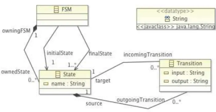
We now introduce our running example to illustrate CVL and the issues raised when developing an MSPL. Running Example. Let us consider the Finite-State Machine (FSM) modeling language. As shown in Figure 1, the FSM metamodel has three classes:
State, Transition, and FSM. The metamodel defines
some rules and constraints: a finite state machine has necessarily one initial state and a final state; a transi-tion is necessarily associated to a state, etc. Some other rules may be expressed with OCL constraints (they are not in Figure 1 for conciseness), for example, to specify that there are no States with the same name.
Using CVL and the metamodel of Figure 1, we can define a family of finite state machines. As shown in Figure 2, the V AM is composed by a set of VSpecs, while the VRM is a list of variation points, binding the V AM to the BM . The BM is a set of states and transitions conforming to the metamodel presented in Figure 1. The schematic representation of Figure 2 de-picts a V AM (left-hand side) with 6 boolean choices
(e.g., V S5and V S6 are mutually exclusive) as well as a
3
realization layer in the current CVL specification 4
Fig. 1 FSM metamodel.
VRM that maps V S3, V S2, V S5and V S6to transitions
or states of a base model denoted BM .
VAM t1# t3# t2# Object#Existence1# Link#Existence1# Link#Existence2# Link#Existence3# A B# C# VS1# VS6# VS4# VS5# VRM BM VS2# 0..1# VS3#
Fig. 2 CVL model over an FSM base model.
Considering the MSPL of Figure 2, it is actually possible to derive incorrect FSM models even start-ing from a valid BM and valid configurations of VAM. This is illustrated in Figure 3. Configuration 1
gener-t1# t2# A C# 0# 1# 1# 0# 0..1# 1# 1# 1# 1# 0# 0# 0..1# 0# 1# t3# A C# 1# 1# 0# 1# 0..1# 1# 1# t1# t3# A B# C#
Derivation Derivation Derivation Configuration 1# Configuration 2 Configuration 3
Fig. 3 Configuration and derivation of FSMs.
ates a correct FSM model, i.e., conforming to its meta-model. Conf iguration 2 and Conf iguration 3, despite being valid configurations of the VAM, lead to two un-safe products. Indeed, the FSM model generated from
Conf iguration2 is not correct: according to the
meta-model, an outgoing transition must have at least one target state, which does not hold for transition t1. In the case of Conf iguration 3, the derived product model has the incoming transition t3 without a source state, which also is incorrect with respect to the metamodel. Even for a very simple MSPL, several unsafe prod-uct models can be derived in contradiction to the
in-tention of an MSPL designer. In practice, specifying a correct MSPL is a daunting and error-prone activity due to the fact that the number of choices in the VAM, the number of classes and rules in the metamodel and the size of the VRM can be bigger.
The problem of safely configuring a feature or a de-cision model is now well understood [8]. Moreover, sev-eral techniques exist for checking the conformance of a model for a given modeling language. The connection of both parts (the VAM and the set of base models) and the management of the realization layer are still crucial issues [40, 6, 38, 18, 13].
3 Generating Counterexamples
We argue that the realization layer may concern at least two kinds of users:
– designers of MSPLs in charge of specifying the VAM, the BMs, as well as the relationships between the VAM and the BMs (V RM )(see CV L of Definition 1); – developers of derivation engines in charge of
au-tomating the synthesis of model products based on a selection of features (Choices) (function δ of Def-inition 1);
Incorrect derivation engines or realization models may authorize the building of unsafe products. The ma-jority of the existing work target scenarios in which an existing MSPL has been designed and seeks to first check its consistency, then to generate unsafe product models – pointing out errors in the MSPL. These tech-niques are extremely useful but assume that a generic derivation engine exists and is correct for the targeted modeling language – which is hardly conceivable in our case. Moreover, designers of MSPLs are likely to per-form typical errors for a given modeling language (e.g., FSM).
3.1 Counterexamples to the Rescue
We precisely want to provide support to the two kinds of users in their activities. Specifically, we are interested on finding MSPLs that apparently would derive mod-els that respect the domain modeling language, as they have a correct variability model and a conforming base model, but however, either their VRM or their deriva-tion engine were incorrectly designed. Definideriva-tion 2 for-malizes this kind of MSPL as counterexamples.
Definition 2 (Counterexample of MSPL) A
coun-terexample CE is an M SP L in which:
– There exists at least one valid configuration in VAM: CV AM 6= ∅;
– ∃ c ∈ CV AM, δ (CV L, c , BM ) = DM′ such that
DM′ does not conform to its modeling language.
The expected benefits are as follows:
– SPL designers in charge of writing CVL models, can better understand the kinds of errors that should be avoided (Figure 3 gives two “antipatterns”). – developers of derivation engines can exploit
coun-terexamples as testing oracles, anticipating the kinds of inputs that should be properly handled by their implementation. Furthermore, they can enrich the derivation engine with domain specific validation rules. In addition, specific error reports can be gen-erated when an MSPL is incorrect, inspired by the catalogue of counterexamples.
3.2 Overview of the Generation
In order to systematically generate counterexamples of MSPLs, we have defined a set of activities that can be performed for this purpose. Figure 4 presents an overview of the process that generates a single coun-terexample, as well as the input and output for the different phases. We have divided the process into four phases, which are explained in details in the following subsections; the second and the third phases are part of the greater activity of generating a CVL model.
1. The first phase is the set up of the input that will be taken into account; different activities can be per-formed, depending on the input.
2. The second phase is the generation of a random vari-ability model and of a valid random configuration. 3. The third phase is the generation of the
relation-ships between the VAM and the base model ele-ments, i.e., the variability model (VRM).
4. The fourth and last phase is to identify whether the generated model is a counterexample or not. In case it is not, we go back to the second step.
3.3 Set up input
Generally, companies that use or decide to set up a product line already have an initial set of core assets. In the case of MSPLs, if the models are not available, it is common to have the metamodel and the well-formedness rules of the modeling language. Considering this, the metamodel and the rules of the domain-specific modeling language are a starting point to generate a CVL model. Our approach is adaptable to work with
both cases, whether the models are available or only their metamodel. In the case they are not available, we apply randomizations over the metamodel to create random models. These random instances populate the Base Model, and their correctness is checked against the metamodel and the well-formedness rules. If a cre-ated model is not correct, this instance is discarded. In the case of the FSM modeling language, the checked well-formedness rules are: if the initial state is different of the final, if the FSM is deterministic and if all the states are reachable. On the other hand, if we already have a set of models, we can use mutation operators to increase the number of samples, or just not modify the base models. Mutations operators are basic CRUD (Create, Read, Update, Delete) operations on the base model that are applied randomly.
3.4 Generate VAM and Resolution
For generating the V AM and the V RM , the following parameters are required:
– The maximum depth of the V AM (MAX DEPTH) and the maximum number of children for each V Spec
(MAX CHILDREN).
– The percentage of V Specs that will be linked to variation points (LINK PERCENT). For example, in Figure 4, the V AM was generated with a per-centage of 66%, as four out of six V Specs are linked to V P s.
Once the BM is established and the parameters have been set, we take them as input to start the genera-tion of the CVL model. First, if the V AM is not pro-vided by the user, we generate it, creating a root V Spec and its children. The number of children is decided randomly, ranging from 0 to MAX CHILDREN. The
V Speccreation is repeated for each generated child
un-til the (MAX DEPTH) is reached or there are no more
V Specswith children. The only imposed generation is
of the root node of the tree, after, it is a random deci-sion between creating (or not) each child.
After generating the V AM , it is necessary to check its correctness, as we are not interested in wrong V AM s. For this reason, we translate the VAM to a language that can provide us a background for analysing it. The FAMILIAR language is executable and gives support to manipulate and reason about feature models [1] (we could also rely on existing frameworks like FaMa [8]). As stated in Section 2.2, the kinds of VAM we consider in this paper are amenable to boolean feature models supported by FAMILIAR. Using FAMILIAR, we check whether the variability model is valid or invalid. If it is an invalid model, we discard it and return to the V AM
Set up input
Generate CVL
Detect Counterexample
Generate VAM and Resolution
Generate VRM t1 t3 t2 A B C VAM VS1 VS6 VS4 VS5 VS2 0..1 VS3 VAM + Resolutions t1 t3 t2 Object Existence1 Link Existence1 Link Existence2 Link Existence3 A B C VS1 VS6 VS4 VS5 VRM BM VS2 0..1 VS3 1 1 0 0..1 1 1 0 t1 t2 C Counterexamples Discard 0 1 1 0 0..1 1 1 Resolutions Metamodel BM Fig. 4 Overview.
generation step. A resolution model is necessary in or-der to resolve the variability expressed in the V AM . To generate the configuration, we create the corresponding resolution CV L element for each V Spec. Meanwhile, random values (true or false) are set for each
ChoiceRes-olution that has been created. We use standard
satis-fiability techniques to randomly generate a resolution, which is, by construction, a valid configuration of the
V AM.
3.5 Generate VRM
Once we have a correct V AM and a correct BM , we can generate the V RM to link each other. To do this, we iterate over the set of choices in the V AM , deciding if the given choice is pointed or not by a Variation Point. This decision is done based on the (LINK PERCENT) parameter. If the decision is true, we create the V P in the V RM . The type of the V P is also random. To finish the creation of the VP, we also randomize its target
over the set of model elements of the BM . Naturally, we restrict the set of the randomization with respect to the kind of V P , e.g., a LinkExistence has a random target randomized over the subset of BM references. The VRM generation can also be independent, from existing VAMs and BMs, one could then explore the possibilities of relationships between them.
3.6 Detect Counterexample
Although Figure 4 describes the process of generating one single counterexample, we iterate the process to produce a set of counterexamples. For this reason, the first parameter to be taken into account is the stopping criteria. The stopping criteria can be specified in two different ways. The first one defines a target number of counterexamples, making the process repeat until this number is reached. The second one is to set an amount of time, stopping the process after it has elapsed.
After the aforementioned steps have been performed, we have a correct CVL model, composed by a correct
V AM and a V RM created in conformance to the CVL
metamodel. We also have a valid configuration c and a correct set of models composing the BM . The next step is to derive a product model using the CVL, c and the BM. If the derived model is incorrect, in other words, having δ (CV L, c , BM ) incorrect, we have found a counterexample as states the Definition 2, and conse-quently, we add it to the oracle. If the model is correct then we discard it and we come back to the generate VAM phase, synthesising a new entire CVL model.
The derivation engine is an algorithm that visits each of the variation points in the CVL model, execut-ing them accordexecut-ing to the resolution of the variability model. Our implementation of the CVL derivation en-gine follows the operational semantics of each variation point defined in the CVL specification (for further de-tails, see the Annex A of the CVL revised submission provided in http://www.omgwiki.org/variability). To check if the derived model is correct, we relied on the EMF Diagnostician, using it as a black box to val-idate the conformance of the generated instance of the given metamodel.
As we will discuss in Section 4, these counterexam-ples can be helpful to the domain experts in charge of designing the CVL model or developing their derivation engines for their domain.
4 Tool Support
To support the process of generating counterexamples of MSPLs (exposed in the previous section), we devel-oped a dedicated tool, called LineGen. Figure 5 gives an overview of the main features of LineGen. Depend-ing on the inputs, the tool addresses different scenarios of counterexamples’ generation – from the whole explo-ration of a modeling space (in the case only a meta-model is given) to the design of a specific MSPL (the variability model and the base model can be given by the user).
Specifically, the only mandatory input for LineGen is the metamodel of the base language. Additionally, the user can choose to provide existing base model and variability model; if this is the case, LineGen will not modify these models, setting them as immutable during the generation. To generate an MSPL example or coun-terexample, LineGen synthesizes a variability model, a configuration, a base model, and a set of realization re-lationships. LineGen calls the EMF’s Diagnostician and checks the conformance of the base model with its in-put metamodel. After, LineGen checks the correctness
of the variability model and the satisfiability of the con-figuration; to do so, it uses the reasoning engine within the FAMILIAR language. If they pass, LineGen carries on generating the realization relationships, finishing the CVL model.
After everything is generated, LineGen calls the CVL derivation engine, giving as input the generated CVL model (the triplet: variability model, realization model and base model) and a configuration. The goal of the call to the derivation engine is to determine whether the derived model is conforming to its modeling language. If it is, the CVL model given as input to the derivation engine is considered as an example of MSPL; otherwise it is considered as a counterexample.
We used different technologies as part of the Line-Gen implementation. As the user interface is an Eclipse 4 RCP application, it is written in Java. The core al-gorithms of the model generation parts are in Scala; we chose to use the same language in which we pre-viously implemented the CVL derivation engine. We used the EMF API to manipulate and check the Ecore metamodels and model instances. To benefit from au-tomatic analysis of the variability model, we translated the VAM to the FAMILIAR language [21].
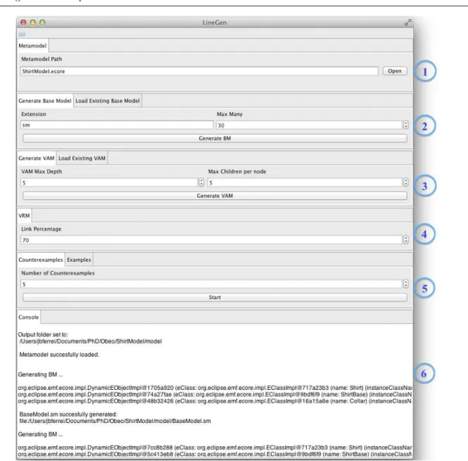
Figure 5 shows the graphical user interface of Line-Gen. The user must load the Ecore metamodel of the modeling language to be able to perform the generation steps (see 1 ). Once the metamodel has been success-fully loaded—the Console (see 6 ) shows whether Line-Gen successfully completed an operation or not—it is possible to generate a base model by pressing the Gen-erate BM button (see 2 ); a file named BaseModel is created with the chosen extension. The Max Many field should be set to limit the number of instances of a given model element.
The same process applies to the VAM generation (see 3 in Figure 5). The user specifies the maximum depth of the VAM, as well as the maximum number of children per feature. After pressing the Generate VAM button, LineGen creates a CVL model with just the VAM part defined. In the VRM tab, the user can define the percentage of features linked to a variation point in the VRM (see 4 ).
In the Counterexamples and Examples tabs (see 5 ), the user can start the generation process that will randomly search for examples or counterexamples of MSPLs. If the user chooses to use the Load Existing Base Model or Load Existing VAM tabs, LineGen uses the loaded models without modifying them and just generates VRM models. The field Number of Coun-terexamples determines when LineGen has to stop the search. The Console tab also provides exception mes-sages, in case an unexpected error occurs. More details
Fig. 5 LineGen user interface
about LineGen can be found online: https://code. google.com/p/linegen/wiki/LineGen.
5 Evaluation
The goal of this evaluation is to verify the applicability and effectiveness of the proposed approach, as well as to assess important properties of the generated counterex-amples. Regarding the effectiveness, we formulated the following question:
– RQ1. Can the approach generate counterexamples in a reasonable amount of time?
Then we seek to answer questions about the properties of the generated counterexamples, such as:
– RQ2. Does the number of counterexamples increase in a more complex domain?
– RQ3. With respect to the metamodel or the OCL rules, what errors are the most common in the coun-terexamples?
– RQ4. Is it possible to prevent the generation of coun-terexamples by the designer?
5.1 RQ1. (Applicability and Effectiveness)
Answering this question will allow us to know if the ap-proach can actually generate counterexamples and how long it takes to generate a range of counterexamples.
Objects of Study. To answer RQ1, we need to apply the proposed approach to specific scenarios and verify if it effectively produces counterexamples. As a
first scenario, we use the FSM modeling language that was presented in previous sections. As second and more complex scenario, we use the Ecore modeling language. We provide the corresponding metamodel and valida-tion rules as input for both scenarios. As previously mentioned, the FSM metamodel has 3 classes and 4 rules, while the Ecore metamodel has 20 metaclasses, 33 datatypes and 91 validation rules. We set up the parameters equally for both scenarios: the stopping cri-teria is set to the number of 100 counterexamples, the
MAX DEPTH is set to 5, the MAX CHILDREN is set
to 10 and the LINK PERCENT is set to 30%.
Experimental Setup. Once the parameters and the input are ready, we start the automatic generation of the counterexamples. The generation was performed in a machine with a 2nd Generation Intel Core I7 pro-cessor - Extreme Edition and 16GB of 1333MHz RAM memory, running under a linux 64bit with a 3.8.0 ker-nel, Scala 2.9.3 and an oracle Java Runtime Environ-ment 7.
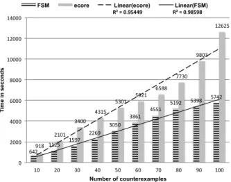
Experimental Results. The times are shown in Figure 6, ranging from 0 to 12625 seconds. For both FSM and Ecore, we could successfully find and gen-erate counterexamples in a reasonable time. The time for generating 10 counterexamples for the Ecore-based MSPL was approximately 15 minutes, which is accept-able, considering the complexity of the Ecore meta-model. Thus, as the target number of counterexample increases, we can confirm a linear growth of the time. The linear trendlines are a good fit to the obtained time
values, with R2values close to 1. Each time value is an
average of 10 executions, this was done to minimize the random effect. 642 1125 1597 2269 3050 3861 4551 5192 5398 5742 918 2101 3400 4315 5301 5921 6588 7730 9803 12625 R² = 0.95449 R² = 0.98598 0 2000 4000 6000 8000 10000 12000 14000 10 20 30 40 50 60 70 80 90 100 Ti m e i n s e c o n d s Number of counterexamples
FSM ecore Linear(ecore) Linear(FSM)
Fig. 6 Counterexamples for FSM and Ecore.
5.2 RQ2. (Counterexamples vs Domain Complexity) This research question aims at analysing the conse-quences of applying the approach in a more complex domain. Answering this question helps whether and to which extent it is more likely to design counterexam-ples (i.e., unsafe MSPLs) when the domain becomes more complex or not.
Objects of Study. To address RQ2, we compared the ratio between the number of invalid DM s and valid DM s. We made this comparison with three different modeling languages: FSM, Ecore (with the Eclipse Mod-eling Framework implementation) and UML (with the Eclipse UML2 project implementation. We classified these modeling languages in the following increasing sequence of complexity: FSM < Ecore < UML. In-deed, the FSM metamodel contains only 3 metaclasses 1 datatype and 4 validation rules. The Ecore metamodel contains 20 metaclasses, 33 datatypes and 91 valida-tion rules. Finally, the UML contains 247 metaclasses, 17 datatypes and 684 validation rules.
Experimental Setup. For each modeling language, we applied our approach to obtain 100 counter exam-ples, using the same parameters of the first experiment, and we collect the number of correct DM s we obtain. The evaluation was performed on the same computer of the previous experiment. For generating valid UML model, we do not create UML models from scratch, but we mutate existing UML models. We chose the footnote
referred set of UML models to create the BM5.
Experimental Results. The experiment resulted in the generation of 469 correct DM s for 100 amples for FSM, 292 correct DM s for 100 counterex-amples for Ecore and 52 correct DM s for 100 counter
examples for UML6. We can therefore verify the ratio
of incorrect per correct derived models. In the case of FSM, the ratio is 1 incorrect DM to 5 correct DMs, while in the case of Ecore, this ratio is 1 to 3, and for UML the ratio is 1 to 0,5. These results provide evi-dence that, as the domain modeling language becomes more complex, the chance to get a correct DM be-comes lower. In a sense, it confirms the relevance of our procedure for generating counterexamples. More impor-tantly, the practical consequence is that the designer is likely to produce much more unsafe MSPLs when the targeted modeling language is complex.
5
http://goo.gl/kC0sx 6
Source code for the experiment is available at
5.3 RQ3. (Nature of the errors)
The purpose here is to evaluate whether the errors are a violation to the structural properties of the metamodel or to the validation rules (i.e., OCL rules). Answering this question can help to understand which part of the modeling language is more likely to reveal more errors. Hence, we conducted the following experiment to inves-tigate the research question.
Objects of Study. To identify the nature of the errors in the counterexamples, we used the generation of the 100 counterexamples for the three modeling lan-guages that were previously used to answer RQ2. Our object of study is the quantity of counterexamples with errors violating the metamodel or the OCL rules.
Experimental Setup. For each modeling language, we applied our approach to obtain 100 counterexam-ples under the same parameters, and then we identify in which part of the modeling language definition is the error of the DM. The evaluation was performed using the same computer of the previous experiment.
Experimental Results. For the FSM language, among the 100 counterexamples, we generate 10 models that do not conform to the metamodel and 90 models that violate one of the validation rules. For the Ecore modeling language, among the 100 counter examples, we generate 64 models that do not conform to the meta-model and we generate 36 meta-models that violate one of the validation rules. For the UML modeling language, among the 100 counter examples, we generate 22 mod-els that do not conform to the metamodel and we gen-erate 78 models that violate one of the validation rules. We now correlate these numbers with the proper-ties of the modeling language. FSM contains only three structural rules (i.e., a state-machine must contain at least one state, one initial state and at least one final state). Most of the errors are the validation rules that are violated. Ecore contains much more structural rules (mainly lower case constraints for cardinality). There-fore lots of errors come from structural inconsistencies. Finally UML contains so many validation rules that it is unfeasible to create a valid UML model randomly. (That is why we used mutation from a set of valid UML models.) For this case we obtained much more DM s that violate validation rules expressed in OCL.
Yet, it is hard to draw definitive conclusions on whether structural or validation rules expressed in OCL participate the most in generating incorrect MSPLs. The results indicate that the kind of errors that are the most common in the counterexamples depend mainly on the domain modeling language (Ecore vs UML). It is well known, for instance, that some OCL rules can be refactored as structural constraints in the metamodel.
In a sense, it partly confirms – in the context of CVL – some of the results exposed in [9] showing there ex-ists different “styles” of expressing business or domain-specific rules within a metamodel.
5.4 RQ4. (Antipattern Detection)
The purpose of RQ4 is to evaluate the feasibility of expressing validation rules on the triplet V AM , BM ,
V RMto decrease the risk of creating invalid DM s from
a valid CV L model and a correct BM , being C the set of possible valid configurations for a valid V AM . This question helps to know if it is possible for a domain designer to detect early “bad” CVL models (acting as “antipatterns”) for a given domain.
Objects of Study. To evaluate this research ques-tion, we created two validation rules to detect antipat-tern for the FSM modeling language. Rule 1 prevents a substitution between a final state and an initial state, and vice versa. Rule 2 constrains the fact of having an object existence that targets the initial state of an FSM. These rules have been implemented in Scala and can be written in few lines using an OCL writing style, as shown in Listing 1.
Listing 1 Antipattern rules for FSM
1 d e f checkVRM ( f : FSM, vrm : VPackage ) : B o o l e a n = { 2 vrm . a s I n s t a n c e O f [ VPackage ] . g e t P a c k a g e E l e m e n t ( ) . f o r e a c h ( e=> { 3 /∗ Rule 1 : R e p l a c i n g a f i n a l s t a t e by an i n i t i a l one , and v i c e v e r s a , i s 4 f o r b i d d e n . ∗/ 5 i f ( e . i s I n s t a n c e O f [ O b j e c t S u b s t i t u t i o n ] ) { 6 var p = e . a s I n s t a n c e O f [ O b j e c t S u b s t i t u t i o n ] . g e t P l a c e m e n t O b j e c t ( ) . g e t R e f e r e n c e ( ) 7 var p1 = e . a s I n s t a n c e O f [ O b j e c t S u b s t i t u t i o n ] . g e t R e p l a c e m e n t O b j e c t ( ) . g e t R e f e r e n c e ( ) 8 i f ( ( f . g e t F i n a l S t a t e ( ) . c o n t a i n s ( p ) && f . g e t I n i t i a l S t a t e ( ) . e q u a l s ( p1 ) ) | | ( f . g e t F i n a l S t a t e ( ) . c o n t a i n s ( p1 ) && f . g e t I n i t i a l S t a t e ( ) . e q u a l s ( p ) ) ) r e t u r n f a l s e ; 9 } 10 /∗ Rule 2 : P o i n t i n g an O b j e c t E x i s t e n c e t o an i n i t i a l s t a t e i s f o r b i d d e n . ∗/ 11 e l s e i f ( e . i s I n s t a n c e O f [ O b j e c t E x i s t e n c e ] ) { 12 e . a s I n s t a n c e O f [ O b j e c t E x i s t e n c e ] . g e t O p t i o n a l O b j e c t ( ) . f o r e a c h ( p=> { i f ( f . g e t I n i t i a l S t a t e ( ) . e q u a l s ( p . g e t R e f e r e n c e ( ) ) ) r e t u r n f a l s e ; } ) } } ) 13 r e t u r n t r u e }
Experimental Setup. For the FSM modeling lan-guage, we applied our approach to obtain 100 coun-terexamples and we compare the number of valid DM s we obtain either checking the antipatterns rules or not. The evaluation was performed on the same computer that the previous experiment, as well as with the same parameters.
Experimental Results. The experimental results show that we generate 1860 correct DM s for 100 coun-terexample for FSM when the antipattern rules for CVL are activated, against 469 correct DM s for 100 counter examples for FSM when the CVL validation rules for CVL are not activated. For this domain, writing only 2 rules on the triplet of V AM , V RM , BM allowed us to decrease 4 times the risk of generating an invalid DM . Therefore, it is feasible to detect identified antipatterns using our approach, writing validation rules that detect
a priori and therefore earlier these errors.
5.5 Discussion
Besides the checking operations, the time results pre-sented in Figure 6 are mainly dependent on the follow-ing factors:
1. The time to generate a correct set of models to com-pose the BM;
2. The time to generate a correct VAM; 3. The time to generate a VRM;
These three factors are resulting from the generality and the full automation of our approach that does not require any input models. The approach gives the abil-ity of finding possible design errors without having yet designed the MSPL. This allows users to explore the design space of an MSPL, given a modeling language – this is the main scenario we initially target. However, it is possible to predefine some inputs. It could enhance the scalability of our generative process, since there is no need to spend time in generating these inputs. It may be the case when a designer of an MSPL already has an established BM. Another possible situation is when the VAM has been previously designed, as it is often one of the starting points of an MSPL. Therefore, we can claim that the conducted experiment address the
worst case input for our approach. Consequently, our
approach is sufficiently generic, as it does not assume that it is always the case of having a VAM or the BM as input. In addition, because it is fully automated, the approach does not demand a great effort to be used. Another benefit of predefining some inputs is that we could address other scenarios, like the debugging of an existing MSPL or the definition of various realization models given predefined BMs and VAMs.
By definition, an MSPL is a complex structure, com-posed by different connected models. This characteris-tic makes hard to design a correct MSPL, as errors can occur in any design phase. Given this great proneness to error, it is relevant to discuss the causes and to rea-son where is the lack of safety. For this purpose, we can analyse and give a rationale about two questions:
1. How a VAM and its analysis tools check and prevent configurations that result in incorrect DMs? 2. Is the fact of a derivation operator generate an
in-correct DM fault of the own derivation operator (derivation engine) or is it fault of how it was in-voked (realization model)?
Regarding the first question, it seems unfeasible to have a generic checker that, for any domain, could de-tect whether a configuration derives or not an incorrect model. It is rather needed to customize a derivation en-gine and/or a consistency checker (e.g., a simulator [44]) that takes into account the syntactic and semantic rules of the domain. Likewise, faulty configurations, currently not supported by the MSPL, could be better identi-fied and located. From this aspect, counterexamples can help to devise such specific simulators and oracles. For the second question, we can argue that there is a trade-off between the expressiveness of the realization model and the safeness of the derivation. On the one hand, if more restrictions are applied to the derivation engine, we limit what could be generated. Also, a realization design can be wrong in one domain, but correct in an-other. On the other hand, if the derivation engine is not customized to address the specific meanings of a mod-eling language, then it is necessary to have checking mechanisms for the VRM that takes into account the syntax and semantics of the domain. More practical in-vestigations are needed to determine when to customize the derivation engine or when to develop specific check-ing rules for the VRM. Counterexamples can be used for implementing both solutions.
6 Approach in an Industrial Case
In the last session, we evaluated our approach against well-known modelling languages; we could verify that it produces counterexamples in a reasonable time and we could also assess properties of the counterexamples. In this section, we present how the approach performs fac-ing an industrial case. First, we describe the company’s scenario; second, we report on how we could successfully apply the approach on it; and finally, we reproduce the applicability and effectiveness experiments done in the RQ1 of the evaluation.
6.1 Thales Scenario
Thales is a large company involved with different indus-try sectors (aerospace, space, defence and transporta-tion areas, etc.); they produce software intensive sys-tems, using model-based technologies, and they seek to
evolve towards a product line approach. Thales already has a well-established and functional model-based method for developing their systems and software, the ARCA-DIA, however they seek to leverage this development from single software to families of software, maintain-ing their safety and quality standard [23].
The ARCADIA method is a viewpoint-based ar-chitectural description, defining 5 different abstraction levels of a system, following the ISO/IEC 42010, Sys-tems and Software Engineering - Architecture Descrip-tion [30]. Thales’ engineers use numerous domain spe-cific modeling languages to develop integrated sets of systems according to ARCADIA. These languages are built within a set of dedicated representations to an-alyze specific problems. The language workbench pro-vides a set of customizable and highly dynamic repre-sentations working seamlessly together on top of mod-els. These representations can be combined and cus-tomized according to the concept of Viewpoints. Views, dedicated to a specific Viewpoint, can adapt both their display and behavior depending on the model state and on the current concern. The same information can also be simultaneously represented through diagram, table or tree editors.
These languages are defined as a set of 20 meta-models with about 400 metaclasses and about 200 val-idation rules; they model the ARCADIA method in an eclipse-based environment. Besides, this workbench is extensible and new languages can be defined to design specific viewpoints of a system. Therefore, leveraging product line engineering for each of these languages and domains is very expensive and error-prone; it has to be supported by automated tools.
Several stakeholders have to work during the design process on the tool chain:
– Product-line engineers who have to identify the com-monalities and the variants and in charge of design-ing the VAM and the VRM.
– Product engineers who have to create specific prod-ucts, focusing on creating valid products regarding a set of requirements.
– DSL designers who are in charge of creating or ex-tending existing DSLs (base metamodel). They de-fine where and how we can put variability within (at the M2 level) the architecture and the deriva-tion semantics [24]
The use of the proposed counter example framework aims at easing the correct cooperation between these stakeholders. It is used to provide a pragmatic approach to guide these stakeholders to design CVL model that provides only valid products.
6.2 Approach Application and Results
We applied the approach to the Thales’ representative sample model of weather balloons; this base model has 2079 model elements and 563Kb and, despite of being one single subdomain, it can serve as a pilot application for other similar areas of the organization. The set of metamodels and validation rules of ARCADIA are con-sidered as input to the approach. In contrast of what we did to evaluate the approach in a generic way (gener-ating everything else besides the metamodel), we could simplify the generation because Thales provided a vari-ability model and the aforementioned preliminary base model, narrowing down the problem space. Therefore, we fixed the VAM and the BM, randomizing only over the configurations of their variability model and gener-ating the set of variation points to compose the real-ization model. However, it was necessary to adapt the implementation to meet some technical requirements from Thales for loading and saving the models.
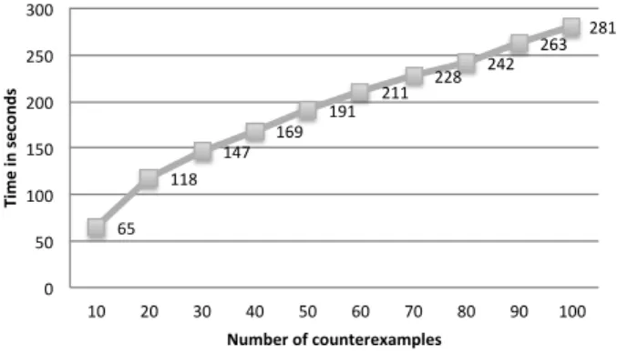
Reproducing the same experimental setup of RQ1, we performed 10 rounds and measured the average time for generating 100 counterexamples. The results in sec-onds are shown in Figure 7. We could verify that in a situation where the VAM and the BM are provided, it is around 27 times faster to generate the same amount of counterexamples, and the curve still behaves linearly.
65 118 147 169 191 211 228 242 263 281 0 50 100 150 200 250 300 10 20 30 40 50 60 70 80 90 100 Ti me i n seco n d s Number of counterexamples
Fig. 7 Counterexamples for ARCADIA sample model.
About 30% of the models generated for this domain were wrong, meaning that, in average, if we randomly define realization relationships among the features and the model elements of this domain, almost one third can result on counterexamples. Another interesting result is the fact that only one OCL rule added to the VRM can remove 50% of the counterexamples (Forbidden an object existence on a specific kind of model element “EventSendCallAction”) and 80% of the counterexam-ples can be removed in writing 8 basic OCL rules. With this example, we can show that the generation of
coun-terexamples from a reference model can help to detect some anti-patterns that can be easily constrained and detected for a particular domain. The result is the im-provement of the use of CVL in this industrial context an early detection of CVL model that capture invalid products.
7 Related Work
MSPLs. Different variability modeling approaches have been proposed. Annotative approaches derive concrete product models by activating or removing parts of the model. Variant annotations define these parts with the help of, for example, UML stereotypes [45] or presence conditions [13, 18, 15]. Compositional approaches asso-ciate model fragments with product features that are then composed for a particular configuration (i.e., com-bination of features). For instance, Perrouin et al. of-fer means to automatically compose modeling assets based on a selection of desired features [32]. Apel et al. propose to revisit superimposition technique and ana-lyze its feasibility as a model composition technique [4]. Dhungana et al. provide support to semi-automatically merge model fragments into complete product line mod-els [19]. Annotative and compositional approaches have both pros and cons. Voelter and Groher illustrated how negative (i.e., annotative) and positive (i.e., composi-tional) variability [42] can be combined. Delta
model-ing [35, 11] promotes a modular approach to develop
MSPL. The deltas are defined in separate models and a core model is transformed to a new variant by applying a set of deltas.
The variability realization layer of CVL, as exposed in Section 2.2, provides the means to support annota-tive, compositional or transformational approaches [39, 28]. Therefore we believe our work is applicable to a wide range of existing MSPL approaches.
Verification of SPLs. Some techniques specifi-cally address the problem of verifying SPL or MSPL[5]. The objective is usually to guarantee the safe
composi-tion of an SPL, that is, all products of an SPL should
be “safe” (syntactically or semantically). In [40], Ba-tory et al. proposed reasoning techniques to guarantee that all programs in an SPL are type safe: i.e., absent of references to undefined elements (such as classes, meth-ods, and variables). At the modeling level, Czarnecki et
al. presented an automated verification procedure for
ensuring that no ill-structured template instance (i.e., a derived model) will be generated from a correct con-figuration [18]. In [13, 12], the authors developed effi-cient model checking techniques to exhaustively verify a family of transition systems against temporal prop-erties. Asirelli et al. proposed a framework for formally
reasoning about modal transition systems with variabil-ity [6]. In [2], Alfe´erez et al. applied VCC4RE (for Vari-ability Consistency Checker for Requirements) to verify the relationships between a feature model and a set of use scenarios. Zhang et al. [44] developed a simulator for deriving product models as well as a consistency checker. Svendsen et al. present an approach for auto-matically generating a testing oracle for train stations expressed in CVL [38].
Some of this work generate counterexamples when the property of safe composition is violated, typically for presenting to a developer an error in the specifi-cation of an SPL. In our approach, the goal is not to produce unsafe products of an existing MSPL, but to generate unsafe MSPLs. We do not assume variabil-ity models, models or configurations as inputs and the approach is fully automated. We thus target scenar-ios that go beyond debugging an existing MSPL. Our objective is rather to prevent the unsafe specification of realization models, i.e., generated counterexamples act here as “anti-patterns” that should prevent practi-tioners in specifying unsafe MSPLs. Another important difference is that verification techniques previously de-scribed assume that the derivation engine is correct. In our context, we cannot formulate the same hypothesis and have rather the crucial needs to implement new and robust derivation engines – each time a new modeling language is used in the MSPL. We provide quantitative evidence that the specificity of the modeling language should be taken into account. The generation of coun-terexamples aims at producing testing “oracles” and guide developers when building a derivation engine.
Techniques for combinatorial interaction testing of feature models (the V AM part of CVL) [31, 33, 26] have been proposed. As future work we plan to consider their use as part of our generation process.
Classification. In [41], Th¨um et al. present a
clas-sification and survey of analysis strategies for SPLs. Ac-cording to their classification, our work can be seen as an incremental product-based approach analysis, due to the fact that we produce and explore sample products. A limitation that follows every product-based approach is that it takes exponential effort to guarantee that the SPL model is safe. Given the design space complexity of a modeling language, it is unlikely to generate every possible counterexamples. We thus rely on randomiza-tion to synthesize a finite set of counterexamples.
Besides, we recognize as a limitation the fact that, in our experiments, we did not consider coverage criteria of counterexamples. It is hard to specify such coverage criteria for any domain-specific modeling language. For example, it is hard to synthesize a set of base models that covers any constructs offered by a language. Our
approach has the merit of being agnostic of a domain and leaves to the user the choice of how exhaustive he/she wants to search the problem space. Consider-ing this scenario, our target is not to directly provide mechanisms to verify the safety of an existing SPL (i.e., ensuring there is no unsafe product). As motivated by our industrial case study with Thales, we rather aim to help the engineers in charge of building mechanisms for MSPLs.
Verification and debugging of models. Numer-ous techniques have been proposed for debugging or verifying consistency of models or model transforma-tions (e.g., [7, 20]). These works do not address specific issues of MSPL engineering, especially those related to the realization layer.
8 Conclusions and Future Work
Because of the combinatorial explosion of possible de-rived variants, the great variety and complexity of its models, correctly designing a Model-based Software Prod-uct Line (MSPL) has proved to be challenging. It is easy for a developer to specify an incorrect set of map-pings between the features/decisions and the modeling assets, thus authorizing the derivation of unsafe prod-uct models in the MSPL. In this continuation paper, we have presented a systematic and fully automated approach to explore the design space of an MSPL. The main objective of the approach was to generate coun-terexamples of MSPLs, i.e., MSPLs that can produce invalid product models. This kind of MSPL can be used to test derivation engines or provide examples of invalid VRMs, which could serve as a basis to establish antipat-terns for developers.
For this purpose, we have formalized the concepts of an MSPL, based on the Common Variability Lan-guage (CVL), as well as the concept of a counterexam-ple. We explained in details each step of our generative approach and illustrated it with a running example. The tool LineGen, built on top of CVL and model-ing technologies, supports the generative process. It en-ables practitioners to explore the whole design space of a given modeling language but also to focus on a specific MSPL with a pre-defined variability and base models. We performed experiments to assess the applicability and effectiveness of the tool-supported approach. The conducted experiments allowed us to evaluate the ap-proach when applied to different modeling languages, at different scales of complexity. We could successfully generate counterexamples for each modeling language in a reasonable amount of time, which could be dras-tically reduced when the approach received additional input. In addition, we explored the natures of errors
found in the counterexamples and our ability to detect antipatterns. We also reported on our experience when instantiating the approach and LineGen in an industrial context.
As future work, we seek to automate as much as possible the safe construction of an MSPL, using the counterexamples and examples as material to design an MSPL. In particular, we want to combine machine-learning techniques to automatically classify the coun-terexamples w.r.t. the kinds of error. Our hope is to pro-vide an efficient approach to synthesize domain-specific rules that can prevent earlier the detected anti-patterns.
References
1. Acher, M., Collet, P., Lahire, P., France, R.: Familiar: A domain-specific language for large scale management of feature models. Science of Computer Programming (SCP) Special issue on programming languages p. 22 (2013). DOI http://dx.doi.org/10.1016/j.scico.2012.12. 004
2. Alf´erez, M., Lopez-Herrejon, R.E., Moreira, A., Amaral, V., Egyed, A.: Supporting consistency checking between features and software product line use scenarios. In: K. Schmid (ed.) ICSR, Lecture Notes in Computer Sci-ence, vol. 6727, pp. 20–35. Springer (2011)
3. Apel, S., Batory, D., Kstner, C., Saake, G.: Feature-Oriented Software Product Lines. Springer (2013) 4. Apel, S., Janda, F., Trujillo, S., K¨astner, C.: Model
super-imposition in software product lines. In: R.F. Paige (ed.) ICMT, Lecture Notes in Computer Science, vol. 5563, pp. 4–19. Springer (2009)
5. Apel, S., Rhein, A.v., Wendler, P., Grosslinger, A., Beyer, D.: Strategies for product-line verification: Case studies and experiments. In: Proceedings of the 2013 Interna-tional Conference on Software Engineering, ICSE ’13, pp. 482–491. IEEE Press, Piscataway, NJ, USA (2013). URL http://dl.acm.org/citation.cfm?id=2486788.2486852 6. Asirelli, P., ter Beek, M.H., Gnesi, S., Fantechi, A.: For-mal description of variability in product families. In: E.S. de Almeida, T. Kishi, C. Schwanninger, I. John, K. Schmid (eds.) SPLC, pp. 130–139. IEEE (2011) 7. Baudry, B., Ghosh, S., Fleurey, F., France, R.B., Traon,
Y.L., Mottu, J.M.: Barriers to systematic model transfor-mation testing. Commun. ACM 53(6), 139–143 (2010) 8. Benavides, D., Segura, S., Ruiz-cort, A.: Automated
Analysis of Feature Models 20 Years Later : A Litera-ture Review. Information Systems 35(6) (2010) 9. Cadavid, J.J., Baudry, B., Sahraoui, H.A.: Searching the
boundaries of a modeling space to test metamodels. In: ICST, pp. 131–140 (2012)
10. Chen, L., Babar, M.A., Ali, N.: Variability manage-ment in software product lines: a systematic review. In: SPLC’09, pp. 81–90 (2009)
11. Clarke, D., Helvensteijn, M., Schaefer, I.: Abstract delta
modeling. In: Proceedings of the 9th GPCE’10
con-ference, GPCE ’10, pp. 13–22. ACM, New York, NY, USA (2010). DOI 10.1145/1868294.1868298. URL http: //doi.acm.org/10.1145/1868294.1868298
12. Classen, A., Heymans, P., Schobbens, P.Y., Legay, A.: Symbolic model checking of software product lines. In: ICSE’11, pp. 321–330. ACM (2011)