HAL Id: hal-00452955
https://hal.archives-ouvertes.fr/hal-00452955
Submitted on 13 Nov 2018
HAL is a multi-disciplinary open access
archive for the deposit and dissemination of
sci-entific research documents, whether they are
pub-lished or not. The documents may come from
teaching and research institutions in France or
abroad, or from public or private research centers.
L’archive ouverte pluridisciplinaire HAL, est
destinée au dépôt et à la diffusion de documents
scientifiques de niveau recherche, publiés ou non,
émanant des établissements d’enseignement et de
recherche français ou étrangers, des laboratoires
publics ou privés.
Mass customization and configuration: requirement
analysis and constraint based modelling propositions
Michel Aldanondo, Khaled Hadj-Hamou, Guillaume Moynard, Jacques
Lamothe
To cite this version:
Michel Aldanondo, Khaled Hadj-Hamou, Guillaume Moynard, Jacques Lamothe. Mass customization
and configuration: requirement analysis and constraint based modelling propositions. Integrated
Computer-Aided Engineering, IOS Press, 2003, 10 (2), pp.177-189. �hal-00452955�
Mass customization and configuration:
Requirement analysis and constraint based
modeling propositions
Michel Aldanondo
a, Khaled Hadj-Hamou
a, Guillaume Moynard
a,band Jacques Lamothe
aaCentre de G´enie Industriel, Ecole des Mines d’Albi-Carmaux, Campus Jarlard, 81013 Albi CT Cedex 09, France Tel.: +33 0 5 63 49 32 34; Fax : +33 0 5 63 49 31 83;
E-mail:{Michel.Aldanondo, Khaled.Hadjhamou, Guillaume.Moynard, Jacques.Lamothe}@enstimac.fr bLapeyre-GME, 2-4 rue Andr ´e Karman, 93200 Aubervilliers, France
E-mail: [email protected]
Abstract. The purpose of this paper is, on the one hand, to identify to define and classify customization requirements and, on
the other hand, to evaluate how generic modeling and configuration assistance within the Constraint Satisfaction Problem (CSP) framework can fulfil the requirements. The aim is to provide commercial configurator knowledge base designers with constraint based generic modeling elements for customizable industrial product. A first part recalls the main trends of the configuration problem. In a second part divided in four sections corresponding with different requirement set; each section proposes a definition of the requirement set, some CSP based modeling elements and a discussion about adequacy of relevant configuration assistance techniques.
1. Introduction
In order to improve their competitiveness, compa-nies try to launch on the market products with cus-tomization capabilities. Therefore, they include con-figuration software (configurator) in their information system. In consequence, most of the ERP providers include in their software packages configuration mod-ules (see the surveys in [18]). In order to work, these configuration modules require a generic model of the product, which is most of the time not defined by a computer science specialist. Therefore, a strong need for friendly generic modeling approaches and relevant tools is rising in order to set up configurators in industry. Many papers dealing with configuration are more in-terested by a solving approach and the relevant generic modeling problem is most of the time not addressed. As Wielinga explains in [27] “Many authors prefer a parsimonious set of knowledge structures that suit their favorite problem solving method or their domain”. Ori-ented towards configuration requirements and
model-ing, our contribution targets two goals. The first one, dealing mainly with product generic modeling require-ments, is to identify and to classify the product cus-tomization possibilities that should be fulfilled by con-figurators. The second one, dealing with modeling, is to analyze how the Constraint Satisfaction Problem (CSP) framework can handle these modeling require-ments and to comment how existing processing ap-proaches can assist the configuration process.
We first recall configuration definition basics, dis-cuss about the people involved in the configuration process, point out two kinds of configurators, under-line general modeling needs and justify our CSP based modeling choice. Then we identify a first set of mod-eling requirements corresponding with what we call the “central problem” and provide modeling elements. Then, in order to match other particularities of in-dustrial problems, we sequentially add modeling re-quirements to this “central problem” and analyze how CSP based generic modeling elements can fulfill them. These complementary elements gather: product
de-scriptive approach, tailored or parametric component, layout definition and hierarchical bill-of-materials.
Our intention is therefore to propose and discuss generic modeling elements without focusing on prob-lem solving. We are clearly interested in identifying requirements and showing how CSP can be used to rep-resent various aspects of product generic modeling for the configuration problem. A “custom storage system” provided by the Lapeyre Company will be used as an example to illustrate our ideas all through this paper.
2. General aspects of configuration, configurators and modeling
This section recalls general aspects of configuration, introduce the product generic modeling need and justify our CSP based approach.
2.1. Configuration and configurator elements of definition
From significant works achieved concerning config-uration [7,12,15,22], and [1], common features defin-ing configurdefin-ing are:
– hypothesis: a product is a set of components, – given: (i) a generic model of a configurable
prod-uct able to represent a family of prodprod-ucts with all possible variants and options, in which a generic model is a set of components plus a set of vari-ous constraints; and (ii) a set of customer require-ments, in which each requirement can be expressed by a constraint,
– configuring can be defined as “finding at least one
component set that satisfies all the constraints”. A configurator is a software package that assists the person in charge of the configuration task. It is com-posed of a knowledge base that stores the generic model of the product and a set of assistance tools that helps the user finding a solution or selecting components. In any case, the fundamental assistance requirement is to guarantee the consistence of the configured product with both generic model and customer requirements.
2.2. Two classes of configuration situations
According to the previous definition, configuration can exist in any customer/supplier relation when defin-ing the product object of a deal. It is nevertheless
possible to identify two main classes of configuration problems and relevant configurators.
The first class deals with the selling side and is con-ducted by the sales teams of companies. In that case, the cycle time order of magnitude for setting a solu-tion is less than an hour and sometimes less than a minute when configuring on line on a web site for ex-ample. This is the target of the ERP configuration mod-ules that assist the Business to Customer (B2C) cus-tomer/supplier relation and need to be able to support mass configuration or a great amount of configuration tasks (for example: 1 to 100 configuration tasks per day).
The second class is close to a product design activity and is mainly achieved by the research and development teams of companies. An order of magnitude of the cycle time to provide a solution could be between a week and a month. In most of these cases, previous ERP configuration modules can not be used and specific configurators are necessary. For that class of problems, the customer/supplier relation is more on the Business to Business side (B2B) and the number of configuration tasks that needs to be achieved is rather small (no mass configuration, for example: from 1 to 10 configuration tasks per month).
As the configurators of the second class are specific, each of them (including its generic model) needs to be designed and maintained by computer science special-ists. On the other hand, the configuration modules vided by software companies should propose (and pro-vide most of the time) a generic modeling environment enabling a non-computer science specialist to describe the generic model of the product. Our contribution is clearly positioned on the generic modeling side of the first configurator class, frequently called commercial configurator or sale configurator.
2.3. Generic product model main characteristics
In this section we list and briefly explain the main characteristics that should fulfil the generic model of the product. They will be used in the next section for justification of our a priori choice of modeling formal-ism.
2.3.1. Easy modeling
The product model and the modeling task should rely on “natural” or easy to understand concepts. The configurable product model should be clearly separated from the configuration process. A graphical represen-tation of the model is a necessity for an easy
com-prehension and a lower maintenance effort. Pieces of “visible” written code or pseudo-code (whatever the language is), source of many errors during modeling, should be avoided as much as possible.
2.3.2. Generic model expressivity and knowledge level of users
The generic model can be different according to the configurator user’s level of knowledge about the prod-uct that must be configured. For a prodprod-uct expert, a generic model gathering detailed components plus con-straints is suitable, whereas a clearer product represen-tation in terms of product characteristics is necessary to a non expert. In the work of [14] this is addressed as an explicit model (component oriented) versus an implicit model (description oriented).
2.3.3. Generic model testability
As generic models mainly rely on components plus constraints, it is necessary to have a good confidence in the model consistency. This is a hard point and the configuration technique operating on the model should be open to debugging and inconsistency detection tech-niques.
2.3.4. Structured generic model and reusability
In order to avoid redundancy of parts of generic model, a structured generic model is of interest and permits to re-use these generic model parts in generic models of different products.
2.4. Model characteristics, configuration techniques and CSP approach
Most of the works recently achieved on configu-ration rely on propositional logic, first order logic and constraint satisfaction problem (CSP) frameworks. Generic modeling with propositional logic requires a large amount of Boolean variables and Boolean rules (and, or, not), resulting models are therefore compli-cated with a low expressivity. First order logic is a good generic modeling tool but is not easy to handle by non computer science specialists, some work has been done [6] to provide some UML based graphical formalism avoiding coding.
The utilization of “pure” CSP, introduced in [13], presents interesting concepts for configuration, but we will see, in Section 3.1.2, why its dynamic extension, the DCSP, proposed in [16] and discussed in [23], is far much better for configuration problems handling.
The clear separation between the model and the propagation or resolution techniques, the concepts of variables/domains/constraints natural for non computer specialist and good graphical representation possibili-ties make CSP a good candidate for configuration mod-eling.
The CSP concepts, variables and constraints fit two possible configurable product descriptions: set of com-ponents and/or set of characteristics. Furthermore, the work of [21] exploiting the notion of preference in CSP allows CSP based configurator to take into account the preference of the user during the configuration process. In terms of model testability, some works [11] and [20] have presented some possibilities about CSP model debugging and inconsistency detection, but the proof of full consistence model still relies in the com-plete analysis of the solution space. In order to avoid this last drawback, consistency restoration and expla-nation during configuration can be supported by CSP techniques as explained in [3].
CSP approaches do not deal easily with structural aspects. Very little work has been done in this field, composite CSP has been proposed by [17] and some extensions of Dynamic CSP trying to match this as-pect have been discussed in [25]. As far as we know, this is clearly not a good point for CSP utilization in configuration.
The kinds of product where various aspect of CSP based configuration have been studied are diverse. A car configuration problem introduced in [16] and dis-cussed by [19,20], and [25], an industrial mixer [23], a machining operation [8], and an automotive wiring system [2] are typical examples of product where CSP based configuration has been used. For these works, it must be noted that: the car and industrial mixer product model examples have been used to illustrate theoreti-cal points of CSP based processing, while the goal of the works dealing with machining operation and auto-motive wiring system examples was to have a product specific operating configurator without providing any new theoretical points. An interesting survey of prod-uct customization variety has been reported [22] but without CSP based support. Our contribution, there-fore aims to study the diversity of product customiza-tion problems, or product modeling requirements, and how it can be handled with CSP based elements. This is the aim of the rest of the paper.
Book
Case
Low
Cabinet
High
Cabinet
72
or
2
16
144
72
Fig. 1. Basic problem.
3. Modeling requirements and generic modeling elements
In this chapter, we first present what we call the “cen-tral problem”, then each following section will describe some additional modeling requirements to the central problem. For each section, the configuration problem hypotheses are defined or refined, an example is given for clarification and a CSP based model is provided and discussed.
3.1. From basic to central configuration problem 3.1.1. Basic configuration problem and CSP approach
The simplest configuration problem can be defined as follows:
– h1: all the components are “standard” or
com-pletely defined, it is not possible to create a new component during the configuration task,
– h2: the components are gathered in groups, each
component must belong to only one group, the pur-pose of the group notion is to gather components that support the same functionalities,
– h3: each group is present in any configured
prod-uct,
– h4: the constraints represent the allowed
combi-nations of components,
– h5: the customer or configurator user requirement
corresponds with the selection of one component in each group,
– h6: a configured product is a component set,
sat-isfying both constraints and requirements, where one and only one component must be selected in each group. LC LC72P LC72W BC BC72P BC216P BC72W BC216W HC HC144P HC144W
Fig. 2. Basic problem CSP model.
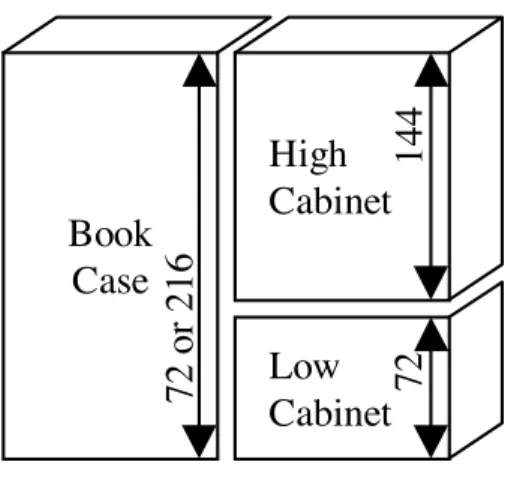
The example of Fig. 1, a “custom storage system”, illustrates this problem. The generic product gathers 3 components: a Bookcase (BC), a High Cabinet (HC) and a Low Cabinet (LC), where:
– any component of each group exists in two
fin-ishes: Painted (P) or Wood (W),
– the BC height can be 72 cm or 216 cm, LC height
is 72 and HC height is 144,
– 3 groups exist (i) BC:{BC72P, BC72W, BC216P,
BC216W}, (ii) LC: {LC72P, LC72W}and (iii) HC:{HC144P, HC144W}
– a single constraint states that any configured
prod-uct must be of the same color.
CSP, defined in [13] as a triplet X, D, C where X is a set of variables, D a set of finite domains (one for each variable) and C a set of constraints (defining the possible combinations of variables value), matches this basic problem. Each group of components is associ-ated with a variable. Each component corresponds with one value of the variable. The constraint (solid lines of Fig. 2) represents the allowed combinations of com-ponents. A generic model of the product of example 1 could be as the one shown in Fig. 2.
3.1.2. Central configuration problem and DCSP approach
This previous problem is extremely rare. Very fre-quently, the existence of a group of components is op-tional or restricted for product feasibility reason or cus-tomer wishes. Therefore, two kinds of groups must be defined: the groups which always exist in any config-ured product and the ones that may exist according to the customer requirements or product feasibility rea-sons. The central configuration problem can therefore be described as follows:
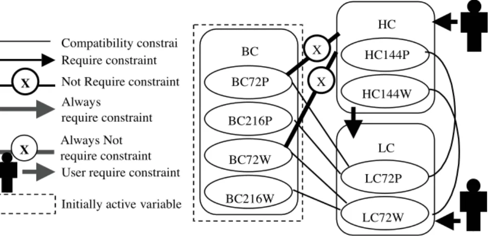
LC LC72P LC72W BC BC72P BC216P BC72W BC216W HC HC144P HC144W X X
X Always Not require constraint
Require constraint
X Not Require constraint Always
require constraint
User require constraint Initially active variable Compatibility constrai
Fig. 3. Central problem DCSP model.
– h1, h2, h6: unchanged
– h3 – a group is either always present in any
con-figured product or its existence depends on: (i) the existence of other groups and/or (ii) the selection of other components,
– h4 – the constraints represent the allowed
combi-nations of (i) components and/or (ii) group exis-tences,
– h5 – the customer or configurator user requirement
corresponds to the selection of (i) one component in each group and/or (ii) decision of a component group existence.
The example of 3.1.1 is modified with the addition of the following constraints:
– The Bookcase must be present in all configured
Storage Systems.
– The High Cabinet can exist if and only if a Low
Cabinet exists and the Bookcase is 216 cm high. This “central problem” is supported by most of the configurator packages provided by software companies and is frequently associated with what is called “pick to order” or “assemble to order” industrial situations.
DSCP, proposed in [16], adds to “pure CSP” the notions of:
– Initial variables: variables that exist in any
config-ured product.
– Compatibility constraints: equivalent to the
con-straints defined in Section 3.1.1.
– Activity constraints: allowing to control the
vari-able existence in the following ways:
∗ Require: a specified value of a variable “x” im-plies the existence of the variable “y”,
∗ Always Require: any value of a variable “x” (or “x” exists) implies the existence variable “y”,
∗ Not Require: a specified value of a variable “x” implies the non existence of the variable “y”, ∗ Always Not Require: any value of a variable
“x” (or “x” exists) implies the non existence of the variable “y”.
A generic model of the central problem example could be as the one shown in Fig. 3. It is clear that DCSP matches exactly the “central problem” requirements. In the following sections we are going to show that the presented requirements are not sufficient to take into account various industrial situation needs and provide complementary requirements and analyze how DCSP can fulfil them.
3.2. Central problem extension and complementary modeling elements
3.2.1. Physical versus descriptive model
The previous model of Fig. 3 is a “physical” model because each variable corresponds with a group of com-ponents. But very often, for a non product expert, it is necessary to define “descriptive” attributes that do not correspond with a component group. In that modeling approach, the values of the descriptive attributes permit to identify a component (for example the height and the color allow identifying a component). The advan-tages are, on the one hand, that descriptive attributes (defined by the person in charge of modeling) can be much more expressive for the customer than a list of components (that does not interest the customer most of the time) and, on the other hand, that configuration models can involve much less configuration variables and constraints. But the second approach needs to maintain identification tables or functional constraints
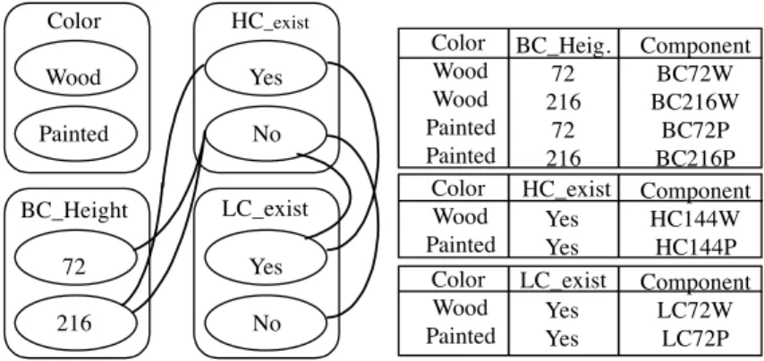
Color Wood Painted HC_exist Yes No LC_exist Yes No BC_Height 72 216 Color Wood Wood Painted Painted BC_ Heig . 72 216 72 216 Component BC72W BC216W BC72P BC216P Color Wood Painted LC_exist Yes Yes Component LC72W LC72P Color Wood Painted HC_exist Yes Yes Component HC144W HC144P
Fig. 4. Central problem descriptive model. allowing to derive the component list from the values
of the descriptive attributes.
The example of Fig. 3 is presented in Fig. 4 with this second modeling approach with the same DCSP for-malism. The four descriptive attributes, necessary to represent exactly the same set of solutions, correspond with the color (wood/painted) the book case height (72/216) the existence of the lower cabinet and higher cabinet (yes/no). The component identification tables permit to derive, from the four previous variables, the final result of configuration as a set of BC, LC and HC components.
3.2.1.1. Extended definition of the central problem.
In the first definition, components were gathered in groups. With the descriptive approach we added de-scriptive attributes and values. We therefore introduce the notion of configuration variables that gathers these two elements and can propose the following definition:
– H1 – All the components, “standard” or
pletely defined, are gathered in groups, each com-ponent must belong to only one group. Each group is associated with a configuration variable whose definition domain is a list of values equal to the component list.
– H2 – A product can be characterized by descriptive
attributes. Each descriptive attribute is associated with a configuration variable whose definition do-main is a list of values, where a value cannot be a component.
– H3 – A configuration variable is either always
present in any configured product or its existence depends on: (i) the existence of other configu-ration variables and/or (ii) the selection of other configuration variable values.
– H4 – The constraints represent the allowed
combi-nations of (i) configuration variable values and/or (ii) configuration variable existences,
– H5 – The customer or configurator user
require-ment corresponds to the selection of (i) one value for each configuration variable and/or (ii) decision of a configuration variable existence.
– H6 – A configured product is a set of configuration
variable values, satisfying both constraints and re-quirements, where (i) one and only one compo-nent is selected in each group and (ii) one and only one value is selected for each existing descriptive attribute.
3.2.1.2. Discussion. Globally the descriptive model
targets to displace the configuration from a component plus constraint problem to a descriptive attribute plus constraint problem plus component identification ta-bles. This permits a kind of disconnection between the product configuration process and the bill-of-materials generation. The interest of this disconnection lies in a kind of delinking of selling and manufacturing con-cerns allowing remote configuration possibilities for sale without handling all the product technical data. Therefore this approach is of interest for commercial configurators.
When there is not any descriptive attribute (i.e. all configuration variables represent component groups), this definition corresponds with the physical problem of Section 3.1.2. When all the configuration variables associated with the component groups are only present in component identification tables or functional con-straints, this definition corresponds with a “pure” de-scriptive problem. Most of the time, it is unfortunately necessary to express the requirements of the configu-rator user in terms of both component selection and product characteristic valuation. For example, when it is necessary to allow configuration by product experts (component selection) and also by non product experts (descriptive attribute valuation), the two modeling
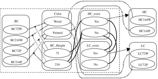
ap-Color Wood Painted BC_Height 72 216 HC_exist Yes No LC_exist Yes No BC BC72W BC216W BC72P BC216P LC LC72W LC72P HC HC144W HC144P
.
.
.
.
Fig. 5. Physical and descriptive configuration model. proaches need therefore to be mixed in a single
config-uration problem as shown in Fig. 5, where both com-ponent groups (constraints in dot lines) and descriptive attributes (constraint in solid lines) are present in the proposed model. D CSP handles this problem relying on configuration variables gathering group/component and descriptive attribute/value. The next sections will identify other kinds of attribute that will be associated with configuration variables allowing to represent other configuration modeling requirements.
3.2.2. Tailored components, component quantity and numerical constraints
3.2.2.1. Standard and tailored components. Until now,
all the components were completely defined with en-tirely frozen characteristics (hypothesis H1). Very fre-quently, industrial cases need to deal with parametric or tailored components. For example, when a door needs to be replaced in an old house, it rarely corre-sponds with a standard offer. In order to capture this market, many companies propose customization pos-sibilities that are not restricted to standard component assembling.
We therefore propose to characterize each tailored component by numerical tailoring attributes with a con-tinuous definition domain defining the range of possible values. Therefore, modeling requires to associate each tailoring attribute with a configuration variable defined on a continuous definition domain (Fig. 6).
In the example of Fig. 6, the Bookcase and the High Cabinet are now tailored components with tailoring at-tributes BC height (chosen in a range between 72 cms and 216 cms) and HC height (chosen in a range be-tween 50 cms and 144 cms).
3.2.2.2. Component quantity. In the central problem,
hypothesis H6 assumes that a configuration solution contains only one component in a group. Very often, it is necessary to model that the quantity of a selected component might be different from 1.
In that case, a quantity attribute is necessary to char-acterize the quantity selected for a component chosen in a group. This attribute can be defined either on a discrete or continuous domain. This quantity attribute must also be associated with a configuration variable.
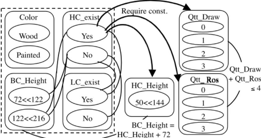
In our example of Fig. 6, the High cabinet can contain drawers and roll out-shelves. For each of them, it is possible to select a quantity between 0 and 3 thanks to the quantity attributes for drawers (Qtt Draw) and roll-out-shelves (Qtt Ros).
3.2.2.3. Numerical constraints on discrete variable.
Until now, compatibility and activity constraints were discrete. Activity and compatibility constraints repre-sented allowed the combinations of configuration vari-able values. Very frequently during modeling, it is sim-pler to define constraints through the expression of a mathematical formula that avoids a huge combinatory even when dealing with discrete variable domains.
Therefore a strong modeling requirement is to han-dle constraints expressed with formulae. These kinds of formula allow to take into account among other that some component selections or attribute valua-tions are restricted by some kind of resource (space, power, length. . . ) provided by other components or attribute values. This behavior is similar to the re-source/provide/consume elements introduced by [10] and discussed in [19].
In our example of Fig. 6, let us consider that up to four elements among Drawers and Roll-Out-Shelves
Require const. Color Wood Painted HC_exist Yes No LC_exist Yes No BC_Height 72<<122 122<<216 HC_Height 50<<144 Qtt _Draw + Qtt _ Ros ≤ 4 BC_Height = HC_Height + 72 Qtt _Draw Qtt_ Ros _ Ros 0 1 3 2 0 1 3 2
Fig. 6. Tailoring and quantity attributes with constraints. can be chosen for the High Cabinet. It is much simpler
to express this modeling requirement with a numerical constraint stating that Qtt Draw.+ Qtt Ros. ! 4 than describing in extension the possible combinations of quantity.
3.2.2.4. Numerical constraints on discrete and contin-uous variable. Before the identification of tailored and
quantity attributes, configuration variables were dis-crete. With these two continuous attributes, it is neces-sary to express constraints on continuous variables.
A first modeling solution that avoids mathematical formulae is to discretize the variable domains and to use discrete constraints. This is shown in our exam-ple of Fig. 6 with the compatibility constraint between BC height and HC existence, where BC height is dis-cretized in two intervals [72,122] and [122,216], the first interval forbids the HC existence while the second leaves the two possibilities.
When discretization is not suitable or requires a too large combinatory description, it is necessary to use a mathematical formula. This is shown in the exam-ple of Fig. 6 where a constraint, between BC height and HC height expresses that the top of Bookcase and High Cabinet must be at the same height: BC height = HC height + 72,
3.2.2.5. Tailored attribute, quantity attribute and numerical constraint example. In the example of Fig. 6, the Bookcase and the High Cabinet are tai-lored components with tailoring attributes BC height and HC height, with the following constraints:
– the top of Bookcase and High Cabinet must be at
the same height: BC height = HC height + 72,
– the High Cabinet can exist if: BC height" 72 +
50 = 122
Two new component groups, Drawers and Roll-Out Shelves, are added to the High Cabinet. A constraint states that a maximum of four elements among these groups can be chosen. This is modeled with:
– quantity attribute for drawers (Qtt Draw) and
Roll-Out Shelves (Qtt Ros),
– a numerical constraint expressing that: Qtt Draw.
+ Qtt Ros.! 4.
3.2.2.6. Discussion. As far as modeling is concerned,
configuration variables corresponding with tailoring at-tributes and quantity atat-tributes, numerical constraints, continuous variables and constraints can be added to the model of the central problem. The problem raised in this section is on the side of configuration process-ing, DCSP solving and constraint propagation require discrete variables and discrete constraints. Therefore, other processing techniques must be investigated for assisting the configuration process, which should deal with cooperation of constraint solvers dealing with dis-crete and numeric variables, some ideas for this prob-lem have been proposed in [24]. As far as we know, very few commercial configurator software programs support discrete and continuous variables, discrete and continuous constraints, and constraints expressed with formulae in a proper way.
3.2.3. Layout aspects in configuration
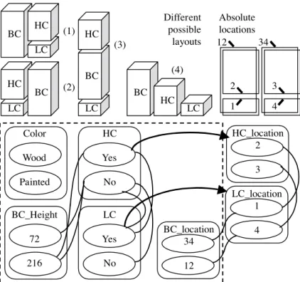
In the previous cases, the configuration result is al-ways a set of components plus attribute values. As explained in [4], a same set of components can corre-spond with two different products according to two
dif-Color Wood Painted HC Yes No LC Yes No BC_Height 72 216 HC_location 2 3 LC_location 1 4 BC_location 34 12 1 2 4 3 12 34 Absolute locations LC BC HC BC HC LC BC LC HC LC HC BC (1) (2) (3) (4) Different possible layouts
Fig. 7. Layout modeling with location attributes. ferent layouts. It is therefore sometimes necessary to
geometrically locate each selected component among others. This is close to a design activity whose aims are either to locate a component in an absolute referential or to locate the position of one component in relation to another component.
3.2.3.1. Layout with component absolute locations.
Layout requirements using absolute position can be handled thanks to the association of each component with location attributes. Each attribute is a coordinate of a referential and corresponds with a configuration variable. The values of the location attribute can be either discrete or continuous. Discrete and continuous layout constraints can link location attributes of differ-ent compondiffer-ents. These modeling elemdiffer-ents are simi-lar to quantity and tailored attributes modeling. Con-sequently, they lead to the same configuration process drawbacks.
Without layout configuration, the four layouts in the upper left part of Fig. 7 are possible. But let’s consider that only the first and second are valid: the LC must be under the HC and the BC near the LC. Then, absolute position layout modeling requires to define different possible component locations. The space is therefore mapped in 6 possible locations identified by a
num-ber: 1/lower left, 2/upper left, 3/upper right, 4/lower right, 12/left, 34/right, as described in the upper right of Fig. 7. The model, in the lower part of Fig. 7, shows that each component is characterized by a location at-tribute and compatibility constraints define the accept-able layout solutions (1) and (2).
3.2.3.2. Layout with component relative locations.
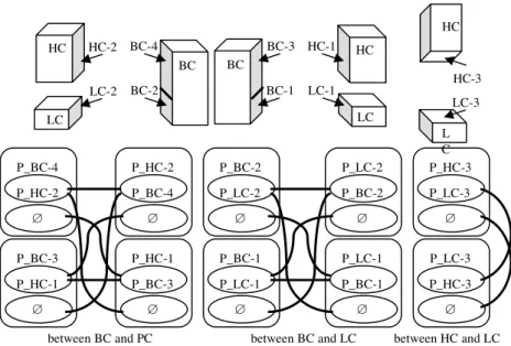
Layout requirements using relative location of compo-nent couple have been introduced with the notion of “port and connection” in [15], defining that two com-ponents can be connected through component ports (port m of component i can be connected to port n of component j). Each port is a characteristic of a com-ponent and can be associated with a comcom-ponent port attribute.
In our example, this approach requires to locate each component with respect to each other at a certain place (on, under, lined up, etc.) in a way very close to CAD systems. Therefore each component must be charac-terized by some ports, each port corresponds with a particular side (or piece of side) where a port of an-other component can be “in contact” as shown in the upper part of Fig. 8. Constraints should explain how components could be relatively located.
Layout modeling with relative location or ports is much harder to handle with a CSP based approach
HC LC HC LC BC BC HC-1 LC-1 HC-2 LC-2 BC-4 BC-2 BC-3 BC-1 HC HC-3 L C LC-3 P_BC-4 P_HC-2 ∅ P_BC-3 P_HC-1 ∅ P_HC-2 P_BC-4 ∅ P_HC-1 P_BC-3 ∅ between BC and PC P_BC-2 P_LC-2 ∅ P_BC-1 P_LC-1 ∅ P_LC-2 P_BC-2 ∅ P_LC-1 P_BC-1 ∅ between BC and LC P_HC-3 P_LC-3 ∅ P_LC-3 P_HC-3 ∅ between HC and LC Fig. 8. Layout modeling with ports and connections.
but we propose some ideas dealing with this modeling problem, such as: (i) define a configuration variable for each component port attribute, (ii) define allowed values of the component port configuration variable as the list of component ports that can be connected to it plus the value “Ø” specifying that the port is not used, (iii) define possible connections between component couples with compatibility constraints.
The model in the lower part of Fig. 8 illustrates the proposed solution. The BC has four ports (P BC-1, P BC-2, P BC-3, P BC-4), the HC three (P HC-1, P HC-2, P HC-3) and LC three (P HC-1, P LC-2, P LC-3). The definition domains of these vari-ables are the component ports that can be connected. The constraints show how three couples of components plus ports can be connected (BC,HC), (BC,LC) and (HC,LC) allowing the solutions of the previous sub-section Fig. 7.
3.2.3.3. Discussion. Configuration with layout
re-quirements is not easy to handle with our CSP based elements. When the location problem is not too com-plicated, for example when locating less than 20 pieces of furniture on a single axis with a unique coordinate, absolute position location is fine. Layout requirements taking advantage of the port and connection approach are typical of electronical product configuration. When components and possible connections are numerous, the presented CSP based model becomes quickly com-plicated and modeling and maintenance not possible.
It is clear that layout configuration is close to a design activity. Simple cases, close to schematic drawings, can be handled with commercial configurators as shown for example in the configuration problem of a train car layout addressed in [9]. But as explained in [2] configuration including hard layout problems are better solved thanks to the cooperation of configurator and CAD system.
3.2.4. Hierarchical bill-of-materials
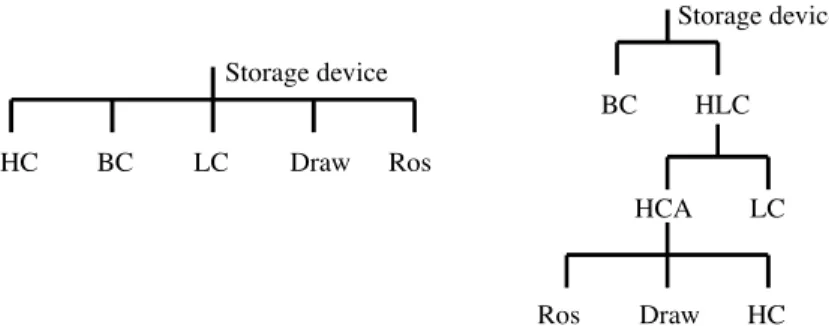
Many industrial situations require, mainly for pro-duction management reasons, to have the configura-tion result (the component set) presented as a hierar-chical materials instead of a single level bill-of-materials.
For the example of Fig. 6 gathering up to five of the components, Bookcase (BC), High Cabinet (HC), Low Cabinet (LC), Drawers (Draw) and Roll-Out Shelves (Ros); the single level bill-of-material is as shown in left part of Fig. 9. The hierarchical bill-of-material presentation need may correspond, for example, with the identification of the following sub-assemblies:
– High Cabinet plus Accessories (HCA) gathering:
High Cabinet, Drawers and Roll-Out Shelves,
– High and Low Cabinet (HLC) gathering: Low
Cabinet and High Cabinet plus Accessories, and the resulting hierarchical bill-of-materials would be as shown in the right part Fig. 9.
As this is mainly a presentation requirements, we propose to keep the previous modeling elements (CSP
HC BC LC Draw Ros Storage device BC HLC Storage device LC HCA Draw Ros HC
Fig. 9. Single level and hierarchical bill-of-materials. based generic model plus component identification
ta-bles representing single level bill-of-materials) and to add a piece of generic model allowing to derive a hierarchical bill-of-materials. The added pieces of model gather a generic hierarchical bill-of-materials plus existence conditions of each generic sub-assembly. The leaves of the generic hierarchical bill-of-materials are the component groups and the intermediate el-ements are the generic sub-assemblies of the prod-uct. The sub-assembly existence conditions correspond with functional activity constraints that modulate the sub-assembly existence in function of the variables of the CSP based generic model.
With these elements, the configuration can go as follows: (i) configuration of the product (ii) iden-tification of the component (iii) existence validation of the generic sub-assemblies (iv) hierarchical bill-of-material generation. The last step is achieved with a substitution in the generic hierarchical bill-of-materials of each component group by relevant identified compo-nent at step (ii). When a sub-assembly does not exist, direct bill-of-material links, between lower level sub-assemblies or components and upper sub-assembly of top level product, replaces the generic hierarchical bill-of-materials upstream and downstream links. Lastly, in order to differentiate each sub-assembly, each of them should be codified according to the lower level compo-nents and/or sub-assemblies.
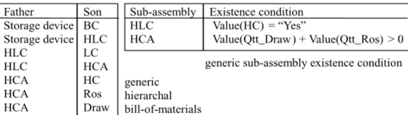
For the example of Fig. 9, these elements both pre-sented in a table form would be as shown in Fig. 10, the hierarchical bill-of-materials in the left part and sub-assembly conditions in the right part
According to these elements, the whole configura-tion process would go for example as follows:
(i) configuration process with user requirements as: Color = “Wood”, BC Height = 216, LC = “Yes”, HC = “yes”, HC Height = 144, Qtt Draw = 0, Qtt Ros = 0
(ii) component identification: BC216W (BC group), LC72W (LC group), HC144W (HC group).
(iii) sub-assembly existence validation: HLC, (iv) hierarchical bill-of-material generation: as shown in Fig. 11.
3.2.4.1. Discussion. The added pieces of the model
show how a hierarchical bill-of-materials can be gen-erated as a configuration result with our CSP based approach. Some complementary works are necessary to model a product where a same component group is present in different generic sub-assemblies or when the hierarchical bill-of-materials does not have a tree shape.
A main drawback of our entire CSP based approach, which clearly appears in this section, is that it is not easy to configure in a generative way. Generative con-figuration should be understood as the ability of config-uring a product with more than one instance of a same generic sub-assembly or with a number of instances un-known at the beginning of the configuration task. Very little work has been done in “generative configuration”, an application specific configurator has been designed for telecommunication system and is presented in [5] and very recently some ideas about duplicating vari-able groups in CSP model in order to permit generative configuration have been proposed in [26].
4. Conclusions
Our goal was to identify and classify configura-tion modeling requirements and analyze how the CSP framework could be a good support for generic model-ing and if relevant propagation and solvmodel-ing techniques were adequate.
In terms of identification of requirements and generic modeling, we started with the central problem and a DCSP physical model composed of (i) variables, de-fined on a discrete domain, associated with component groups, and (ii) compatibility and activity discrete con-straints.
Father Storage device Storage device HLC HLC HCA HCA HCA Son BC HLC LC HCA HC Ros Draw Sub-assembly HLC HCA Existence condition Value(HC) = “Yes” Value(Qtt_Draw) + Value(Qtt_Ros) > 0 generic sub-assembly existence condition generic
hierarchal bill-of-materials
Fig. 10. Added pieces of generic model for hierarchical bill-of-materials.
BC HLC Storage device LC HCA Draw Ros HC BC216W HLC Storage device LC72W HCA HC144W BC216W HLC Storage device LC72W HC144W Generic model After component
substitution
After sub-assembly links substitution
Fig. 11. Hierarchical bill-of-material generation. We extended the previous central problem, in
or-der to take into account the following generic model-ing requirements, and proposed: descriptive approach, parametric or tailored component, multi-presence of a same component, layout configuration and expression of the solution as a hierarchical bill-of-materials. We proposed, for modeling, (i) to associate configuration variables, defined on a discrete or continuous domain, with: component groups, descriptive attributes, tailor-ing attributes, quantity attributes, location attributes, component ports attributes and generic sub-assemblies; and (ii) constraints, combining the previous variables, that can be compatibility constraints or activity con-straints, expressed with allowed combination of values or numerical formulae.
The complexity of the modeling task, with the pre-vious elements, comes from: (i) the mix of all kinds of attributes and the various constraints that can exist in a single problem and (ii) the customization complexity and size of the product itself. Nevertheless, the de-scriptive approach, allowing some kind of disconnec-tion between product configuradisconnec-tion process and bill-of-materials generation, tends to reduce the modeling task difficulty.
The main lack of this approach, at present, lies in the fact that the model is not structured. This forbids easy re-use of model parts without “cut and paste”, and
makes generative configuration very difficult or impos-sible when the number of model instances is not known before configuring. This important aspect needs fur-ther work with probably some kind of object-oriented approach.
In terms of propagation and solving techniques, con-tinuous domain variables and constraints expressed with mathematical formulae are not compatible with the DCSP solving algorithms and most of the works done in consistency checking, inconsistency explana-tion proposiexplana-tion, constraint propagaexplana-tion and CSP res-olution have been achieved with discrete domain vari-able and discrete constraints. As far as we know, there is no proper way to overcome the problem at present without a delicate combination of: discretization of continuous variable domains, algorithms reasoning on intervals, or delicate cooperation of different solvers.
Setting an easy to use modeling tool in order to “put on the paper” a generic model of a configuration situa-tion is a big issue for configurator deployment in indus-try. Friendly user modeling is a necessity, especially for “commercial configurator”. The proposed elements present the important interests of being “visible” on a schema and easy to understand by non-specialists thanks to CSP formalism. The model expressivity mixing component groups, various attributes allows to build configuration model that can be used during
con-figuration by product experts (component oriented) and by non product experts (characteristics oriented).
Many of the proposed modeling elements and a specific model structure approach have been in-cluded in a commercial configurator software pack-age called “Cam´el´eon Visual Expert” and in a generic modeling method “Cam ´el´eon Model Designer” de-signed and distributed by Access-Commerce (web site: http://www.access-commerce.com). This configurator is also the configuration module of the two ERP Mfgpro and Mapics and has been integrated with many ERP.
Thanks to the elements proposed and the “Cam ´el´eon Model Designer” modeling method, a great variety of industrial customizable products that did not require a specific configurator have been successfully mod-eled. Initially defined for manufacturing products, as the example running all through this paper; the pro-posed modeling elements can be used for service and software configuration.
References
[1] M. Aldanondo, G. Moynard, K. Hadj Hamou, General config-urator requirements and modeling elements, ECAI Workshop
on Configuration, Berlin, Germany, 2000, pp. 1–6.
[2] M. Aldanondo, J. Lamothe, K. Hadj Hamou, Configuration and CAD modeler: gathering the best of two worlds, IJCAI
Workshop on Configuration, Seattle, USA, 2001, pp. 1–7.
[3] J. Amilhastre, H. Fargier, P. Marquis, Consistency restorations and explanations in dynamic CSP – Application to configura-tion, ECAI Workshop on Modeling and Solving Problems with
Constraints, Berlin, Germany, 2000.
[4] D.C. Brown, Defining Configuring, AI EDAM (Artificial
Intel-ligence for Engineering Design, Analysis and Manufacturing)
12(4) (1998), 301–306.
[5] G. Felischandel, G. Friedrich, A. Haselblock, M. Stumptner, Configuring Large Systems Using Generative Constraint Sat-isfaction, IEEE Intelligent Systems and their applications 13 (4) (July/August, 1998), 59–68.
[6] A. Felfering, G. Friedrich, D. Jannach, UML as domain spe-cific language for the construction of knowledge base con-figuration system, 11th Int Software Engineering and
Knowl-edge Engineering conference, Kaserlautern, Germany, 1999,
pp. 337–345.
[7] G. Freidrich, M. Stumptner, Consistency-Based Configura-tion, AAAI Workshop on ConfiguraConfigura-tion, Orlando, Florida, 1999, pp. 35–40.
[8] L. Geneste, M. Ruet, T. Monteiro, Configuration of a ma-chining operation, ECAI Workshop on Configuration, Berlin, Germany, 2000, pp. 44–49.
[9] D. Heiderscheilt, H.J. Skovgaard, Visualization of configura-tions: simplifying configuration user interfaces, AAAI
Work-shop on Configuration, Orlando, Florida, 1999, pp. 114–118,
Orlando, USA.
[10] M. Heinrich, E. Jungst, The resource-based paradigm: Con-figuring technical systems from modular components, IEEE
Conf on Artificial Intelligence Applications, 1991, pp. 257–
264.
[11] W. Keirouz, G. Kramer, J. Pabon Principles and Practice of constraint programming Chapter: Exploiting Constraint De-pendency Information for Debugging and Explanation, MIT press, 1995, pp. 183–196.
[12] C. K¨uhn Requirements for Configuring Complex Software-Based Systems, AAAI Workshop on Configuration, Orlando, Florida, 1999, pp. 11–16.
[13] A. K. Mackworth, Consistency in networks of relations,
Arti-ficial Intelligence 8 (1977), 99–118.
[14] T. Mannisto, H. Peltonen, R. Sulonen, View to Product Con-figuration Knowledge Modeling and Evolution, Technical
Re-port FS-96-03, Workshop on configuration, AAAI Press, 1996,
pp. 111–118.
[15] S. Mittal, F. Frayman, Towards a generic model of configura-tion tasks, Internaconfigura-tional Joint Conference on Artificial
Intelli-gence IJCAI, Detroit, USA, 2 (1989), 1395–1401.
[16] S. Mittal, B. Falkenhainer, Dynamic Constraint Satisfaction Problems, 9th National Conference on Artificial Intelligence
AAAI, Boston, USA, 1990, pp. 25–32.
[17] D. Sabin, E. Freuder, Configuration as Composite Constraint Satisfaction, Technical Report FS-96-03, Workshop on
config-uration, AAAI Press, 1996, pp. 28–36.
[18] D. Sabin, R. Weigel, Product Configuration Frameworks– A Survey, IEEE Intelligent Systems and their applications 13 (4) (July/August, 1998), pp. 42–49.
[19] D. Sabin, E. Freuder, Optimization Methods for Constraint Re-source Problems, AAAI Workshop on Configuration, Orlando, Florida, 1999, pp. 83–89.
[20] M. Sabin, E. Freuder, Detecting and Resolving Inconsistency and Redundancy in Conditional Constraint Satisfaction Prob-lems, AAAI Workshop on Configuration, Orlando, Florida, 1999, pp. 90–94.
[21] T. Schiex, H. Fargier, G. Verfaillie, Valued Constraint Sat-isfaction Problems: Hard and Easy Problems, International
Joint Conference on Artificial Intelligence IJCAI, Montreal,
Canada, 1995, pp. 631–637.
[22] T. Soininen, J. Tiihonen, T. M¨annist¨o, R. Sulonen, Towards a General Ontology of Configuration, AI EDAM (Artificial
Intel-ligence for Engineering Design, Analysis and Manufacturing)
12(4) (1998), 357–372.
[23] T. Soininen, E. Gelle, Dynamic Constraint Satisfaction in Configuration, AAAI Workshop on Configuration, Orlando, Florida, 1999, pp. 95–100.
[24] C. Tinelli, M. Harandi, Constraint logic programming over unions of constraint theories, Proceedings of the 2nd
Inter-national Conference on Principles and Practice of Constraint Programming 1118 (1996), 436–450.
[25] M. V´eron, M. Aldanondo, Yet another approach to CCSP for configuration problem, ECAI Workshop on Configuration, Berlin, Germany, 2000, pp. 59-62.
[26] M. V´eron, Mod´elisation et r´esolution du probl`eme de config-uration industrielle: utilisation des techniques de satisfaction de contraintes, Phd Thesis INP Toulouse, 2001.
[27] B. Wielinga, G. Schreiber, Configuration design problem solv-ing, IEEE Intelligent Systems and their applications 12(2) (March/April, 1997), 49–56.