An improved approach for automatic process plan generation of complex borings
Texte intégral
Figure
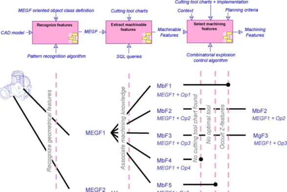
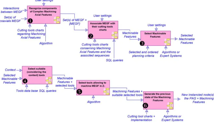
![Fig. 1. Milling plans generation concepts [12].](https://thumb-eu.123doks.com/thumbv2/123doknet/7276741.206989/3.892.141.743.104.361/fig-milling-plans-generation-concepts.webp)
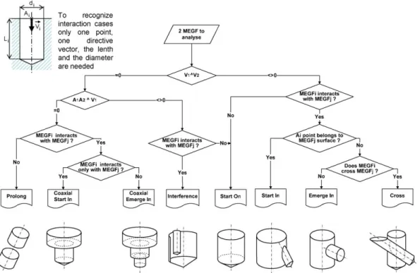
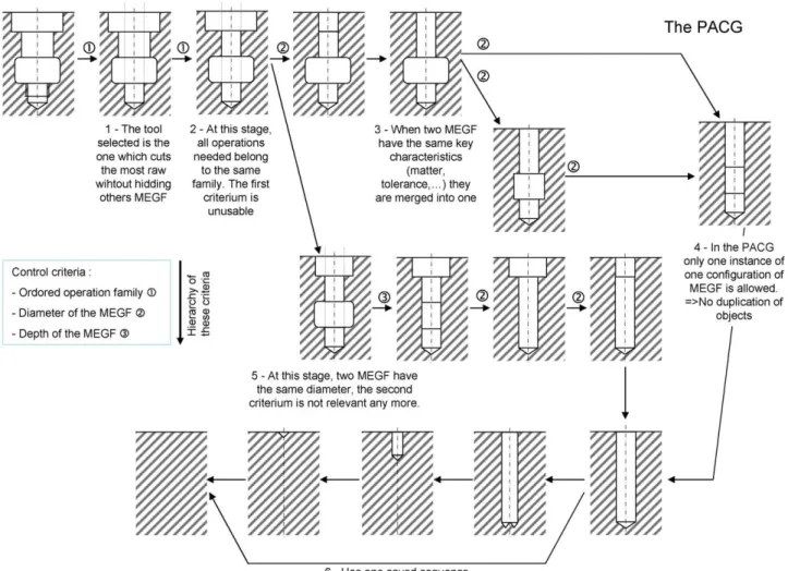
![Fig. 7. Example of one intermediate states tree [12] of the PAG.](https://thumb-eu.123doks.com/thumbv2/123doknet/7276741.206989/8.892.162.751.96.575/fig-example-intermediate-states-tree-pag.webp)
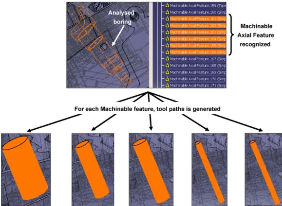
![Fig. 10. One tools chart concept example (top) [12] and its under development data base.](https://thumb-eu.123doks.com/thumbv2/123doknet/7276741.206989/11.892.210.674.93.632/fig-tools-chart-concept-example-development-data-base.webp)
Documents relatifs
A method is described for predicting acoustic feature variability by analyzing the consensus and relative entropy of phoneme posterior probability distributions
Simultaneous approximation, parametric geometry of numbers, function fields, Minkowski successive minima, Mahler duality, compound bodies, Schmidt and Summerer n–systems, Pad´
This approach consists of the following steps: (i) the set of possible candidate answers for all the input questions are retrieved by means of a search engine; (ii) each question
Inspired by his work, we propose a new and simpler algorithm to compute the fractal dimension, and design a novel and faster feature selection algorithm using correlation
En effet, dans cette approche le concepteur est forcé de définir une pièce en utilisant un ensemble de caractéristiques associées à un processus de fabrication
Also the obtained accuracies of different classifiers on the selected fea- tures obtained by proposed method are better that the obtained accuracies of the same
In this section, we explain ant system (AS) and ant colony system (ACS) in solving traveling salesman problem since we used many aspects of these approaches. We will then
One for each ocean: revision of the Bursa granularis (Röding, 1798) species complex (Gastropoda:
