HAL Id: hal-01007387
https://hal.archives-ouvertes.fr/hal-01007387
Submitted on 4 Feb 2018
HAL is a multi-disciplinary open access
archive for the deposit and dissemination of
sci-entific research documents, whether they are
pub-lished or not. The documents may come from
teaching and research institutions in France or
abroad, or from public or private research centers.
L’archive ouverte pluridisciplinaire HAL, est
destinée au dépôt et à la diffusion de documents
scientifiques de niveau recherche, publiés ou non,
émanant des établissements d’enseignement et de
recherche français ou étrangers, des laboratoires
publics ou privés.
Tolerances of joint gaps in Nd: YAG laser welded
Ti-6AI-4V alloy with the addition of filler wire
Xinjin Cao, Guillaume Debaecker, E. Poirier, Surendar Marya, Jonathan
Cuddy, A. Birur, P. Wanjara
To cite this version:
Xinjin Cao, Guillaume Debaecker, E. Poirier, Surendar Marya, Jonathan Cuddy, et al.. Tolerances of
joint gaps in Nd: YAG laser welded Ti-6AI-4V alloy with the addition of filler wire. Journal of Laser
Applications, Laser Institute of America, 2011, 23 (1), �10.2351/1.3554266�. �hal-01007387�
Tolerances of joint gaps in Nd:YAG laser welded Ti-6Al-4V alloy
with the addition of filler wire
X. Caoa兲
Aerospace Manufacturing Technology Centre, Institute for Aerospace Research, National Research Council Canada, 5145 Decelles Ave., Montreal, Quebec H3T 2B2, Canada
G. Debaecker
Ecole Centrale de Nantes, 1 Rue de la Noé, B.P. 92101, 44321 Nantes Cedex 3, France E. Poirier
Aerospace Manufacturing Technology Centre, Institute for Aerospace Research, National Research Council Canada, 5145 Decelles Ave., Montreal, Quebec H3T 2B2, Canada
S. Marya
Ecole Centrale de Nantes, 1 Rue de la Noé, B.P. 92101, 44321 Nantes Cedex 3, France J. Cuddy and A. Birur
Standard Aero Limited, 33 Allen Dyne Road, Winnipeg, Manitoba R3H 1A1, Canada P. Wanjara
Aerospace Manufacturing Technology Centre, Institute for Aerospace Research, National Research Council Canada, 5145 Decelles Ave., Montreal, Quebec H3T 2B2, Canada
The effect of joint gap on the butt joint quality of Ti-6Al-4V alloy welded using a 4 k W Nd:yttrium aluminum garnet laser
was evaluated in terms of the welding defects, microstructure, hardness, and tensile properties. The joint gap was
proportionally filled using the filler wire with the compositions of the parent alloy. Fully penetrated welds without cracking
were obtained up to a joint gap of 0.5 mm. The main defects observed in the welds were porosity and underfill. Specifically,
the porosity area increased with increasing joint gap but remained less than 1% of the fusion zone area. Large underfill defects
appeared in the weldments in the absence of a joint gap, but filler wire addition was observed to reduce this defect in the presence of a joint gap. The weld hardness decreased slightly with increasing joint gap, but the tensile properties were optimized at an intermediary gap size, probably due to the compromise between the low underfill 共after the use of a filler wire兲
and a limited amount of porosity.
Key words: laser welding, titanium alloy, joint gap, filler wire
I. INTRODUCTION
The high temperature performance, low density, biocom-patibility, and excellent corrosion-resistance of titanium and its alloys have led to a wide range of applications in demand-ing service conditions for the aerospace, automotive, medi-cal, power generation, oil and gas extraction, chemical plant, and sporting industries. Ti-6Al-4V, a workhorse grade that accounts for more than half of all the titanium tonnage in the world,1 is a two-phase ␣+ titanium alloy which contains aluminum as the alpha stabilizer and vanadium as the beta stabilizer. Due to its high strength-to-weight ratio, along with good tensile and creep properties up to a service temperature of 300 ° C, Ti-6Al-4V has been successfully used for diverse applications including 共1兲 medical, dental, and surgical de-vices;共2兲 turbine disks, compressor blades, and rings for jet engines; 共3兲 airframe and space capsule components; 共4兲
pressure vessels; 共5兲 rocket engine casings; 共6兲 helicopter rotor hubs; and共7兲 critical structural forgings.2
Conventionally, gas tungsten-arc, gas metal-arc, plasma arc welding, and electron beam welding have been used to weld titanium alloys.3–5 To date, the laser welding of Ti-6Al-4V has mainly concentrated on using CO2 lasers.
1,5–7
Limited work has been reported about the weldability of Ti-6Al-4V using high power continuous wave共CW兲 solid-state Nd:yttrium aluminum garnet共YAG兲 and fiber lasers.8,9Laser welding has many advantages including low and precise heat input, deep and narrow fusion zone共FZ兲, small heat-affected
zone 共HAZ兲, low thermal distortion, high productivity, and
good process flexibility and reliability. However, since the spot size of the laser beam and the associated molten pool are relatively small, laser welding processes in general have a low tolerance for seam gaps.10 Therefore, there is an exi-gent challenge for workshop practice to achieve precise joint preparation, workpiece clamping, and manipulator accuracy, which can reduce the cost-effectiveness of manufacturing. a兲Electronic mail: xinjin.cao@cnrc-nrc gc.ca
Clearly, an increased gap tolerance can potentially increase productivity and improve the process stability and joint qual-ity in an industrial environment.
Recently, Aalderink et al.10 compared some laser-based welding techniques for their gap bridging capabilities for 1–2-mm-thick AA5182 aluminum alloy sheets. It was found that the use of the filler wire is indispensable to increase the gap tolerance. For the single spot laser welding with the use of the cold filler wire, a gap up to 0.6 mm can be bridged as opposed to a maximum allowable gap of 0.2 mm without the use of the filler wire. However, Sun and Kuo11investigated bridging ability of CO2 laser welding for carbon and
stain-less steels. It was found that a large gap of up to 1.0 mm for 2.0-mm-thick butt joint was successfully welded with the use of a filler wire. The maximum joint gap accommodated is almost equal to the diameter of the filler wire. In spite of the inconsistency in the reported gap tolerances, as a rule of thumb, the allowable joint gap is around 10% of the work-piece thickness.11For example, a joint gap of 0.3 mm is the maximum allowable gap to produce a satisfactory joint for 3-mm-thick sheets.
To further improve the bridging capacities, laser-arc hy-brid welding process has been widely investigated. It was reported that the laser-arc hybrid welding process can bridge a gap up to 1.0 mm.10Yao et al.12even reported that laser-arc hybrid welding process is rather insensitive to a joint gap below 3 mm as long as the arc parameters are set high enough to bridge these gaps. In laser-arc hybrid welding, the filler wire is required to ignite/maintain arc and compensate for the lack of metal in a relatively large joint gap. The filler wire can be melted by partial consumption of the laser en-ergy or auxiliary electric arc, or by both.13 In the hybrid process, laser generates a deeper melt, while the arc supplies the molten filler metal to the weld pool. Although laser-arc hybrid process has been successfully implemented in ship building, transport, and construction industry,14 its applica-tion requires more elaborate tuning of multiple process pa-rameters related to arc as well as to laser.15 In addition, the laser-arc interactions can also help to stabilize the arc, par-ticularly at high welding speeds.16
Compared with the laser alone welding process, laser-arc hybrid technique demonstrated significant advantages for its gap bridging capacities. However, laser alone process is rela-tively simple and hence is still preferred for aerospace appli-cations. To date, limited work has been carried out for aero-space titanium alloys using a high power laser. In addition, a systematic investigation on the effect of the joint gap on the quality of aerospace titanium welds is still lacking. This is essential to provide practical technical guidelines for aero-space industry. To this end, the tolerance of the joint gap for 3-mm-thick Ti-6Al-4V alloy was systematically studied us-ing a 4 kW CW Nd:YAG laser with a beam size of approxi-mately 0.45 mm. The joint quality is characterized in terms of dimensions, porosity, underfill, microstructure, hardness, and tensile properties.
II. EXPERIMENTAL PROCEDURES
As-received mill-annealed grade 5 Ti-6Al-4V sheets 共AMS 4911兲 were sectioned into coupons with dimensions of
the roughly 102 mm in length⫻63 mm in width ⫻3.05 mm in thickness. Laser welding was performed along the specimen length, which was perpendicular to the rolling direction of the sheet material. The faying and adja-cent surfaces of each specimen were brushed and then cleaned with ethanol to remove any contaminants prior to fixturing. The welding equipment consisted of a 4 kW CW solid-state Nd:YAG laser system equipped with an ABB ro-bot and a magnetic holding fixture. A collimation lens of 200 mm, a focal lens of 150 mm, and a fiber diameter of 0.6 mm were employed to produce a laser beam with a focusing spot diameter of approximately 0.45 mm and a Rayleigh length of 2.34 mm. Since titanium is highly reactive with atmospheric elements, especially in the liquid state and at high tempera-tures, adequate measures were taken to shield the fusion zone and the heated surfaces until these regions were cooled be-low 100 ° C. In this work, high purity argon at a fbe-low rate of 23.6 l/min共50 cfh兲 was used to shield the top surface of the workpieces. The shielding of the root and the trailing gas shield on the top surface were performed using helium at a total flow rate of 66.1 l/min共140 cfh兲. All experiments were carried out at a laser power of 4.0 kW, a defocusing distance
of ⫺1 mm 共i.e., 1 mm below the sheet top surface兲 and a
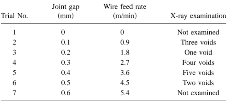
welding speed of 3.0 m/min. The joint gap used was varied from 0共no gap兲 to 0.6 mm 共TableI兲. A Ti-6Al-4V filler wire
共AMS 4956A ELI兲 with a nominal diameter of 1.14 mm was fed at a fixed angle of 30° toward the top surface of the workpiece. It is noteworthy that the filler wire was usually impinged by the laser beam on the top surface of the work-piece. The feed rate of the filler wire was calculated by using the volume flow rate constancy equation
Wire feed rate =Welding speed⫻ Gap area Filler wire area .
Selected joints were then examined for defects using x-rays. The surface quality of the laser welds was visually evaluated in the as-welded condition. Three transverse sections were cut from each weld to examine the weld integrity and micro-structure using optical microscopy. After sectioning, the specimens were mounted using cold-setting resin, ground and polished using automated techniques to produce a mir-rorlike finish. Etching of specimens was performed by im-mersion in Kroll’s reagent 共1–3 ml HF+2–6 ml HNO3
+ 100 ml H2O兲 for 10–25 s. Microstructural examination was carried out using an inverted optical microscope
共Olym-TABLE I. Welding processing parameters used.a
Trial No.
Joint gap 共mm兲
Wire feed rate
共m/min兲 X-ray examination
1 0 0 Not examined 2 0.1 0.9 Three voids 3 0.2 1.8 One void 4 0.3 2.7 Four voids 5 0.4 3.6 Five voids 6 0.5 4.5 Two voids 7 0.6 5.4 Not examined a
Note: Pore size ranges from 0.25 to 0.5 mm.
pus GX710兲, equipped with a digital camera andANALYSIS FIVE image analysis software for measurement of the joint geometry. The microstructure was also observed for selected specimens using a Hitachi S-3600N scanning electron micro-scope共SEM兲 with an EDAX Genesis energy dispersive x-ray spectroscopy 共EDS兲 system. The Vickers microindentation hardness was performed using a Struers Duramin A-300 hardness tester at a load of 500 g, a dwell period of 15 s, and an interval of 0.2 mm. Also for each joint, four subsize ten-sile specimens were machined according to ASTM E8M-01 to give gauge dimensions of 6.0 mm in width, 32 mm in parallel length, and 125 mm in overall length. The specimens were tested at room temperature using a 50 kN Instron ma-chine, a 2620-604 Instron extensometer共gauge length of 25 mm used兲, and a crosshead speed of 2 mm/min.
III. RESULTS AND DISCUSSION A. Joint geometry
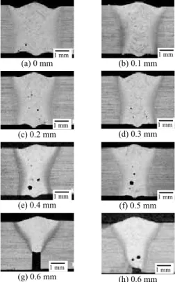
Visual inspection of the welds revealed a silver metallic surface indicating that good shielding during welding was achieved. Figure 1 shows the overview of the transverse sections obtained at various joint gaps. It can be seen that the welds are fully penetrated for joint gap values up to 0.5 mm, i.e., the maximum gap tolerance was determined to be 0.5 mm, roughly equivalent to the beam size used. At 0.6 mm, a lack-of-penetration defect appears. The different areas, i.e., FZ, HAZ, and base metal 共BM兲, can be clearly distinguished due to the microstructural differences across the welds.
As shown in Fig.2, the area and width of the FZ共top, middle, and bottom兲 decrease with increasing joint gap. This decrease is more prominent at a small joint gap and then
becomes relatively smooth above a gap size of 0.2 mm. It is noteworthy that in Fig.2the values at a joint gap of 0.6 mm are not taken into account due to the lack-of-penetration defect for this condition. In this latter case, a zero root width is assumed. Similarly, the HAZ area and width also decrease with increasing joint gap. For the middle HAZ width, there is an erratic value at a gap of 0.6 mm. This is due to the formation of the lack-of-penetration defect. In this case, the entire molten metal is located on the upper part of the weld, and the width is therefore increased 关Figs.1共g兲and1共h兲兴.
The overall decrease in the dimensions of the FZ and HAZ at higher joint gap values is directly linked to the increase in the gap size. The laser beam was set to be aligned with the joint in between the two workpieces to be butt welded. Hence, in the presence of a gap 共between 0.1 and 0.6 mm in this work兲, part of the laser beam can be
(a) 0 mm (b) 0.1 mm (c) 0.2 mm (d) 0.3 mm (e) 0.4 mm (f) 0.5 mm (g) 0.6 mm (h) 0.6 mm 1 mm 1 mm 1 mm 1 mm 1 mm 1 mm 1 mm 1 mm
FIG. 1. Overview of weld cross sections at various gaps.
(a) (b) (c) 0 2 4 6 8 10 0,0 0,2 0,4 0,6 Joint gap (mm) A re a (mm² ) HAZ FZ 0 1 2 3 4 5 0,0 0,2 0,4 0,6 Joint gap (mm) Fus ion z one w idt h (m m ) Top Middle Root 0,0 0,5 1,0 1,5 0,0 0,2 0,4 0,6 Joint gap (mm) H A Z mi d -w id th (mm) LOP
FIG. 2. Effect of gap on FZ and HAZ area and width.
directly lost through the gap. In addition, laser energy may be lost due to the reflection caused by the filler wire surface. These losses of the laser energy increase obviously with increasing joint spacing and wire feed rate. Less effective energy available for welding leads to smaller FZ and HAZ. In addition, significant variations in the penetration depth are observed at a joint gap of 0.6 mm indicating the instability of laser energy absorption at a large joint gap关Figs.1共g兲and 1共h兲兴.
As shown in Figs. 3共a兲 and 3共c兲, the joint gap has no clear influence on the weld reinforcement area and height. Generally speaking, the reinforcement height remains relatively low, 0.2–0.25 mm 共less than 10% of the sheet thickness兲, for most of the fully penetrated joints and meets the acceptance criteria stipulated in AWSD17.
B. Welding defects
As shown in Fig. 1, no cracks are observed in the weldment, but porosity frequently appeared in the FZ. This was further confirmed by X-ray examination and analysis as indicated in TableI. In this study, the minimum dimensions that can be detected by X-ray were approximately 0.025 mm for the porosity and 0.025⫻0.127 mm2 for linear indications 共cracks, lack of fusion, etc.兲. In addition, underfill defects are visible on both the crown and root sides of the welds, as shown in Fig. 1. However as indicated in Fig.3共b兲, the overall underfill depth for gap sizes from 0.1 to 0.5 mm is less than 0.12 for the fully penetrated joints and meets the acceptance criteria stipulated in AWSD17.
C. Underfill defects
Large underfill defects are observed on both the crown and root sides of the welds in the absence of a joint gap. As is well known, underfill defects can weaken welds. For example, underfilling can reduce the sheet thickness and create stress concentration that will significantly reduce the tensile and fatigue strengths of the joints. Underfill defects, therefore, must be minimized. Specifically, the area and depth of the underfill defect on both the crown and root sides of the welds were measured as given in Fig. 3. It can be noticed that the average or maximum underfill depth appears at zero joint gap, namely, without the use of a filler wire. Compared with the zero joint gap, the average or maximum underfill depth is approximately halved at gap values from 0.1 to 0.5 mm. This trend is further intensified for the underfill area. The total underfill area including that on both the top and bottom sides obtained with zero gap was approximately five times greater than that at gap sizes from 0.1 to 0.5 mm. Therefore, the application of filler wire can increase the gap tolerance, reduce the underfill defects, and improve the process stability while saving both preparation time and costs for welding.
At zero joint gap, the overall underfill area is almost five times the reinforcement area indicating a significant loss of the molten metal, probably due to a combination of molten metal spattering and evaporation. When a filler metal was used, the loss of molten metal was significantly decreased. The measurement of the alloy chemistry using EDS with a SEM indicated a composition of 6.4 wt % Al and 3.0 wt % V for the base metal and 6.5 wt % Al and 2.6 wt % V for the FZ, which suggests that the evaporative losses from the molten weld pool are minor during laser welding. However, the reinforcement area was greater than the underfill area, at joint gaps from 0.1 to 0.5 mm 关Fig. 3共a兲兴, which may be related to combined effects of thermal expansion and phase transformation.
D. Porosity defects
In addition to the underfill defects discussed above, porosity is another main defect that was frequently observed, as shown in Fig.1. Most of the porosity is nearly spherical in shapes but some are elongated. The pores can appear at various locations, depending on their origin. They are
0.0 0.1 0.2 0.3 0.0 0.2 0.4 0.6 Joint gap (mm) Ar e a (mm ²) Underfil area Reinforcement area (a) 0,0 0,1 0,2 0,3 0,0 0,2 0,4 0,6 Joint gap (mm) U nde rf ill de pt h (m m
) Max. underfill depthAverage underfill depth
(b) 0,0 0,1 0,2 0,3 0,4 0,5 0,0 0,2 0,4 0,6 Joint gap (mm) R ei n fo rcem en t h ei g h t (m m ) Average height Max. height (c)
FIG. 3. Effect of joint gap on underfill and reinforcement area and size.
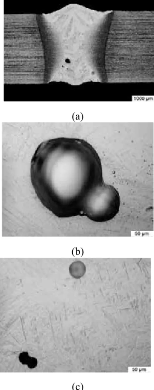
mainly located at 共i兲 the lower part of the FZ in the lack-of-penetration weld 关Fig. 1共h兲兴, 共ii兲 near the HAZ/FZ interfaces 共Fig.4兲, and 共iii兲 centerline grain boundary 共Fig.
5兲 and randomly distributed in the FZ 共Fig. 6兲. It is well
known that in laser welds the porosity can be formed due to the evolution of dissolved gas, collapse of unstable keyhole, entrapment of gases by surface turbulence, metal evaporation, and solidification shrinkage.17
In titanium welds shielded by inert gas, hydrogen is the main source for gas porosity.18Figure7shows the solubility curve for hydrogen in titanium as a function of temperature at 1 atm external pressure.19 The solubility of hydrogen in both solid and liquid titanium decreases with increasing temperature. The effect of temperature and pressure on solubility of hydrogen in liquid titanium can be represented by the following equation:19
log S = 2370/T + 0.626 + 0.5 log PH2,
where S is the solubility of hydrogen in liquid titanium
共ml/100 g兲, T is the liquid temperature 共Kelvin兲, and PH2is
the equilibrium pressure of hydrogen above the surface of liquid titanium 共mm Hg兲. It is clear that with an increase in the temperature of the weld pool and a decrease in the partial pressure, the solubility of hydrogen in liquid
titanium decreases. At the melting point, however, liquid titanium has a higher solubility for hydrogen than solid titanium.19,20 Therefore, hydrogen will precipitate at the liquid/solid interface during solidification. The decrease in solubility of hydrogen at the freezing point indicates that the gas porosity can be formed under certain conditions. As is well known, the occurrence of gas porosity comprises three stages, namely, nucleation, growth, and escape.
The nucleation of bubbles requires creation of a gas-liquid interface, causing an increase in the free energy of the system. There are two mechanisms for nucleation, i.e., homogeneous and heterogeneous. In homogeneous nucleation, the pores form without the help of the discontinuous substrates. A pressure, as high as 50 000 atm,
(a)
(b)
FIG. 4. Porosity near HAZ/FZ interfaces.
FIG. 5. Porosity at centerline grain boundary.
(a)
(b)
FIG. 6. Porosity randomly distributed in the fusion zone.
FIG. 7. Solubility curve for hydrogen in titanium as a function of tempera-ture at 1 atm external pressure共Ref.19兲.
is required to fracture the liquid titanium,21 and hence homogeneous nucleation is unlikely a feasible mechanism for hydrogen pore formation in titanium and its alloys. In contrast, heterogeneous nucleation is much more favored. In the presence of discontinuities such as nonwetted solid inclusions, hydrogen can directly diffuse from hydrogen-supersaturated regions into the discontinuous sites. In this case, bubbles can directly grow with no nucleation.
In titanium welds shielded by inert gas, hydrogen is the main source for gas porosity.18Heating during welding gives a decrease in the solubility of hydrogen in liquid titanium with increasing temperature. The evolved hydrogen can form porosity by nucleation or direct diffusion into discontinuities or existing pores. Also, the pores can expand if they are heated to higher temperatures. In laser welding, the molten pool exists for only a short time due to the high welding speed and rapid cooling rate. Therefore, the gas porosity does not grow greatly in volume. Due to the low density, the bubbles formed in the liquid metal can float up. The driving force for the escape of bubbles is the reduction in interfacial energy and free energy of the system. Low viscosity, high fluidity, and low hydrostatic pressure of the liquid head will favor the flotation of the bubbles. During the rise, some small pores may meet and coalesce to form a large pore, causing a net increase in total pore volume due to both coalescence and reduction of surface tension pressure.21 Figure 8 shows some floating bubbles which are at the critical condition to coalesce during their rise.
Bubble rising and degassing may take place throughout the entire period of molten pool existence. The escape to the atmosphere is limited by the vapor pressure and diffusion rate, so that the metal may be “supersaturated” with hydrogen. If the bubbles cannot escape out of the surface of the weld pool, gas pores will form. Therefore, gas bubbles in titanium welds can form during the heating and melting stages of the metal共not only in the solidification stage兲.
At high heat inputs, both the temperature and the time at this temperature increase. The temperatures of the molten metal will be higher, and hence the lifetime of liquid pool would be longer. The solubility of hydrogen in titanium will thus be lower at higher temperatures共Fig.7兲. In addition, the liquid has a lower viscosity and a higher fluidity at higher temperatures. At high heat input, therefore, the weld pool is relatively supersaturated with hydrogen and is favorable for the nucleation, growth, and escape of the bubbles. In a typical molten pool, the temperatures are highest in the keyhole and usually decrease from the evaporation temperatures at the keyhole to the melting point toward the fusion boundary.19 Therefore, the solubility of hydrogen is more supersaturated at the weld center than the fusion boundary. The weld center also remains at a temperature above the solidus for a longer period of time than the fusion periphery. The lower viscosity and higher fluidity in the weld center will favor the diffusion of hydrogen from the hot center to the cold fusion boundary. Therefore, bubbles tend to migrate from the weld center to the fusion boundary, explaining the presence of porosity near the fusion boundary as shown in Fig.4. In this case, less porosity should appear at the weld center. In this work, however, porosity is still
observed in the weld center as shown in Fig. 5. During solidification, the dissolved hydrogen is rejected from the liquid and appears at the solid/liquid interface. With the growth of columnar grains from the partially melted zone, the impurities and hydrogen will be richer in the remaining liquid. The center zone will be the last region of the weld to solidify and thus is usually enriched with hydrogen. In addition, the hydrogen-rich liquid in the center region has a low temperature at the late stage of solidification, and hence the gas cannot effectively escape, explaining the porosity in centerline grain boundaries. Therefore, the appearance of the centerline porosity indicates that the welds are heavily contaminated by hydrogen, which may come from the original titanium alloys, or pick up during welding. During the rapid cooling of the laser welds, some gas porosity may distribute randomly in the FZ, probably due to the energetic convective movement.
In addition to the hydrogen porosity, the collapse of unstable keyholes is usually considered to be another main
(a)
(b)
(c)
FIG. 8. Coalescence of porosity obtained at joint gaps of共a兲,共b兲 0.1 and 共c兲 0.2 mm.
mechanism for the formation of porosity in laser welds.17 Keyhole stability during laser welding depends on a high degree on the balance of forces active inside the keyhole. Upon the establishment of the vapor cavity, the fluid forces of the molten pool are balanced by the vaporization pressure within the cavity. The inherent instability of keyholes may lead to periodic collapse of the liquid metal surrounding the vapor cavity causing the formation of periodic voids. Pastor
et al.22 schematically explained the mechanism for the formation of the porosity caused by the collapse of unstable keyholes. The pores caused by unstable keyholes are usually located at the lower half of the welds or at the weld root along the keyhole path. The essential point in reducing this porosity is to keep the keyhole stable, but it is only achievable in high speed welding. In this work, a welding speed of 3 m/min was used, and the collapse of unstable keyhole does not seem to be the main mechanism for the formation of porosity. In addition, interdendritic shrinkage porosity can form as shown in Fig. 9. Other possible mechanisms for porosity formation include entrapment of gases by surface turbulence, and metal evaporation.17 However, these are not main mechanisms as demonstrated in this work. The porosity in laser welded titanium joints is mainly due to hydrogen.
During solidification, the pore will shrink with the reduction in the temperature of the liquid metal. The shrinking continues until the solidus temperature is reached. Any further decrease in temperature can only slightly reduce the pore sizes in the solid state.
For each sample, the size and area of the porosity were measured in order to check their evolution with joint gap. As shown in Fig.10, the porosity area increases with increasing
joint gap for the fully penetrated welds. The percentage ratio of the porosity area to the FZ area also increases with increasing joint gap. It is noted that there is only a slight increase in the porosity area at small gaps but a large increase at large gaps. The increase in porosity comes particularly from the fact that more filler wires were used at higher joint gaps. The filler wire surface can absorb some moisture and is hard to clean, thereby producing more porosity. The presence of the joint gap itself is a source of defect generation. It should be noted that the porosity percentage to the FZ area remains well below 1%, which is low even at the maximum joint gap used in this work. In spite of the low porosity level, the presence of porosity can weaken the welds, particularly when several gas bubbles are merged together to form larger pores. This may happen more often in the centerline grain boundary 共Fig. 5兲. In some extreme cases, the pores can be agglomerated and create a long porosity in the center of the welds.
E. Microstructure
The different regions of the weld macrostructure can be correlated with the maximum temperature reached in the material.23 Figure11 displays typical microstructures of the base metal and FZ in a weld. As indicated in Fig.11共a兲, the base metal is composed of dark  phase regions in the dominating bright ␣matrix, a typical annealed structure for the ␣−titanium alloy. In the SEM image 关Fig.11共b兲兴, the
phase appears to be bright 共due to V兲 and is distributed at the boundaries of the elongated␣grains共dark due to Al兲.
The FZ is defined as the region where the temperature exceeds the alloy’s effective liquidus temperature. As shown in Figs.11共c兲and11共d兲, the FZ consists mainly of acicular martensite 共␣
⬘
兲. It was reported that cooling rates higher than 410 ° C/s are usually required for Ti-6Al-4V alloy to attain a completely martensitic microstructure.24 The high self-quench rate associated with the laser beam welding process certainly promotes the diffusionless transformation of thephase into a martensitic structure. The boundaries of the prior  grains were clearly revealed in the FZ 共Figs.5and6兲. As shown in Fig.11共c兲, the␣phase forms atgrain
boundaries indicating that the cooling rate is close to the lower limit of the ␣
⬘
transformation window. The small FZ exhibits coarse columnar  grains which grow opposite to the heat flow direction. These coarse grains have epitaxially grown on the semimelted  grains in the partially melted zone, i.e., atoms are just added to the substrate and neither activation energy nor undercooling is required. Then these prior  grains undergo martensitic transformation upon cooling.Within the HAZ, Ti-6Al-4V displays two regions, distinguished by the-transus temperature T共⬃985 °C兲.23 The HAZ close to the FZ共near HAZ兲 is approximately the region where the maximum temperature is greater than T and less than liquidus, while the HAZ adjacent to the base metal 共far HAZ兲 is at a temperature lower than T and greater than a minimum temperature required for microstructural change. This minimum temperature is difficult to define, as it depends on transformation kinetics.23
FIG. 9. Gas and shrinkage porosity.
0,0 0,2 0,4 0,6 0,8 1,0 0,0 0,2 0,4 0,6 Joint gap (mm) P o ro si ty ar ea (% ) 0,00 0,02 0,04 0,06 0,08 0,10 Po ro s it y ar ea (mm 2)
Porosity area/FZ area Porosity area
FIG. 10. Effect of joint gap on porosity area and percentage.
Therefore, the near HAZ has a quenched structure. The far HAZ is a mixture of primary␣andphases with␣
⬘
, which correspond to a structure quenched below the -transus. Although the HAZ is very narrow, a significant variation in the microstructure is apparent.In this study, the filler wire used has the same chemistry as the base metal. Therefore, the essential nature of the microstructures in different weld zones does not seem to be
affected by the gap size. In fact, the phases formed depend essentially on the cooling rates experienced, and for the acceptable gaps that were well filled, little differences in microscopic structures were observed over the joint gaps from 0 to 0.5 mm in this work.
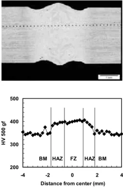
200 300 400 500
-4 -2 0 2 4
Distance from center (mm)
H V 500 g f FZ HAZ HAZ BM BM
FIG. 12. Vickers hardness in the weld with zero gap.
200 300 400 500
-4 -2 0 2 4
Distance from weld center (mm)
H V 500 g f Top Middle Bottom
FIG. 13. Vickers hardness at a joint gap of 0.3 mm.
.
(a) Base metal (OM)
(b) Base metal (SEM)
(c) Fusion zone (OM)
(d) Fusion zone (SEM)
FIG. 11. Typical microstructures.
F. Hardness
Figures 12 and 13 show the distribution of Vickers hardness. For all joint gaps from 0 to 0.6 mm, the hardness profiles are similar. The lowest hardness is obtained in the base metal, and then it increases from the HAZ to the FZ. The maximum value was obtained in the FZ due to the formation of much harder␣
⬘
. As shown in Fig.13, there is a valley of hardness in the center of the FZ which is probably due to the lower cooling rate in this region. Compared to the profile across the middle of the weld, the hardness values near the top and bottom surfaces are more uniformly distributed. In the near HAZ, the quenched structure produced a similar hardness to that in the FZ. In the far HAZ, there is a mixture of␣⬘
and primary␣ and phases. Near the FZ side, the proportion of␣⬘
is close to 100% with very little ␣+. On the contrary, near the border between the far HAZ and the base metal, the majority of the microstructure consists of␣+with a very small amount of␣
⬘
. Between these two borders, the proportions vary depending on the distance to each zone. Therefore, the narrow HAZ has significant heterogeneity in both microstructure and mechanical properties. Figure 14 shows the variations in the average hardness in the FZ with increasing joint gap. It can be noticed that there is a slight decrease in hardness with increasing joint gap, probably due to small prior  grain sizes. The average hardness is approximately 342 HV for base metal and 387 HV for the FZ.G. Tensile properties
Figure 15 shows the variation in the tensile properties with increasing joint gap. The base metal has a tensile strength of 1062 MPa, a yield strength of 996 MPa, and an elongation at break of 14%共obtained over a gauge length of 50 mm兲. In this work, subsize specimens were used, and thus only the joint strength can be compared with that of the base metal. The tensile strength is similar to the base metal with joint efficiencies ranging from 86% to 101%.
It was reported that a low ductility in weld FZ and near HAZ significantly limits the use of welded titanium structures.3The poor ductility results in part from the coarse prior- grain size and the preferential crack propagation along the prior-grain boundaries. In laser welds, relatively small prior- grain sizes can be obtained due to the rapid cooling rate. The poor elongation obtained at zero joint gap is probably due to the underfill defects that create a stress concentration 共significant reduction in the joint transverse section兲. The use of a filler wire can decrease the underfill defect, and thus relatively high ductility can be obtained.
TableIIshows the failure location of the tensile samples at various joint gaps. This information added to the previous measurements indicates the evolution of the tensile behavior. Logically, tensile characteristics 共especially elongation兲 are higher when the break occurs in the base metal 共at gaps of 0.2–0.3 mm兲 and lower when the break happens in the FZ. The tensile failure happens in the most fragile location. If the weld is weaker than the base metal, it is in the FZ where the rupture occurs. If the weld is stronger than the base metal, the latter will fail first.
The best results are for joint gap values of 0.2 and 0.3 mm, beyond which the results deteriorate again. On this basis it can be said that the increase of porosity in the FZ weakens the joint. For joint gaps of 0.2 and 0.3 mm, the porosity is low and the reduction of the underfill through the addition of filler wire optimizes the process. For a joint gap greater than 0.3 mm, the number of pores increases rapidly and the tensile properties are reduced. The values obtained at joint gaps of 0.4 and 0.5 mm are to be taken with caution because the results may also be influenced by other factors such as contamination of oxygen, which was not taken into account in this study. Therefore, the best joint gap for laser welding of Ti-6Al-4V is approximately 10% of the material thickness, but the maximum gap tolerance was determined to be 0.5 mm, roughly equivalent to the spot size used.
TABLE II. Failure locations after tensile testing.
Joint gap 共mm兲 Failure location 0 4 FZ 0.2 4 BM 0.3 4 BM 0.4 1 BM+ 3 FZ 0.5 2 BM+ 3 FZ 0.6 0 400 800 1200 0.0 0.2 0.4 0.6 Joint gap (mm) S tr e ngt h (MP a ) 0 5 10 15 20 El o n g at io n (% ) YS UTS El
FIG. 15. Effect of joint gap on tensile properties.
300 350 400 450 500 0.0 0.2 0.4 0.6 Joint gap (mm) H ar d n ess (H V 500 g f) BM
FIG. 14. Effect of joint gap on fusion zone hardness.
IV. CONCLUSIONS
共1兲 When the filler wire with the compositions of the parent alloy is used, the butt joints can be welded with a full penetration up to a joint gap of 0.5 mm, roughly equiva-lent to the spot size used.
共2兲 The dimensions of the fusion and heat-affected zones are reduced with increasing joint gap.
共3兲 No cracks were detected in the laser welds. The main defects observed are underfill and gas porosity. The pore area increases with increasing joint gap but remains less than 1% of the FZ area. The underfill defect is more prominent in the absence of a joint gap, and the use of a filler wire can significantly reduce this defect.
共4兲 The hardness of the welds is slightly decreased with increasing joint gap. The welds have good resistance for all gap sizes with a joint efficiency ranging from 86% to 101%. But the optimal tensile properties are obtained at an intermediary joint gap 共0.2–0.3 mm兲, approximately 10% of the material thickness, which provides a balance between the low underfill, due to the use of a filler wire, and a limited amount of porosity.
ACKNOWLEDGMENTS
Thanks are due to B. Marius for the technical support provided during tensile property testing.
1
G. Casalino, F. Curcio, and F. M. C. Minutolo, “Investigation on Ti-6Al-4V laser welding using statistical and Taguchi approaches,”J. Mater.
Process. Technol. 167, 422–428共2005兲.
2
“Technical data sheet: Allvac titanium 6Al-4V alloy,” http:// www.allvac.com.
3
W. A. Baeslack III, D. W. Becker, and F. H. Froes, “Advances in titanium alloy welding metallurgy,” J. Met. 5, 46–58共1984兲.
4
L. W. Tsay and C. Y. Tsay, “The effect of microstructures on the fatigue crack growth in Ti-6Al-4V laser welds,” Int. J. Fatigue 19, 713–720
共1997兲.
5
Z. Sun, D. Pan, and W. Zhang, Proceedings of the 6th International Con-ference: Trends in Welding Research, Pine Mountain, GA, 2002 共unpub-lished兲, pp. 760–767.
6
F. Caiazzo, F. Curcio, G. Daurelio, and F. M. C. Minutolo, “Ti-6Al-4V sheets lap and butt joints carried out by CO2laser: Mechanical and
mor-phological characterization,” J. Mater. Process. Technol. 149, 546–552
共2004兲.
7
F. Memola, C. Minutolo, F. Curcio, G. Daurelio, and F. Caiazzo,
Proceed-ings of XV International Symposium on Gas Flow, Chemical Lasers, and High-Power Lasers, Bellingham, WA, 2005, edited by J. Kodymova 共un-published兲, pp. 907–912.
8
X. Cao and M. Jahazi, “Effect of welding speed on butt joint quality of Ti-6Al-4V alloy welded using a high power Nd:YAG laser,”Opt. Lasers
Eng. 47, 1231–1241共2009兲.
9
X. Cao, G. Debaecker, M. Jahazi, S. Marya, J. Cuddy, and A. Birur, “Effect of post-weld heat treatment on Nd:YAG laser welded Ti-6Al-4V alloy quality,”Mater. Sci. Forum 638–642, 3655–3660共2010兲. 10
B. J. Aalderink, B. Pathirajand, and R. G. K. M. Aarts, “Seam gap bridg-ing of laser based processes for the weldbridg-ing of aluminum sheets for in-dustrial applications,”Int. J. Adv. Manuf. Technol. 48, 143–154共2010兲. 11
Z. Sun and M. Kuo, “Bridging the joint gap with wire feed laser weld-ing,”J. Mater. Process. Technol. 87, 213–222共1999兲.
12
Y. Yao, M. Wouters, K. Nilsson, and A. F. H. Kaplan, “Influence of joint geometry and fit-up gaps on hybrid laser-metal active gas共MAG兲 weld-ing,”J. Laser Appl. 18, 283–288共2006兲.
13
J. K. Kristensen, D. Petring, and S. Webster, Proceedings of the 63rd Annual Assembly & International Conference of International Institute of Welding, AWST-10/101, July 2010共unpublished兲, pp. 507–515.
14
S. Keitel, U. Jsanu, and J. Neubert, Fourth International Symposium on High Power Lasers and Their Applications, St. Petersburg, Russia, 24–26 June 2008共unpublished兲.
15
S. Katayama, Hybrid-Laser Arc Welding, edited by O. O. Flemming 共Woodhead, Cambridge, UK, 2009兲, pp. 28–46.
16
P. E. Denney, B. W. Shinn, and P. M. Fallara, Proceedings of the 15th
International Offshore and Polar Engineering Conference, Seoul, Korea,
19–24 June 2005共The International Society of Offshore and Polar Engi-neers, CA, 2005兲, p. 106.
17
X. Cao, M. Jahazi, J. P. Immarigeon, and W. Wallace, “A review of laser welding techniques for magnesium alloys,”J. Mater. Process. Technol.
171, 188–204共2006兲.
18
G. L. Petrov and A. N. Khatuntsev, “The role of chemical reactions in the formation of pores in the welding of titanium alloys,” Svar. Proiz. 8, 81–84共1975兲.
19
T. Mohandas, D. Banerjee, and V. V. Kutumba Rao, “Fusion zone micro-structure and porosity in electron beam welds of an␣+titanium alloy,” Metall. Mater. Trans. A 30A, 789–798共1999兲.
20
D. R. Mitchell, “Porosity in titanium welds,” Welding Supplement 4, 157s–167s共1965兲.
21
F. Karimzadeh, M. Salehi, A. Saatchi, and M. Meratian, “Effect of mi-croplasma arc welding process parameters on grain growth and porosity distribution of thin sheet Ti6Al4V alloy weldment,”Mater. Manuf.
Pro-cesses 20, 205–219共2005兲.
22
M. Pastor, H. Zhao, and T. DebRoy, “Pore formation during continuous wave Nd:YAG laser welding of aluminum for automotive applications,”
Revista de Metalurgia36, 108–117共2000兲.
23
A. B. Short, “Gas tungsten arc welding of␣+ titanium alloys: A re-view,”Mater. Sci. Technol. 25, 309–324共2009兲.
24
T. Ahmed and H. J. Rack, “Phase transformation during cooling in␣ +titanium alloys,”Mater. Sci. Eng., A 243, 206–211共1998兲.