HAL Id: hal-00992666
https://hal.archives-ouvertes.fr/hal-00992666
Submitted on 19 Sep 2014HAL is a multi-disciplinary open access
archive for the deposit and dissemination of sci-entific research documents, whether they are pub-lished or not. The documents may come from teaching and research institutions in France or abroad, or from public or private research centers.
L’archive ouverte pluridisciplinaire HAL, est destinée au dépôt et à la diffusion de documents scientifiques de niveau recherche, publiés ou non, émanant des établissements d’enseignement et de recherche français ou étrangers, des laboratoires publics ou privés.
OFDM PLC transmission for aircraft flight control
system
Thomas Larhzaoui, Fabienne Nouvel, Jean-Yves Baudais, Pierre Degauque,
Virginie Degardin
To cite this version:
Thomas Larhzaoui, Fabienne Nouvel, Jean-Yves Baudais, Pierre Degauque, Virginie Degardin. OFDM PLC transmission for aircraft flight control system. 18th IEEE International Symposium on Power Line Communications and its Applications, ISPLC 2014, 2014, Glasgow, Scotland, United Kingdom. pp.220-225, �10.1109/ISPLC.2014.6812333�. �hal-00992666�
OFDM PLC Transmission for Aircraft Flight Control
System
Thomas Larhzaoui, Fabienne Nouvel, Jean-Yves Baudais IETR
Rennes, France
[email protected], [email protected], [email protected]
Pierre Degauque, Virgine Dégardin IEMN
Lille, France
[email protected], [email protected]
Abstract— In the new civil aircrafts, hydraulic flight
control systems are being replaced by electrically powered controls. The main interests are a better flexibility and a decrease in maintenance costs. Though the electrical wiring will replace the hydraulic tubing, it is essential to limit as much as possible the amount of electrical wiring. In order to decrease the total wires length, it is proposed to use power line communications (PLC) technology for data transmission over a high voltage direct current (HVDC) network for flight control system (FCS). However, PLC for safety-critical avionic systems are rarely studied. This paper is the first step of a PLC physical layer development for aircraft FCS. In this paper, a parametric study for an OFDM PLC transmission between the control unit and the electrically powered actuators for FCS is developed.
This study takes into account the channel
characteristics, the electromagnetic compatibility, the hardware and the aeronautical constraints. The purpose is to define the frequency transmission bandwidth, the number of subcarriers and the maximum constellation size for the OFDM transmission.
Keywords- PLC; OFDM; Bit rate; real time constraints; aeronautics, critical systems, flight control systems
I. INTRODUCTION
To improve the flexibility of the aircrafts, and to reduce construction and possession costs, the hydraulic and pneumatic energy networks will be reduced in favor of electrical networks. However, these changes have an important impact on the wiring length. To decrease the number of wires, it is proposed to use power line communication (PLC) for flight control system (FCS). PLC technology allows using power wires for the transmission of control and monitoring. In addition, to simplify the electrical control network, it is possible to check the
integrity of power wires, for example by telemetry, which improves the availability of the FCS.
PLC technology has proven its reliability in the indoor networks with the Homeplug Av standard [1]. It provides a bit rate about 200 Mbit/s in the [1;30] MHz bandwidth with orthogonal frequency division multiplexing (OFDM) transmission technique. Today, several studies show the opportunity of PLC to be used for embedded systems like cars [2-5], boats [7,8], and trains [9,10]. Concerning aeronautic systems, [11,12] proposed to use PLC over the cabin lighting system network for multimedia applications. However, even if the cabin lighting system network is representative of one part of the aircraft electrical networks, it is not appropriate for safety-critical systems like FCS.
A first study, which proposed to use PLC for critical system, has been done in [13]. The purpose is to use PLC technology for driving an electrical actuator for landing gear between the power inverter and the actuator. However, the wires length between the power inverter and the actuator is about five meters, and the network is a non-filtered AC network. It would be more interesting to use PLC on a longer network. Today, a new power network, the high voltage direct current (HVDC), replaces the AC network. It is filtered and is about thirty meters long. Thus, in this paper, it is proposed to use PLC from the control unit to the power inverter on the HVDC power network, as described by Fig. 1. In addition, no standard is defined for PLC in aircrafts. Therefore, this paper constitutes the first step of a PLC physical layer development for aircraft FCS.
Currently, the FCS does not need high bit rate, about 1 Mbit/s, but a bit rate of 10 Mbit/s is more realistic for the future FCS. In addition, data transmission must comply with both real time constraints and the electromagnetic compatibility tests specified in the DO-160 [14]. In this paper, two topologies are considered. The first one, the point-to-point topology, is presented in Fig. 1. It is composed of one PLC master modem, which transmits data to one PLC slave modem. The second one, the
point-to-multipoint architecture, is composed of one PLC master modem which transmits data to two PLC slave modems.
Spoiler PLC Master Calculator Unit Power Inverter Actuator Spoiler Spoiler Spoiler Spoiler Aileron Filter Control signal HVDC network ±270 V AC Network 115 V Filter Breaker From/to AFDX avionics bay HVDCRN ±270 V PLC Slave Spoiler PLC Master Calculator Unit Power Inverter Actuator Spoiler Spoiler Spoiler Spoiler Aileron Filter Control signal HVDC network ±270 V AC Network 115 V Filter Filter Breaker From/to AFDX avionics bay HVDCRN ±270 V PLC Slave PLC Slave
Figure 1. PLC system for point-to-point architecture Concerning the connections between the power wires and the transmission systems, two kinds of couplers are used: capacitive couplers and inductive couplers. OFDM technic, which has been used with success in several telecommunication systems like DVB, indoor PLC, 3GPP-LTE, etc, will be proposed and studied for data transmissions.
A parametric study is carried out in order to define OFDM parameters (fast Fourier transform (FFT) size,
number of subcarriers, constellation size and frequency transmission bandwidth) in accordance with the aeronautical constraints and specifications.
This paper is organised as follows. In Section II, an approach to define OFDM parameters is proposed. In Section III, bit rate calculation is explained. In Section IV, results are shown and discussed and the conclusions are given in Section V.
II. DESIGNAPPROACH
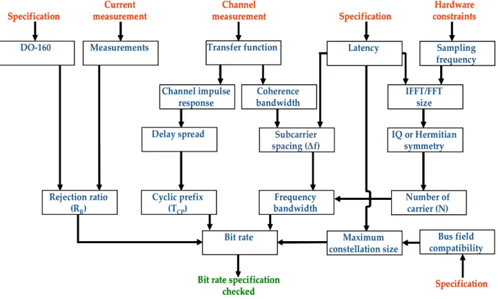
Fig. 2 summarizes the overall process of design. The purpose of this study is to quantify the parameters in order to calculate the bit rate which must complies with the different measurements, constraints and specifications:
- DO-160 gauge in paragraph II.A - Propagation channels in paragraph II.B - Aeronautic specifications in paragraph II.C - Hardware constraints in paragraph II.D - Fieldbus in paragraph II.E
Specification Number of carrier (N) Transfer function Hardware constraints Subcarrier spacing (Δf) Current measurement Specification Specification Channel measurement
Bit rate specification checked IFFT/FFT size Bus field compatibility Measurements DO-160 Rejection ratio (RR) Delay spread Cyclic prefix (TCP) Frequency bandwidth IQ or Hermitian symmetry Coherence bandwidth Latency
Bit rate Maximum
constellation size Channel impulse response Sampling frequency Specification Number of carrier (N) Transfer function Hardware constraints Subcarrier spacing (Δf) Current measurement Specification Specification Channel measurement
Bit rate specification checked IFFT/FFT size Bus field compatibility Measurements DO-160 Rejection ratio (RR) Delay spread Cyclic prefix (TCP) Frequency bandwidth IQ or Hermitian symmetry Coherence bandwidth Latency
Bit rate Maximum
constellation size Channel impulse
response
Sampling frequency
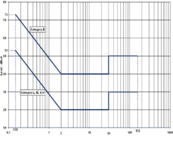
A. SNR definition and electromagnetic compatibility The DO-160 « Environmental Conditions and test Procedures for Airborne Equipment » describes several tests for aeronautical devices. It shows especially the conducted emissions tests, which are presented Fig. 3. This gauge can be interpreted from two different points of view. Firstly, it is possible to consider these levels as the maximal power that the PLC system can emit on the power network. However, this gauge is in common mode and the couplers transmit the data in differential mode. Therefore, a rejection factor between the common mode and the differential mode allows decreasing the disturbing differential mode noise on the modem, and increasing the transmit power. One can thus introduce a global rejection factor RR, taking these two
effects into account. Furthermore, the category (B or L, M and H) is not important since the ratio between the transmit power and the disturbing noise is independent of the DO-160 gauge. In addition, it is assumed that all the couplers are in the same category.
Figure 3. DO-160 gauge for conducted emissions B. Caracterization of the propagation channels
A study of the propagation channels has been done in [15] and allowed to define cyclic prefix duration and subcarrier spacing. The channel is composed of two couplers (inductive or capacitive), which are connected to one twisted pair of 32 meters length in accordance of the electrical wires length in the aircrafts. In this paper, three architectures are studied:
- The point-to-point architecture with capacitive couplers, Fig. 4,
- The point-to-point architecture with inductive couplers, Fig. 5,
- The point-to-multipoint architecture with inductive couplers, Fig. 6.
In the following, for the point-to-multipoint architecture, line 1 refers to the channel between coupler 1 and coupler 2 and line 2 refers to the channel between the coupler 1 and coupler 3.
Fig. 4 shows two capacitive couplers connected by one twisted pair. Capacitive couplers are plugged between the +270 V and the -270 V of the power network. They are composed of two capacitors and one high frequency transformer of 1:1 ratio for galvanic isolation. Communications are between V1 and V2 in differential mode and the harness is composed with one twisted pair.
Power Capacitive coupler 1 Capacitive Coupler 2 Twisted pair Load 1 +270 V -270 V V1 V2 32 m Power Capacitive coupler 1 Capacitive Coupler 2 Twisted pair Load 1 +270 V -270 V V1 V2 32 m
Figure 4. Point-to-point architecture with capacitive coupler Fig. 5 shows two inductive couplers connected by one twisted pair. Inductive couplers are plugged on one polarity (+270 V or -270 V) and are composed of one secondary coil, one magnetic torus and two primary coils. With this kind of coupler, it is necessary to divide one polarity in two wires. Thus, the harness is composed of one twisted pair for the +270 V and one other wire for the -270 V. However, transmissions are still in differential mode between V1 and V2. Inductive coupler 1 Inductive Coupler 2 V1 V2 Primary coil Twisted quadrifilar Secondary coil +270 V -270 V 32 m Load 1 Power Inductive coupler 1 Inductive Coupler 2 V1 V2 Primary coil Twisted quadrifilar Secondary coil +270 V -270 V 32 m Load 1 Power
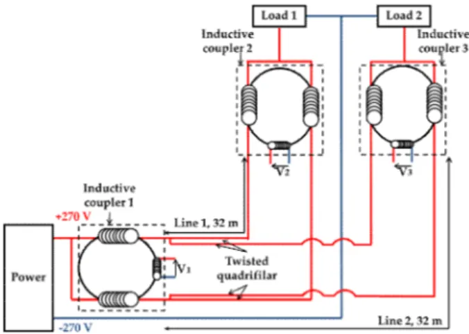
Figure 5. Point-to-point architecture with inductive coupler Fig. 6 represents the point-to-multipoint architecture with inductive couplers. In this architecture, three inductive couplers are plugged on the same polarity (+270 V or -270 V). The harness is therefore composed of one twisted quadrifilar for the +270 V and one wire for the -270 V. Like the other architectures, transmissions are between V1, V2 and V3 and in differential mode.
Two kinds of measurements are used to characterize the propagation channels:
- The transfer functions measurements - The RR measurements
The transfer function measurements have been performed with a network analyser on the [1;100] MHz bandwidth with a 5 kHz resolution. For each configuration, the transfer functions are measured between V1, V2 and V3. The insertion gains are presented in Fig. 7 for the different architectures. The insertion gains decrease linearly (in dB) with the frequency between 1 MHz and 40 MHz, and vary from -5 to -30 dB. Then, the insertion gains become relatively constant between 40 and 80 MHz and, after 80 MHz, decrease very rapidly.
0 2 4 6 8 10 x 107 -70 -60 -50 -40 -30 -20 -10 0 Frequency (Hz) In se r ti o n g a in ( d B )
point-to-point capacitive coupler point-to-point inductive coupler point-to-multipoint inductive coupler line 1 point-to-multipoint inductive coupler line 2
Figure 7. Insertion gain for all the architectures Taken into account these measurements and the previous work [15], it has been proposed a cyclic prefix duration of 500 ns and a subcarrier spacing of 70 kHz to adapt the OFDM parameters to the channel characterization, that are a delay spread of 100 ns and coherence bandwidth of 700 kHz. That represents a total OFDM symbol duration of 14.78 µs. The purpose of this previous work was to
define the OFDM symbol duration regarding the channel measurements to comply with real time constraints.
The measurements of common mode current and differential mode current show a RR value between 15 dB
and 25 dB.
C. Aeronautical Specifications
According to the aeronautic knowhow, FCS are controlled in speed and in position, with an operating frequency of 1000 Hz for the speed and 100 Hz for the position. However, speed control loop is a local control loop, and it will not use the HVDC network. Thus, only the position control loop can use PLC on the HVDC network. According to the common practice of the aeronautical field, command systems must work six times faster than the equipment that they command, which represents 600 Hz in our case. In addition, we must pay attention that there are several calculators in this position control loop, which require time processing. We consider that the PLC processing time must not exceed from 10 % to 20 % of the 1666 µs period (which correspond to 600 Hz). In our case, it represent from 167 µs to 334 µs.
Regarding the bit rate, the FCS is working with a bit rate of 1 Mbit/s. However, in order to foresee the future growth of avionic requirements, it is proposed a system providing a bit rate of 10 Mbit/s.
D. Hardware constraints
For the OFDM computation, a FFT algorithm is used. In this paper, the FFT processing time estimate is performed to check its compliance with real time constraints. In addition, FFT (or inverse fast Fourier transform (IFFT)) size is directly linked to the number of subcarriers of the OFDM symbol. Indeed, OFDM symbols in frequency domain are complex numbers that must be converted into real numbers in the time domain. To do that, there are two possibilities. The first one is the Hermitian symmetry, for which the FFT size is twice the number of subcarriers. The second one is IQ modulation, for which the FFT size is equal to the number of subcarriers. In order to decrease the processing time, the second technique is chosen. In the following, the FFT size is defined in accordance with the time constraints and the number of subcarriers is deducted.
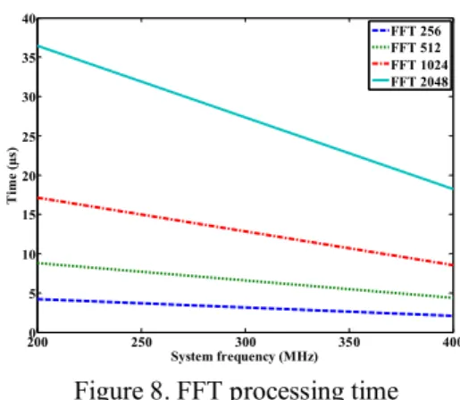
For the calculation of the FFT processing time, a simulation with Xilinx (core generator) software is done with a decimation algorithm of radix 4. In Fig. 8, the FFT processing time is presented regarding the sample frequency for different FFT sizes. The maximum sample frequency is chosen equal to 400 MHz conforming to the features of the aeronautic equipment. The results show that the FFT processing time is not problematic for the PLC system latency. In fact, a FFT size of 2048 samples at 200 MHz takes 37 µs, which is significantly below the real time constraint of 166 µs. This allows having enough latency margins for the design of the other blocks of the Figure 6. Point-to-multipoint architecture
transmission chain like the decoding, the synchronisation and the interleaver. In addition, since a 70 kHz of subcarrier spacing has been proposed, the best compromise is a FFT size of 512 or 1024, which represents a [1;37] MHz and [1;73] MHz bandwidth. Indeed, a 256 FFT size only allows to use a bandwidth of 19 MHz, while the [1;60] MHz bandwidth could be used as the transfer functions are low attenuated on this bandwidth. Furthermore, a 2048 FFT size requires a bandwidth of [1;149] MHz, which is too large compared to the measured frequency bandwidth.
2000 250 300 350 400 5 10 15 20 25 30 35 40 System frequency (MHz) T im e ( µ s) FFT 256 FFT 512 FFT 1024 FFT 2048
Figure 8. FFT processing time E. Fieldbus compatibility
To drive the actuators for FCS, three fieldbus are used today: ARINC 429 [16], MIL-STD-1553 [17] and ARINC 825 [18]. The size of the bus frame is 32 bits, 40 bits and 128 bits respectively. Considering the OFDM symbol duration of 14.28 µs without cyclic prefix [15], a bit rate of 10 Mbit/s requires 142 bits per OFDM symbols. If this bit rate constraint is checked, all of the fieldbus frames can be transmitted on one or two OFDM symbols, which implies duration of 28.56 µs for the ARINC 825 and 14.28 µs for the ARINC 429 and the MIL-STD-1553. It is far lower than the 166 µs constraint. Indeed, if the physical layer uses interleaving, all the data must be received and decoded before being transmitted to the actuator.
III. BIT RATE CALCULATION
With the transfer function measurements and DO-160 gauge, channel capacity can be computed on different frequency bands. The channel capacity is given by [19]:
) 1 ( log2 SNR B C (1)
where C is the channel capacity, B is the bandwidth, and SNR is the signal to noise ratio.
Since OFDM transmission is used, the bit rate is computed on each subcarrier and the bite rate over the total bandwidth is given by [20]:
N m m CP c SNR T f Bitrate 1 2 1 , log min 1 1 (2) R m mH
R
SNR
with
2where ∆f is the subcarrier spacing, TCP the cyclic prefix
duration, N the number of carrier, Hm the channel transfer
function on each sub carrier m, RR the common mode to
differential mode rejection ration, Γ the SNR margin and c the maximum constellation size.
IV. OPTIMIZATION OF OFDM PARAMETERS Table 1 summarizes the different possibilities of tested OFDM symbols.
Tableau 1. Summary of each configuration
Configurations Bandwidth (MHz) FFT size Maximum constellation size 1 [1;37] 512 BPSK 2 [1;37] 512 QPSK 3 [1;37] 512 16-QAM 4 [1;37] 512 64-QAM 5 [1;73] 1024 BPSK 6 [1;73] 1024 QPSK 7 [1;73] 1024 16-QAM 8 [1;73] 1024 64-QAM
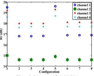
The purpose is to compare the impact of the frequency bandwidth and the maximum constellation size on the bit rate. The cyclic prefix duration is equal to 500 ns, which represents 18 samples on the [1;37] MHz bandwidth and 36 samples on the [1;73] MHz bandwidth. The SNR margin is equal to 4 and the number of subcarriers is equal to the FFT size. In the following, channel 1 refers to the point-to-point architecture with capacitive coupler, channel 2 refers to point-to-point architecture with inductive coupler, channel 3 refers to the point-to-multipoint architecture with inductive coupler line1 and channel 4 refers to the point-to-multipoint architecture with inductive coupler line 2. Fig. 9 represents the value of RR to reach 10 Mbit/s for each configuration.
Point-to-point architecture with inductive couplers offers the best results with a RR about 15 dB for all the configurations.
For the other architectures, the range of required RR is from
17 dB to 19.5 dB with the highest variations observed for the point-to-point architecture with capacitive coupler. For all the configurations, the required RR to reach 10 Mbit/s is
included in the range of the RR measured. In addition, the
configurations, which use BPSK modulation, offer the lowest performances (configurations 1 and 5). However, for the configurations 2, 3, 4, 6, 7 and 8 the same RR is required
for each architecture.
The conclusions are that 16-QAM and 64-QAM modulations are useless in all the architectures and configurations since the bit rate gain is negligible. Similarly, the [1;73] MHz bandwidth is not interesting because it does not increase the bite rate but increases the processing time due to the rise of the FFT size. Thus, in order to have a bit rate equal to 10 Mbit/s, the best compromise is to use a maximum constellation size of QPSK on the [1;37] MHz bandwidth.
1 2 3 4 5 6 7 8 14 15 16 17 18 19 20 Configuration R r (d B ) channel 1 channel 2 channel 3 channel 4 Figure 9. RR required for 10 Mbit/s
We now evaluate the bit rate in the case of the most favourable condition, with RR=25 dB, which represents the
highest measured value. The bit rate is calculated for each configuration and is presented in Fig. 10. The point-to-point architecture with inductive couplers offers the best performances with a bit rate value between 30 Mbit/s and 72 Mbit/s. The two other topologies provide a lower bit rate value (between 20 Mbit/s and 45 Mbit/s). As in the previous simulations, the [1;73] MHz bandwidth is useless because configurations 5, 6, 7 and 8 offer bit rates equal to those of configurations 1, 2, 3 and 4, respectively. Regarding the maximum constellation size, 16-QAM modulation allows an important bit rate gain compared to BPSK and QPSK modulation. However, the bit rates are similar between 16-QAM and 64-16-QAM modulation. Then, 64-16-QAM is not used to simplify the transmission system.
1 2 3 4 5 6 7 8 10 20 30 40 50 60 70 80 Configuration B it ra te (M b it /s ) channel 1 channel 2 channel 3 channel 4
Figure 10. Bit rate calculation for a RR of 25 dB
V. CONCLUSION
In this paper, a parametric study is presented in order to define OFDM parameters (the frequency bandwidth, the FFT size, the number of subcarriers and the maximum constellation size) for a PLC OFDM transmission in aircraft environment, in accordance with bit rate and real time
constraints. This parametric study takes into account the analysis of the propagation channel, the DO-160 gauge for conducted emissions with a SNR chosen in the worst case and hardware constraints.
ACKNOWLEDGMENT
This study is funded by Sagem and the harness was provided by Safran Engineering Services.
REFERENCES
[1] HomePlug Av specification, Version 1.1, May 21, 2007
[2] J. Granado, A. Torralba and J. Chavez, “Using broadband power line communications in non-conventional applications”, IEEE Transactions on consumer electronics, Vol. 57, Np. 3, pp. 1092-1098, August 2011
[3] P. Tanguy and F. Nouvel, “In-Vehicle PLC Simulator Based on Channel Measurements”, International conference on intelligent transport system telecommunication (ITST), pp. 1-5, 2010.
[4] G. Sung, C. Huang and C Wang, “A PLC transceiver design of in-vehicul power line in flexray-based automotive communication systems”, IEEE International conference on consumer electronics, pp. 309-310, 2012.
[5] M. Mohammadi et al., “Measurement study and transmsission for in-vehicule power line communication”, pp. 73-78, 2009.
[6] S. Barmada, L. Bellanti, M. Raugi, and M. Tucci, “Analysis of Power-Line Communication”, Channels in Ships, IEEE Trans. on Vehicular Technology, vol. 59, no. 7, pp. 3161-3170, September. 2010.
[7] M. Antoniali et al., “Measurements and analysis of PLC channels in a cruise ship”, ISPLC, pp. 102-107, 2011.
[8] A. Akinnikawe and K. Butler-Purry, “Investigation of broadband over power line channel capacity of shipboard power system cables fo ship communication networks”, IEEE, pp. 1-9, 2009.
[9] S. Barmanda et al., and M. Tucci1, “Design of a PLC system onboard trains: selection and analysis of the PLC channel”, ISPLC, pp. 13-17, 2008.
[10] K. Ming Liu and Daming Jiang, “PLC used in the train control simulation system”, IEEE, pp. 1-4, 2012.
[11] S. Bertuol et al., “Numerical Assessment of Propagation Channel Characteristics for Future Application of Power Line Communication in Aircraft”, 10th Int. Symp. on EMC, pp. 506-511, September. 2011. [12] V. Dégardin et al., “Theoretical approach to the feasibility of power-line communication in aircrafts”, IEEE Trans. VT, vol. 62, no. 3, pp. 1362-1366, March. 2013.
[13] K. Kilani et al., “Impulsive noise generated by a pulse width modulation inverter : modeling and impact on powerline communication”, ISPLC, pp. 75-79, March. 2013.
[14] DO-160,Environmental conditions and test procedures for airborne equipment, Standard, 2007.
[15] T. Larhzaoui et al. , “Analysis of PLC Channels in Aircraft Environment and Optimization of some OFDM Parameters”, ICSNC, pp.1-5, October. 2013.
[16] Arinc 429, “Specification Tutorial”, November. 2011. [17] An Interpretation of MIL-STD-1553B, SBS Technologies, Inc.
[18] R. Kmeppel, “Standardisation of CAN network for airborne use through ARINC 825”,iCC, pp.1-8, 2012.
[19] C.. Shannon, “A Mathematical Theory of Communication, Bell System Technical Journal”, vol. 27, pp. 379-423 and 623-656, July and October, 1948
[20] J.M. Cioffi, “A multicarrier primer”, technical report, ANSI. 4/91-157 Commettee contribution, November. 1991.