Page 1 of 10 IAC-12, C2.6.6,x13735
RADIATION SHIELDING OF COMPOSITE SPACE ENCLOSURES G. Atxaga1
TECNALIA, Spain, [email protected] J. Marcos2, M. Jurado3, A. Carapelle4, R. Orava5
Space electronic systems employ enclosures to shield sensitive components from space radiation. The purpose of shielding is to attenuate the energy and the flux of ionizing radiation as they pass through the shield material, such that the energy per unit mass (or dose) absorbed in silicon is sufficiently below the maximum dose ratings of electronic components.
The received radiation amount varies significantly depending on several variables that include mission parameters (orbit, altitude, inclination and duration), spacecraft design (spacecraft wall thickness and panel-enclosure location). To achieve the optimum shielding with the minimum weight, all these variables have to be considered in the design. Energetic particles, mainly electrons and protons, can destroy or cause malfunctions in spacecraft electronics. The standard practice in space hardware is the use of aluminium as both a radiation shield and structural enclosure. Composite structures show potential for significant mass savings. However, conventional graphite epoxy composites are not as efficient shielding materials as aluminium because of their lower density, that is, for the same mass, composites provide 30 to 40% less radiation attenuation than aluminium.
A solution is to embed high density (atomic weight) material into the laminate. This material, typically metallic material, can be dispersed in the composite or used as layers in the laminate (foils).
The main objective of the “Radiation Shielding of Composite Space Enclosures” (SIDER) project is the development of the technologies and tools required to obtain lightweight, safe, robust and reliable composite structures. Two different strategies are being analysed as alternatives for radiation shielding: and he incorporation of a high density material foil.
This paper will present and analyse the radiation shielding obtained by the incorporation of nanomaterials in composite structures.
1 TECNALIA. Transport Unit, Spain, [email protected] 2
TECNALIA. Transport Unit, Spain, [email protected] 3 TECNALIA. Transport Unit, Spain, [email protected] 4 CSL, Belgium, [email protected]
5
Page 2 of 10 I. INTRODUCTION
The space radiation environment is a complex and varying phenomenon that depends of many factors including orbit, time of year and solar activity. Solar flares can dramatically alter the radiation exposure of a satellite with no more than a few hours’ notice. A proper understanding of the mission requirements and the likely effects of radiation on satellite components help ensure maximum operational reliability.
Energetic particles, mainly electrons and protons, can destroy or cause malfunctions in spacecraft electronics. Therefore adequate protection for the electronics has to be provided by the electronics housing together with local shields.
Given the current trend toward Commercial Off-The-Shelf (COTS) components, the orbital lifetime of space systems is substantially reduced since these components are not designed for high radiation tolerance. Therefore, systems with COTS electronics require enclosures whose mass is determined by substantial shielding requirements, rather than structural requirements. Thus, significant weight penalties can result when shielding space systems that use COTS electronics and operate in high radiation environments.
To reduce the structural weight, satellite designers use composite materials which have higher strength to weight ratios than aluminium. Composite materials are central in aerospace applications due to the weight savings that could result from using low density polymer matrix composites made from high modulus, high strength fibres. The attributes of composites include high specific strength (strength per unit weight) and stiffness, corrosion and fatigue resistance, tailorable conductivities, controlled thermal expansion and the ability to be processed into complex shapes. They are lightweight, which is critical for any aerospace platform and the physical, mechanical, electrical and thermal properties of composites are highly tailorable, which can also afford them multifunctionality. In Figure 1, the prototype developed in the frame of the MULFUN project (coordinated by TECNALIA) is presented. Around 60 % of mass saving was obtained [1]. However, conventional graphite epoxy composites are not as efficient radiation shielding materials as aluminium (composites provide 30 to 40 % less radiation attenuation, which is considered primary design driver). Therefore, additional shielding is required [2].
Figure 1: Composite electronic box (MULFUN project).
From the classical theory of Bethe it can be shown that to minimize mass of the shield, low atomic number (low Z) elements are most effective on per unit mass basis. If it is necessary to reduce the thickness of the shield, then high atomic number (high Z) elements are most effective on per unit thickness basis. A “heavy” material (high Z i.e. high atomic number) is better absorber of electrons and bremsstrahlung than a low Z material even if the production of bremsstrahlung is higher in materials of high atomic number. However, a high Z material is less effective in stopping protons. Therefore structures where low Z and high Z layers are combined to get effective radiation shielding are in interest [2].
Preliminary transport computations showed that shielding designs utilizing this concept can provide weight savings in the excess of 25 % over aluminium in electron dominated environments such as GPS and Geosynchronous orbits. A multilayered shield of 1,016 mm composite / 0,127 mm tantalum / 1,016 mm composite with a combined areal weight of 0,61 g/cm2 has the same shielding effectiveness of 0,8 g/cm2 aluminium, resulting in about a 25 % weight saving. Similar results were achieved when tungsten was used as the high Z material. This is significant because tungsten has almost three times the thermal conductivity of tantalum [3].
In SIDER, composite materials will be developed and modelling and test for space equipment demonstrators will be performed. Countermeasures as tungsten layers and nano-conductive materials will be evaluated at simple samples to assess its shielding capabilities for composites boxes. The activity will also adapt / enhance analytical tools and the capabilities, procedures and quality for the radiation facilities directed to composite testing.
SIDER project aims to:
• improve and apply novel technologies for the improvement of the radiation shielding of composite materials.
Page 3 of 10
• develop analytical tools for radiation design of composite structures.
• develop testing technologies for investigation of radiation shielding properties of the composite structures.
This paper presents the results obtained in the first phase of the project. It is focused in the radiation shielding obtained by the incorporation of nanomaterials in composite structures.
II. MAIN REQUIREMENTS AND SPECIFICATIONS
The energy spectra of ionizing radiation of the following two orbits have been considered in the study:
- GSO,
- low orbit of 1600km altitude.
The selected typical orbits and their maximum values of integral density of particles fluences considered are presented in Table 1.
Altitud e, [km] Integral density of TRB protons fluence, [cm-2s-1] SCR protons fluence, [cm-2/year]1 Integral density of TRB electrons fluence, [cm-2s-1] 1600 105 (Е=0.1-400MeV) 4·1010 9·105 35794 9·105 (Е=0.1-3 MeV) 4·1011 4·105
Table 1: Selected orbits.
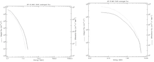
Figure 2 and Figure 3 present the averaged trapped protons and electrons of each of the orbits:
Figure 2: GSO Orbit Spectra. Left) Averaged trapped proton. Right) Averaged trapped electron.
Figure 3: LEO Orbit Spectra. Left) Averaged trapped proton. Right) Averaged trapped electron
III. NANOTECHNOLOGIES STATE OF THE ART
CNTs have many properties that make them perfect candidates as the basic building block for multifunctional materials. Their high strength, toughness, low weight, their low molecular weight and ability to form lightweight composites, make them ideal for use as radiation shields.
Several issues have to be solved to transfer the potential properties of the nanofillers to the polymer composite. Adding small amounts of nanoreinforcements will significantly increase the viscosity of polymer resins, which makes the dispersion and resin flow extremely difficult. Thus, when employing traditional manufacturing processes such as RTM/infusion or autoclave using particle filled resins, two main problems arise, the increased viscosity of the resin and the filtration of nanoparticles effect that are retained by the fibre preform, leading to defective laminates. These drawbacks are even higher for aerospace composites due to the complexity of the typically used monocomponent epoxy systems and the high carbon fibre volume contents required. The target of the project in this case has been established on how to overcome the still pending technical challenges: optimal and stable dispersion of nanofillers into the resin so that the mixture can be stable across time without any re-agglomeration effect, suitable nanofiller/resin interfacial bonding and preserving integrity of nanoreinforcements during dispersion process.
A non-uniform dispersion of CNTs in the polymer matrix is considered as the most significant factor affecting the overall properties. The large contact area of CNT and the relatively strong inter-tube attraction via van der Waals forces make the CNT spontaneously form agglomerates, thus making their dispersion in polymeric matrices more difficult; even re-agglomeration effects during polymer curing process haven been reported. Significant research
Page 4 of 10 efforts have been devoted to solve this issue by either
mechanical dispersion methods or surface modification of CNTs through chemical and physical methods.
One interesting alternative to the integration of nanoreinforcements directly into the resin is the preforming of nanoreinforcements into thin mats with well-controlled dispersion and porous structure, so called in the literature “buckypaper”. In a later step the preform can be infiltrated with polymers following traditional methods such as infusion, autoclave, etc. This type of nanostructured performs are manufactured by filtration of stable nanotube suspensions with surfactants or binders so that to produce thin mats. Due to nanotube distribution, high aspect ratios and strong inter-tube Van der Waals attractions, they have enough resistance for its handling, This way, CNTs remain well dispersed within the final composite structure and viscosity associated problems above mentioned are mitigated, while allowing achieving high CNTs loadings in composite structures. Besides, CNTs can be aligned during filtration by the use of electromagnetic fields, which is relevant for electrical conductivity issues as well as sensing and actuating capabilities. This technology will indeed enable an easier integration of CNTs into selective areas of the composite; which is not possible by the use of doped bulk polymers with CNTs. In Figure 4, CNT buckypaper developed in TECNALIA is presented.
Figure 4: Buckypaper manufactured in TECNALIA.
Some contribution in the field of CNT buckypaper based composites in recent years has been made by different groups. All of them reported on projects on buckypaper based composites, aimed at improved fire resistance [4], thermal resistance [5], electrical conductivity (EMI shielding and lightning strike protection) [6], [7], [8] impact resistance and overall mechanical properties [9], though much of the work is still in progress.
Although large-scale production of CNT buckypaper based composites is, for various reasons, yet not feasible, the interest in the process is apparent from recent investment in the technology. Research to develop technologies to produce CNT buckypapers
and their composites with potential use in aerospace structures are under way, and further developments of this technology are expected along the project.
IV. MATERIAL SELECTION
This paper is focused in the use of nanotechnologies as radiation attenuators.
Composite materials are central in space applications due to the weight savings that could result from using low density polymer matrix composites made from high modulus and high strength fibres. The main advantages of composites include high specific strength (strength per unit weight) and stiffness, corrosion and fatigue resistance, tailorable thermal conductivities, controlled thermal expansion and the ability to be processed into complex shapes. Advantage and challenge at the same time is the possibility to design all the thermo-mechanical properties as orthotropic ones.
The MTM57 – M40J prepreg from Advanced Composite Group (areal weight 300g/m2 carbon fibre) was purchased.
The resin selected to carry the nanotechnology development activities is an epoxy resin, a tricomponent formed by ARALDITE LY 1556 (A compound); DYHARD D50EP (B compound); DYHARD UR500 (C compound). The main driver for its selection was its compatibility with the resin used in the prepreg material selected as basis in SIDER project.
Two types of nanofillers with commercial availability have been considered: carbon nanotubes CNTs and tungsten nanoparticles.
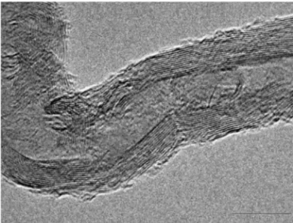
One approach for strengthening the durability against radiation is the addition of fillers to the matrix materials. Carbon nanotubes (CNT, Low Z material) have inspired scientists and engineers to examine a wide range of potential applications as exotic filler materials, since the discovery of their extraordinary mechanical, electrical, magnetic and thermal properties. The carbon nanotubes selected for this study were commercial multi-walled carbon nanotubes (MWCNT), supplied by Arkema with a purity of > 90 % (ref. Graphistrength C100, Figure 5).
Page 5 of 10 Figure 5: TEM photographs of the Graphistrength
C100 multi-walled carbon nanotubes.
Because, their specials properties as high density (19,25g/mL), low reactivity and toxicity, and the possibility of blending into plastic for extrusion or moulding and long-term storage possibilities, tungsten could be used for shielding applications at nuclear facilities instead of other materials such as lead and steel. Tungsten nanoparticles with reference 9820XH were supplied by SkySpring nanomaterials, Inc.
V. EXPERIMENTAL TECHNIQUE
The work has focused on the preparation, dispersion, adhesion and orientation of nanofillers into composite laminate for obtaining the required functionality. The target has been to optimize the two technologies proposed for this integration (direct resin bulk doping and buckypaper manufacturing for later resin infiltration) in order to obtain:
• An optimal and stable dispersion of nanofillers into the final laminate
• A suitable nanofiller/resin interfacial bonding
• Preservation of the integrity of nanoreinforcements during integration process. As aforementioned, two approaches to integrate the nanomaterials in the composite structure have been followed:
• Bulk doping strategy: Dispersion techniques such
as three roll mill, high shear mechanical stirring, etc. have been studied in order to obtain the best dispersion of nanofillers into the resin and good interfacial bonding. Once the resin is doped, laminates have been manufactured by hand lay-up and autoclave curing. With this approach the
maximum nanofiller loading level is determined mainly by the initial viscosity of the resin.
Figure 6: Doped resine:30% tungsten and 0,5%CNT.
From the studies performed, it can be observed that the epoxy resin can be doped with high percentage of W particles keeping manufacturability parameters (viscosity around 4000-5000cp). A maximum content of 0,5% CNT and 30% W can be achieved when combining both fillers to dope the epoxy resin.
• Buckypaper (BP) strategy: The method for
production of buckypapers has been based on a multiple-step process that includes dispersion of CNTs/tugsten nanofillers in a solvent and filtration processes; ultrasonication, mechanical stirring and the use of surfactants to obtain a stable nanofiller suspension before filtering. The manufactured buckypaper have been integrated into prepreg lay-up for later curing in autoclave. Comparing with bulk doping approach, localized higher nanofiller content can be obtained with buckypaper.
Figure 7: Buckypaper: 6 % MWNT - 94% of W particles.
A high CNT loading can be obtained with BP. These are porous materials; therefore, a good
Page 6 of 10 impregnation with epoxy resin is assured. On the
other hand, high contents of CNT in combination of W nanoparticles can be obtained (50 % CNT+50 % W). Thanks to the CNT network W nanoparticles decantation is not produced
In both approaches, doped laminate coupons with different percentage of nanofillers have been manufactured with the following stacking sequence [0, +45, 90, -45,Central layer (doped resin or BP),-45, 90, 45, 0] to be used in subsequent testing activities. In Figure 8 and in Figure 9, a detail of the manufactured laminates is presented. Reference coupons without any nanofiller inclusions have also been fabricated for reference purposes.
Figure 8: Doped resin. TEC 2: 88%W.
Figure 9: Buckypaper 6%CNT/94%W.
In Table 2 the samples manufactured are detailed:
Table 2: Manufactured samples.
VI. SIMULATIONS
VI.I Simulation environment
The simulations were performed using Geant4 version 9.5. The simulation reference was default Geant4 aluminium. Material definitions included correction factors, derived from the first measurement campaign, to estimate impurities on the layers.
The layer thicknesses that were studied are the following:
• Aluminium with thickness of 1 and 2 mm
• Tungsten of 50 and 100 µm
• Stainless Steel of 50 µ m
• Prepreg of 215 µm
The thicknesses and compositions of the prepreg and steel layers were optimized to the results of the first test campaign measurements with 20 MeV protons.
The incoming particles and energy regions that were studied are:
• Protons of 1-100 MeV
• Electrons of 1-20 MeV
• Gamma of 1-20 MeV
The effect of the materials in terms of absorbed energy and dose was estimated by using a scoring layer of silicon with thickness of 300 µ m. This was placed right after the samples in the simulation models.
VI.II Simulations
Secondary radiation produced with the spacecraft material by trapped protons and interactions with cosmic rays provide an important, and at times, dominant radiation environment for the instruments. Energy loss measurements will not provide information about the type of radiation that the components will experience behind the shielding layers. Therefore, in the simulations, in addition to
Ref-TEC Central Layer
TEC1 Doped resin with 2,21%CNT TEC2 Doped resin with 88%W TEC3 Doped resin with 63%W TEC4 Doped resin with 30%W/0,5%CNT TEC5 Buckypaper 6%CNT/94%W TEC6 Buckypaper 24%CNT/76%W TEC7 Buckypaper 50%CNT/50%W TEC8 Buckypaper 76,60%CNT/23,4%W TEC9 Buckypaper 100%CNT
TEC11 0,Buckypaper 76,60%CNT/23,4%W,90,Buckypaper 76,60%CNT/23,4%W,0
TEC 13
0,doped resin 2,21%CNT,90,doped resin 30%W/0,5%CNT,0,doped resin 88%W,90, doped resin 88%W,0, doped resin 88%W,90, doped resin 30%W/0,5%CNT,0, doped resin 2,21%CNT
Protons
Page 7 of 10 studying the energy loss of the particles, overall
radiation dose is measured in a layer behind the sample under studies. This is done in scoring layer of Silicon with thickness of 300 µ m. The material and the thickness were selected to represent the standard electronics components inside a spacecraft.
The number of incoming particles was set to 10.000 to reduce the required CPU time for the calculations.
VI.II.I Protons
Simulations of interactions of protons were made in the energy region of 1-100 MeV. Most of the effect the thin shielding materials have to the incoming radiation will occur in the lower end of the selected energy region. Therefore particle energies higher than 100 MeV were not included in the simulation models. Though particles with higher energies contribute to Single Event Upsets (SEU), their effect to overall dose experienced by the components is very small due to the small number of these types of particles.
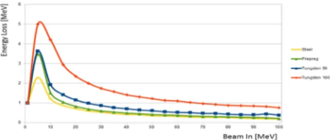
Figure 10 shows simulated energy loss of protons traversing layers of different materials. As expected, the high Z material, Tungsten, has the highest effect on the kinetic energy of the incoming protons. At lower energies, layers made from Prepreg have equal effect on the particle energies as 50 µm of Tungsten. Overall, the effect of a Prepreg layer is better or equal as 50 µm layer of Steel.
Figure 10: Energy loss of protons traversing through sample layers. Tungsten 50 and 100 describe the thickness of the layers in microns.
When the dose of the incoming radiation is compared, it can be seen in Figure 11, that since the 100 µm layer of Tungsten has the highest effect on proton energy, it also suffers from highest dose coming from secondary particles. However, this is only visible on lower energies since at higher energies the rate of secondary particles is less affected by the properties of a thin layer. This is due to the drop in probability of interactions.
Figure 11: Dose in Silicon scoring layer after the samples from proton beams
VI.II.II Electrons
Though most of the incoming electrons have kinetic energy in the region of 1-7 MeV, the studies were expanded up to 20 MeV. This was done to study the effects of secondary particles that are produced in the proton interactions.
From Figure 12 it can be seen that only the layers with high Z materials have effect on incoming electron energy. The improvement between the two Tungsten samples can be seen to be directly proportional to the material thickness.
Figure 12: Energy loss of the electrons traversing the sample materials.
Figure 13 shows the measured dose on the scoring layer after the samples.
Figure 13: Dose on the scoring layer from electron beams of various energies.
VI.II.III Gamma-radiation
Main source of the gamma-radiation that has an effect to the spacecraft devices is coming from the interactions of the charged particles with the
Page 8 of 10 spacecraft materials. Therefore a separated study was
made to map the possible effects of this type of radiation. It was seen that the effect of the secondary gamma-rays is minimal in comparison to the other sources of radiation. Figures 14 and 15 show the energy loss of incoming gamma-rays, and the measured dose on the scoring layer, respectively.
Figure 14: Energy loss of gamma-rays traversing the sample materials.
Figure 15: Measured dose on the scoring layer from gamma-rays traversing through the sample materials.
VI.II.IV Dependence on the angle of incidence Effects of the angular variations of the incoming radiation were also studied. Since the materials are homogeneous, the expectation would be that the increased angle would increase the energy loss felt by the incoming particles since they have increased distance to interact with the matter. Simultaneously this should increase the dose measured with the scoring layer, since the number of secondary particles should also increase. By using nanoparticles, the angular variation will have larger effects than with uniform bulk materials.
Figures 16, 17 and 18 show the effects of varying the angle of incoming radiation from 0 to 45 degrees.
Figure 16: Energy loss of protons traversing through 50 µm of Tungsten (left) and measured dose on scoring layer (right). The energy loss is in MeV and the dose in µGy.
Figure 17: Energy loss of protons traversing through 50 µm of Steel (left) and measured dose on scoring layer (right). The energy loss is in MeV and the dose in µGy
Figure 18: Energy loss of protons traversing through Prepreg layer (left) and measured dose on scoring layer (right). The energy loss is in MeV and the dose in µGy.
VI.III Optimization
From the simulations it can be seen that the properties of a Prepreg layer correspond to the properties of a 50 µ m Steel layer. Therefore, when optimizing the multi-layered structures, these two material layers can be considered equal in terms of shielding performance.
Since the goal is to produce samples that are lighter than Aluminium in weight, and have similar or better shielding properties against incoming radiation, there are only few combinations that can be built from the available materials. To produce composition that has at least as good shielding properties than 1 mm of Aluminium, and by taking account the simulation results, there are two possibilities to construct the samples. When using the best material, 100 µm of Tungsten, there is space only for two layers of Prepreg in order to keep the overall density and thickness smaller than with aluminium.
Page 9 of 10 VII. TEST CAMPAIGN
Proton Irradiation: Samples have been submitted
to 20 MeV protons beam under vacuum. The energy of the protons after the samples has been measured. Figure 19 illustrates the measurement principle:
Incoming mono energetic proton beam of 20 MeV
Energy In te n si ty 2 0 M eV Shielding sample outgoing proton beam of x MeV (no more monoenergetic)
D et ec to r Energy In te n si ty X M eV
Figure 19: Proton measurement principle
For Gamma Irradiation a 60Co of 1.17 µCi source has been used with a 3 inches diameter NaI.Tl scintillator detector (Ortec Model 905.4).
For Electron Irradiation a medical electron accelerator was used to irradiate samples with 6 MeV electrons beam. The “electron mode” was used, removing the target. The electron beam has a maximum energy of 6 MeV. The intensity of the beam was fixed and the irradiation time was fixed to obtain a dose of 6 cGy (eq. water) under 13 mm of water. The irradiation field was 30 x 30 mm
Results obtained in the test campaign are depicted in Figure 20, Figure 21 and Table 3.
Figure 20 represents the efficiency obtained in each sample, meaning the improvement obtained comparing the areal density of the material under study versus the aluminium one for the same level of shielding (AALTO 22 corresponds to the aluminium reference and AALTO17 to the composite one).
Figure 20: Proton irradiation test results.
As it can be observed, at 20 MeV a higher decrease in the protons energy is obtained in the samples that incorporate nanotechnologies.
Figure 21 shows the results obtained in the Gamma Irradiation tests. The gamma peak at 1.33 MeV the composite sample is a more efficient shielding than Al. However, it is less efficient for the 1.17 MeV peak.
Figure 21: Gamma irradiation test results.
Table 3 presents the results obtained in the Electron Irradiation tests. The studied composite material is not more efficient than aluminium. New combinations will be tested in the next phases of the project.
No shield Al 2mm shield TEC13_1 shield
Calculated dose
Radfet 1 (cGy) 78.92 18.34 78.13
Calculated dose
Radfet 2 (cGy) 80.52 23.92 82.91
Table 3: Electron irradiation test results.
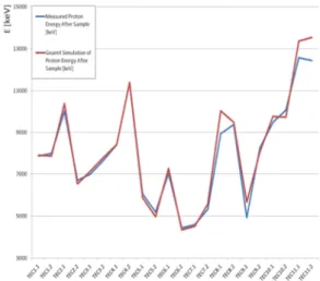
VIII.CORRELATION BETWEEN SIMULATION AND EXPERIMENTS
Simulation model follows closely with test results (protons – 20MeV) obtained in the test campaign (Figure 22).
20 MeV protons is not totally representative of the energies that could be observed, but the model will improve with higher energies.
Simulation models can predict composite behaviour. However, just considering proton beam does not give complete picture. Shower induced at
0 0,5 1 1,5 2 2mm Al TEC13.1
% absorbed in shield at 1.17MeV/aerial density % absorbed in shield at 1.33MeV/aerial density
Page 10 of 10 each boundary is full of charged and neutral particles.
Therefore, it is necessary consider all interactions the system to advance the science
Figure 22: Correlation between results obtained in simulations and in the test campaign.
IX. CONCLUSIONS
The use of nanotechnologies has been considered to improve the radiation shielding behaviour of composite materials.
Manufacturing approaches to incorporate the nanofillers into the laminates have been developed. Different strategies have been followed: doping of the resin and buckypapers.
Process parameters have been optimized and samples with different percentages of nanofillers have been manufactured.
Simultations and tests at sample level have been carried out.
A correlation of the results obtained indicates simulation models can predict composite behavior. Secondaries influence will be considered in further steps of the study.
Promising results have been obtained with the nanomaterials in the Proton Irradiation test (20 MeV). However, the strategy to shield against electrons will have to be further studied in the next steps of the project.
Results presented in the current paper correspond to the first stage of SIDER project. In further steps, simulations in the whole energy spectra and a Second Test campaign will be carried out in order to select the most promising material.
X. REFERENCES
1 “Multifunctional Structures” MULFUN, FP6. Project data package.
2 “The development of lightweight radiation shielding composite for electronic enclosures.”A. Abusafieh, G. Trembly, G. Krumweide, J. Marks, S. Roske. 44th International SAMPE Symposium. 3 “The development of lightweight radiation
shielding composite for electronic enclosures.”A. Abusafieh, G. Trembly, G. Krumweide, J. Marks, S. Roske. 44th International SAMPE Symposium.
4 “Influence of carbon nanotube reinforcement on the processing and the mechanical behaviour of carbon fiber/epoxy composites”, A. Godara, L. Mezzo, F. Luizi, A. Warrier, S.V. Lomov, A.W. van Vuure, L. Gorbatikh, P. Moldenaers, I. Verpoest, Carbon, Volume 47, Issue 12, October 2009.
5 “Fire retardancy of clay/carbon nanofiber hybrid sheet in fiber reinforced polymer composites”, Z Zhao, J Gou, S bietto, C Ibeh, D Hui, Composites Science and Technology 69 (2009). 6 “Thermal and electrical properties of carbon
nanotube reinforced cyanate ester polymer”, V Calard, A Vavouliotis, S Forerro, L Pambaguian, Viennano 09 Conference, March 18-20, 2009, Vienna, Austria.
7 “Carbon nanofiber paper for lightning strike protection of composite materials”, Composites: Part B J Gou, Y Tang, F Liang, Z Zhao, D Firsich, J Fielding, (2009).
8 “Electromagnetic interference shielding properties of carbon nanotube buckypaper composites”, JG Park, J Louis, Q Cheng, J Bao,J Smithyman, R Liang, B Wang, C Zhang, JS Brooks, L Kramer, P Fanchasis and D Dorough, Nanotechnology 20 (2009).
9 “Experimental design and optimization of dispersion process for single-walled carbon nanotube bucky paper”, J.H. Gou, Z. Liang, B. Wang, International Journal of Nanoscience, 2004, 3.
XI. ACKNOWLEDGEMENT
The research leading to these results has received funding from the European Community’s Seventh Framework Programme (FP7/2007-2013) under Grant Agreement nº 262746 (SIDER project).