(1.1)
SENSITIVITY ANALYSIS WITH UNSTRUCTURED FREE MESH GENERATORS
IN 2-D AND 3-D SHAPE OPTIMIZATION.
P. Duysinx, W.H. Zhang, C. Fleury.Aerospace Laboratory, LTAS, University of Liège B-4000 LIEGE, BELGIUM.
ABSTRACT.
Shape optimization has to consider new progress in mesh generators to take full benefits from the use of free unstructured meshes in realistic industrial optimization. The main difficulty relies in the mesh flow determination during sensitivity analysis. The authors present their experience in applying smoothing techniques to transmit boundary perturbations to the inner mesh. It is explained how smoothing can be used to evaluate velocity fields in a simple and inexpensive way while guarantying reliability, efficiency and precision. A wide range of smoothing procedures are compared and confronted with other velocity field approaches to investigate their advantages and drawback. Finally, applications of smoothing procedures in the commercial optimization package OPTI-SAMCEF are described.
1. INTRODUCTION.
As a result of prolific research efforts, structural shape optimization has reached sufficient maturity to handle real-life problems in industrial environment. Now, it is stated as a mathematical programming
j i
problem in terms of an objective function f(z), design restrictions c (z) and design variables z .
Due to the function evaluation cost, this non-explicit and nonlinear optimization problem is replaced by a sequence of conservative convex approximated explicit sub-problems which are generally solved by mathematical programming algorithms. These first order approximations require first to perform an accurate efficient and reliable sensitivity analysis to get the necessary gradient information. In shape optimization software, great care is devoted to sensitivity analysis since it requires the major part of computational effort. As reported by Braibant , integrating new free mesh generators and computer aided design facilities3 into a modern and powerful shape optimization tool is a problem which is not completely solved. First shape optimization tools used only regular F.E. meshes generated by a transfinite technique. In this case,1-2 sensitivity analysis is performed in an easy and natural way by using the intrinsic surface coordinates of transfinite mesh for grid deformation. Even though this natural method proved to be reliable and robust in many problems, it revealed several limitations such as severe mesh distortions for large geometry variations
(2.1)
(2.2)
(2.3)
(2.4) and somewhat tedious and inflexible when applied to complicated shapes. Since few years, the emergence of new reliable and efficient free meshers is very attractive, but their application is much more complicated for sensitivity analysis. Unlike transfinite mesh, one cannot trust in free mesh generator for grid perturbation. Mesh topology has to be frozen and a repositioning criterion has to be used to determine mesh flows relative to boundary changes. Since the end of 80's, several research works5-6-7-8 proposed to link mesh flows to physical laws. The velocity field is determined based on the mechanical behavior of the structure (In Ref.5 fictitious loads are used whereas prescribed displacements are preferred in the last ones). Recently, local approaches have also appeared; they consist in relocating only the outer layer of F.E. while interior nodes remain unchanged. Ref.9 has compared this method transfinite approach. In the present research, the authors focussed on applying Laplacian smoothing techniques to the velocity field problem with unstructured meshes. This method can either be related to the physical approach as a solution to the Poisson's equation or be regarded as a geometric approach to the mesh flow problem. The efficiency and reliability of these inexpensive methods were successfully tested and then integrated in the commercial F.E. and optimization package OPTI-SAMCEF .4
2. DISCRETE SEMI-ANALYTICAL APPROACH IN SENSITIVITY ANALYSIS WITH UNSTRUCTURED FREE MESHES.
As the F.E. analysis is used, the semi-analytical method is applied to the discrete model. The F.E. discretization of the equilibrium equation of the structure is written in terms of the generalized stiffness matrix K, displacements q and forces g :
i Differentiating equation (2.1) gives the displacements sensitivity with respect to design variable z :
The semi-analytical approximation consists in evaluating the derivatives of the stiffness matrix and generalized forces by finite difference:
i i i i
In order to generate the stiffness matrix K(z +äz ) and load vectors g(z +äz ), the new position of any nodal i
point P after perturbation of variable z is first required:
i
(2.5) i
first derivative of the position of any point P(x) with respect to a change of design variable z . One can also
i i
interpret the velocity field V as the law giving first order perturbations äx of nodal position after a small i
variation of boundaries associated to a change of design variable z .
To understand the problem of sensitivity analysis with free mesh generators, the derivation of stiffness matrix has to be inspected. Like matrix K itself, its derivatives are built by assembling each elementary contribution (where NEL is the number of F.E. in the mesh):
i
where L is an incident matrix for each element. As shown by previous equation, accurate finite differences of stiffness matrix and load vector need to be performed with the same mesh topology (connectivity and F.E. number) during the perturbation process. Unfortunately, free mesh generators do not give these guarantees to remesh and a criterion has to be introduced to reposition the F.E. nodes after boundary variation.
i
Like matrix K, the velocity field V is computed in a finite difference form; this means that the i i
criterion is used to determine the perturbation of position äx=V äz relative to a variation of design variable
i i
äz instead of the field V itself. Like the velocity field, node perturbations have to fit boundary shape modifications due to design variable variations. In other words, the velocity field is explicitly determined on the boundaries and is accordingly used as non homogeneous boundary conditions to determine the inner mesh motion with the velocity field law. In the present research, the mesh flow is actually realized in computing
i
(3.1)
(3.2)
(3.3)
(3.4)
(3.5) 3. SMOOTHING PROCEDURES TO SOLVE THE VELOCITY FIELD PROBLEM.
Relocation and smoothing procedures are well-known procedures and have already been successfully applied in several domains from aero-elasticity to solid mechanics with reliability and efficiency. Because of their simplicity and easiness of implementation, they seem very
attractive to mesh flow determination with
unstructured free meshes. The basic scheme of Laplacian smoothing (3.1) acts as the application of the Laplacian finite difference operator to unknown positions. If a regular rectangular mesh was used, it would give the rigorous solution to a biharmonic equation. Unknown positions can also be related to the centroids
e e
Q of neighboring elements with weighted factors w :
The basic scheme can be also modified to take into account additional information about grid geometry:
ij
where stiffness terms k are introduced between any neighboring nodes i and j (connected by F.E. edge or a diagonal). These linear equations can be expressed in a matrix formulation in separating the boundary nodes of indices b from the inner ones of indices i:
As explained, mesh flow computation is realized through a smoothing procedure applied to the increments of nodal positions. On the outline, nodal perturbations are ruled by the boundary parametric equations while the inner mesh motion is computed based on the relocation criterion with those non homogeneous boundary conditions. So, the velocity field can be written advantageously as a linear matrix relation linking the inner perturbation to boundary node displacements:
Practically, smoothing is used in this linear matrix formulation and planar or solid problems are replaced by a sequence of scalar uncoupled problems for each design variable perturbation, resulting in a drastic reduction of the computer cost. For more efficiency, this relation is treated in a subdomain strategy. This procedure exhibits numerous advantages. At first, the velocity field is independent of the smoothing state of the initial mesh, otherwise smoothing should be applied one more times to extract the relocation motion of the initial mesh from the mesh flow. Due to the smoothing property of Laplace operator, the procedure generates velocity fields free of local minima or maxima. In addition, pseudo-Laplace problems generate mesh flows that diffuse deeply the perturbations into the grid, which is highly desirable for accuracy. Finally, the smoothing procedure is highly reliable and robust as long as small increments of node positions are manipulated. The inherent drawbacks of Laplacian techniques for mesh relocation (such as mesh degeneration, inverted F.E., or potential movements of nodes out of the domain due to non convex local geometry) are alleviated since only small increments of node positions of a basic F.E. grid of fairly good quality (this condition is generally fulfilled by good mesh generators) are considered.
Table 1: Summary of Laplacian Smoothing Schemes. ij
Pure Laplacian Smoothing k = 1. if i and j connected ij
k = 0. if i and j unconnected e
Modified Laplacian Smoothing w = 1. if element e contains node i ij
Isoparametric Laplacian Smoothing10 k = 1. if i and j connected ij
k = -0.5 if i and j on a diagonal ij
Power Laplacian Smoothing11 k = 1./L L interface (i , j) length p e e e e e
F.E. Error Weighted Scheme12 w = E /A E /A element error density
4.COMPARISON OF VARIANT SMOOTHING PROCEDURES NUMERICAL TESTS AND APPLICATIONS.
The first concern is to select a good smoothing criterion i.e. adequate stiffness terms between the nodes. Table 1 summarizes several tested smoothing schemes. As stated before, the easiest techniques are the pure Laplacian smoothing and the modified version with a unit stiffness or a unit weight. To the authors' experience, these simple methods are reliable and robust in numerous practical applications provided that the initial mesh is sufficiently smooth. The isoparametric Laplacian scheme of Herrmann is designed to reflect10 in a better way the curvature and the mesh distribution information of the boundary. When the element sizes are very different, it is preferable to take into account their influence and to adopt a scheme proposed by
ij Robinson . In this one, stiffness are weighted by the edge lengths L through an inverse power function k =11 1./L (exponent p is generally selected between 1 and 2). Since the stiffness effect is increased on the smallestp edges, the mesh deformation is the largest in the biggest elements far from the critical zones. This method exhibits very good results when applied to F.E. meshes presenting refined zones. Other smoothing procedures using the element area or F.E. estimated error information can also be implemented. Like Diaz who12 suggested to use the F.E. error for grid adaptation, the authors attempts to extend the use of F.E. error estimators as weights for smoothing. Such a mesh flow localizes the most important mesh deformations in the F.E. having small error estimators.
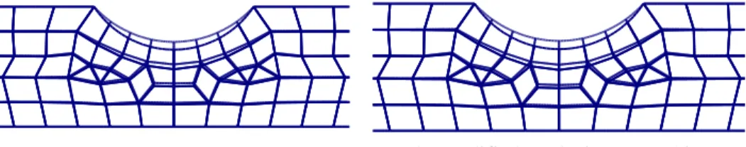
Figure 2: Comparaison of Four Different Laplacian Smoothing Schemes .
Applications of several relocation schemes are presented in figures 2a-b-c-d. The velocity fields are relative to a modification of the circular notch curvature (with a relative perturbation of 10 ). The free mesh-4 has been generated by an offset generator and the drawn node displacements are amplified by a 10 factor.4 The perturbated meshes (in dot lines) of figures 2 are yielded when applying respectively Laplacian smoothing, modified Laplacian smoothing, isoparametric Laplacian and inverse power (1/L with p=2)p schemes. This example shows hat the deformed mesh is very similar to the original one, preserving the mesh quality. The boundary modification yields a deep mesh flow. In the present case, the smallest depth of perturbation is given by the isoparametric Laplacian smoothing while the power scheme diffuses it far away because of the increased rigidity of the small triangular elements. Nevertheless, sensitivity analysis of displacements and stress reveals closed results.
Other numerical tests have been realized to compare relocation schemes with other velocity field methods. In fact, there is no contradiction between smoothing and transfinite velocity field since transfinite remeshing can be regarded as a perfect Laplacian smoothing of the regular mesh in the intrinsic coordinates system. On the other hand, the local approach (where only the outer layer of nodes are relocated while the inner nodes remain unchanged) can be considered as a limit case of Laplacian smoothing technique when the depth of mesh flow is reduced to the outer elements. Despite its simplicity, studies in Ref.7 demonstrated that this technique exhibited a degradation of sensitivity analysis quality resulting in a slower convergence when applied to complicated problems. Finally, like natural methods, Laplacian smoothing is related to a physical phenomenon as steady state thermal distribution; it could also be retrieved from linear elasticity equation if uncoupling displacements are assumed. Ref.7 showed that assumption gives similar results but smoothing is much more inexpensive than additional F.E. analysis.
Figure 3: Optimization of a Torque Arm .
Now this new tool is fully integrated in the OPTI-SAMCEF package to handle free unstructured meshes. Its ability to handle real-life problems is illustrated by the well known application of a torque arm shape optimization (see Ref.13, 2, 7). The weight of this rear automotive torque arm is to be minimized while the maximum stress is limited to 80000 N/cm . Eight design variables describe the outline of the arm as an2 assembly of straight lines and circle arcs with tangent conditions. An offset free mesh generator was selected and applied at each iteration to maintain mesh quality with the same mesh density. Figure 3 shows the initial and final shapes (after 8 iterations with CONLIN optimizer ).2
5. CONCLUSIONS.
In order to take into account the new free mesh generators in a modern shape optimization tool, the authors have turned their attention towards smoothing procedures to solve the mesh flow problem. The research led to create a procedure based on applying smoothing to the increments of node position after perturbating the outline definition. Provided the velocity field exhibits a sufficient depth of perturbation propagation in the mesh, the tested relocation schemes have revealed robust and reliable. In addition of its efficiency and reliability, sensitivity analysis is also inexpensive since smoothing is formulated as the repeated solution of a scalar problem. These procedures are now integrated in the commercially supported software OPTI-SAMCEF. After application of smoothing to 2-D problems, the method is now being integrated and tested in 3-D problems. Even though applications seem to be heavier, encouraging results are expected.
REFERENCES:
1. Braibant, V. and Fleury, C.: "Shape optimal design using B-splines", Computer Methods in Applied Mechanics and Engineering , vol. 44, 1984, pp 247-267.
2. Braibant, V. and Fleury, C.: "An approximation-concepts approach to shape optimal design", Computer Methods in Applied Mechanics and Engineering , vol. 53, 1985, pp 119-148.
3. Braibant, V. and Morelle, P.: "Shape optimal design and free mesh generation", Structural Optimization, vol 2, 1990, pp 223-231.
4. Morelle, P., Duysinx, P., Fleury, C.: "CAD/FEM coupling in shape optimization", FEM'92 IKOSS Congress, Baden-Baden, Germany, November 1992.
5. Belgundu, A. and Rajan, S.: "A shape optimization approach based on natural design variables and shape functions", Computer Methods in Applied Mechanics and Engineering, 1988, pp 87-106.
6. Yao, T.S., Choi, K.K.: "3-D shape optimal design and automatic finite element regriding", International Journal of Numerical Methods in Engineering , vol. 28, 1989, pp 369-384.
7. Zhang, W. H.: "Calcul des sensibilités et optimisation de forme par la méthode des éléments finis", Ph. D. dissertation, University of Liège, Applied Sciences Faculty, 1991, (In French).
8. Beckers, P.: "Recent developments in shape sensitivity analysis: the physical approach", Engineering Optimization, vol 18, 1991, pp 67-78.
9. Kibsgaard, S.: "Sensitivity analysis - The basis for optimization", International Journal of Numerical Methods in Engineering , vol. 34, 1992, pp 901-932.
10.Herrmann, L.R.: "Laplacian-isoparametric grid generation scheme", J. Engng Mech. Div., ASCE, vol. 102, 1976, pp 749-756.
11. Robinson, B., Batina, J. and Yang, H.: "Aeroelastic analysis of wings using Euler equations with deforming mesh", Journal of Aircraft, vol 28, nE11, November 1991.
12. Diaz, A., Kikuchi, N. and Taylor, J.: "A method of grid optimization for finite element methods", Computer Methods in Applied Mechanics and Engineering, vol.41, 1983, pp 29-45.
13. Bennet, J.A. and Botkin, M.E.: "Shape optimization of two-dimensional structures with geometric problem description an adaptative mesh refinement", presented at AIAA/ASME/ASCE/AMS Structures, Structural Dynamics and Material Conference, Lake Tahoe, Nevada, 1983.
SENSITIVITY ANALYSIS WITH UNSTRUCTURED FREE MESH GENERATORS
IN 2-D AND 3-D SHAPE OPTIMIZATION.
P. Duysinx, W.H. Zhang, C. Fleury.
Aerospace Laboratory, LTAS, University of Liège B-4000 LIEGE, BELGIUM.
ABSTRACT.
Shape optimization has reached sufficient maturity to handle real-life problems in industrial environment. However, shape optimization packages have now to consider new progress in mesh generators and have to integrate these new capabilities to take full benefits from the use of free unstructured meshes in realistic industrial optimization.
To take into account those interesting new tools, the main difficulty relies in the velocity field determination during sensitivity analysis. From all the possible velocity field procedures, the authors' experience in applying smoothing techniques is presented. First it is shown that smoothing techniques satisfy fundamental requirements to carry out successfully the sensitivity analysis task for unstructured meshes with success. Boundary perturbations are transmitted to the inner mesh through a smoothing criterion. It is explained how smoothing can be used to evaluate velocity fields in a cheap and simple way while guarantying reliability, efficiency and precision. A wide range of smoothing procedures (pure Laplacian methods, length weighted smoothing or relocation based on finite element error criteria) are presented. Original improvements and modifications are presented to deal with refined meshes, F.E. errors information, etc... . Smoothing procedures are also compared with other velocity field approaches to provide an analysis of advantages and drawbacks of the method.
Extensions from 2-D planar problems to 3-D shell and volume shape optimization are then discussed. Finally, applications of smoothing procedures in the commercial optimization package OPTI-SAMCEF are described. And several practical examples are provided to illustrate the proposed approach.