Technology researchers and makes it freely available over the web where possible.
This is an author-deposited version published in: https://sam.ensam.eu Handle ID: .http://hdl.handle.net/10985/6794
To cite this version :
Paul SANDULESCU, Fabien MEINGUET, Xavier KESTELYN, Eric SEMAIL, Antoine BRUYERE -Flux-weakening operation of open-end winding drive integrating a cost effective high-power charger - IET Electrical Systems in Transportation - Vol. 3, n°1, p.26 - 2013
Flux-weakening operation of open-end winding drive
integrating a cost effective high-power charger
Journal: IET Electrical Systems in Transportation
Manuscript ID: EST-2012-0026.R1
Manuscript Type: Research Paper
Date Submitted by the Author: 25-Sep-2012
Complete List of Authors: SANDULESCU, Alexandru; ARTS ET METIERS PARISTECH, EEA/L2EP Meinguet, Fabien; ARTS ET METIERS PARISTECH, EEA/L2EP
Kestelyn, Xavier; ARTS ET METIERS PARISTECH, EEA/L2EP Semail, Eric; arts et metiers paristech, electrical engineering
Keyword:
AC MOTOR DRIVES, AUTOMOTIVE ELECTRICAL SYSTEMS/TECHNOLOGIES, CLOSED LOOP SYSTEMS, ELECTRIC VEHICLES, PERMANENT MAGNET MACHINES, TORQUE CONTROL
Abstract:
In this paper, a three-phase drive with a six-leg Voltage Source Inverter (VSI) and an open-end winding
Interior Permanent Magnet Synchronous Machine (IPMSM) designed for the traction of an electric vehicle is studied
in flux-weakening operation. The topology allows the functionality of a high power charger to be obtained, without
adding any other supplementary power devices. On the other hand, since there are three independent currents, the
control structure has to handle not only the two dq current components but also a zero-sequence current. If neglected,
in comparison with wye-coupled three-phase drive, this zero-sequence component can cause a higher maximum peak
value of the phase currents, additional stator Joule losses, torque ripple, inverter voltage saturation and IGBT
oversizing. The proposed control strategy consists in adapting a conventional method used for wye-connected
machines particularly in flux-weakening operation. This strategy allows the closed-loop control of the zero-sequence
current to be maintained in the whole speed range and therefore inverter saturation is avoided. Simulations and
experimental results are presented and analyzed.
1 Introduction
Permanent magnet synchronous machines (PMSMs) have been demonstrated to be a good solution for a wide range of applications because of their high power to weight ratio, compactness, high efficiency and ease of control [1]. In the past decade, many configurations of PMSMs have been proposed, e.g. in terms of magnet positioning [2], [3] winding configurations [4] and topologies of the VSI [5].
In order to increase the torque output and the fault tolerance of the drive, topologies with individual drive units for each phase have been widely investigated [6] – [9]. Among these topologies is the cascaded inverter or open-end winding topology (depicted in Figure 1). In [10] and [11], it is shown that this topology is equivalent to a three-level VSI in terms of available
Paul Sandulescu
(1), Fabien Meinguet
(1), Xavier Kestelyn
(1), Eric Semail
(1), A. Bruyere
(2)(
1) Ecole Nationale Supérieure d’Arts et Métiers, 8, Boulevard Louis XIV, 59046 Lille, FRANCE phone :
+330320622210-2254; e-mail: Alexandru-Paul.SANDULESCU-6@etudiants.ensam.eu
(2) Valeo Engine and Electrical Systems VEES 14, avenue des Béguines, 95800 Cergy Saint-Christophe, FRANCE
Flux-weakening operation of open-end winding drive
integrating a cost effective high-power charger
voltage vectors. Although the number of switching components is twice the number used for the classical wye-configuration, the topology allows the application of the full DC-link voltage across the phases and increases base speed and power output, as presented in [5]. In spite of these advantages, the additional costs linked to the three supplementary power legs curbs the
industrial development of the topology, especially for large scale production such as car manufacturing.
In the context of an electric vehicle with a metric horsepower of around 40 to 50 kW, this drawback can be removed by adding a high-power charger functionality (>40kW) to the traction functionality, as described in [12] - [15]. No supplementary power device has to be added to achieve the power charger functionality. It is obtained through the addition of three supplementary outputs for electric grid connection (Figure 1). This is an advantage over [16] where the use of additional high-power contactors is obligatory. In addition, the ease of access and control of all three windings of the machine makes possible not only single phase low-power charging as in [17], [18], [19] but also three-phase high-power fast charging, thus increasing the availability of the electric vehicle. The benefit of a rotor to stator magnetic decoupling in charging mode is also very important as there is no torque generation on the motor shaft due to the split-phase architecture. Compared to [20], where the use of a clutch is needed, the proposed solution is advantageous. With this new charging functionality, obtained without any other costly power device, the aforementioned drawbacks of the open-end winding topology completely disappear.
Among open-end winding topologies, two kinds must be distinguished: in the first family there are two independent DC links and in the second family only one DC link is reported in the literature. In the first configuration [21], no zero-sequence component can circulate. Therefore, the control is basically the same as for wye-connected machines [22] - [24] and classical over-modulation techniques are applied [21].
For the system under study, the second configuration has been chosen in order to implement the functionality of a high power charger with a single battery. In this case, three currents instead of two have to be managed as a zero-sequence current appears.
For the cascaded inverter topology with a single DC-link, dedicated control strategies have been developed in Maximum Torque Per Ampere (MTPA) operation in order to cancel the zero-sequence current component. Solutions have been shown in [11] and [25], in which VSI control strategies have been addressed in order to cancel the high frequency zero-sequence current. In [11], [26] and [27], the average zero-sequence component is considered as one additional Degree Of Freedom (DOF) that has to be managed. Therefore, an independent zero-sequence control scheme is developed and the third harmonic current is controlled.
In the flux-weakening region using Maximum Torque Per Voltage (MTPV) [28], the operation is more difficult. Under saturation conditions, in addition to the first harmonic, the zero-sequence harmonics have to be considered. Therefore, a flux-weakening strategy that can preserve the controllability of the system and avoid VSI saturation is obligatory. For the single DC-link topology under study, this problem has not been addressed in previous papers.
In this paper, a flux-weakening algorithm for an open-end winding machine associated with a six-leg VSI is proposed. The algorithm is oriented to manage the additional degree of freedom, which is the zero-sequence component.
The paper is developed in four sections, as follows:
• The electrical machine model is presented and the equations are established.
• A flux-weakening solution is presented and simulated on a 3-phase wye-connected machine for comparison purposes. • Problems using the classical flux-weakening solutions are identified for a three-phase open-end winding machine, and a
solution is presented. Simulations are carried out and results are presented. • Experimental results are shown in section 4.
2 Drive model
The system under consideration is depicted in Figure 1. The voltage equations of the machine are expressed in the abc reference frame, and yield the following expression:
+ + = c b a c b a c b a s c b a E E E I I I L M M M L M M M L dt d I I I R V V V (1)
where Rs is the stator resistance, L and M are the self- and mutual inductances, Vx, Ix, Ex are the x - phase voltage, the x - phase
current and the electromotive force (emf) induced by the permanent magnets in the x - phase respectively x∈{a,b,c}. It is
assumed that the emf harmonic components consist of the fundamental and third-harmonic components and that higher-order harmonic components are negligible.
The model of the machine expressed in the stator and in the rotor reference frames is obtained by applying the Concordia and rotation transformations successively defined by:
[
X]
[ ][
C Xabc]
3 2 0αβ = (2)[
X0dq]
=[ ]
R[
X0αβ]
(3)with transformation matrices given by:
[ ]
− − − = 2 3 2 3 0 2 1 2 1 1 2 1 2 1 2 1 C (4)[ ]
− = e e e e R θ θ θ θ cos sin 0 sin cos 0 0 0 1 (5)The quantity X can be a vector of currents, voltages or fluxes and θe is the electrical position of the rotor. Applying the
transformations (2) and (3) to the system (1) gives:
+ + = q d q d q d q d s q d E E E I I I L L L dt d I I I R V V V0 0 0 0 0 0 0 0 0 0 0 (6) with + − = 1 , 0 (3 ) M d d q q e e q d I L I L e E E E ψ θ ω (7)
where ωe is the electrical pulsation, ΨM,1 the magnitude of the fundamental component of the flux linkage due to the permanent
magnets, Ld and Lq the d- and q-axis inductances respectively and e(3θe ) is a sinusoidal function of 3θe.
In (6) the classical two-dimensional dq subspace and one additional subspace responsible for the zero-sequence components are identified. For three-phase wye-connected machines, the zero-sequence current subspace is usually neglected, as current harmonics which are multiples of three (k x 3, k=0, 1, 2,…) are reduced to zero due to the electrical star connection.
The torque equation is given by:
(
)
(
)
(
,1L
L
I
I
e
(
3
)
I
0)
N
T
=
ppψ
M+
d−
q d q+
θ
e (8) whereN
pp is the number of pole pairs.The machine has a non-salient pole characteristic. For a zero-sequence current control that imposes a null zero-sequence current, the torque equation simplifies to:
q M pp
I
N
T
=
ψ
,1 (9)3 Flux-weakening scheme
As speed increases, the emf can reach values that saturate the VSI. It is possible to go beyond the base speed, defined as the maximum speed at rated torque, by applying a flux-weakening strategy [29]. Thus, in order to exceed the base speed, the instantaneous voltage and current reference values in the abc reference frame have to satisfy:
max *
V
max
* I
Ia ≤ Ib* ≤Imax Ic* ≤Imax (11)
where Imax is the peak current limit due to machine thermal constraints and Vmax is the maximum voltage limit that can certify a
non-saturated state of the VSI. In what follows, the choice of the voltage limit value which depends on the topology of the machine structure will be investigated.
3.1
Flux-weakening scheme for a wye-connected PMSM
In this section, the flux-weakening techniques usually carried out for classical wye-coupled three-phase machines (the dq machine) are investigated.
Two types of VSI saturation management strategies are known, under the names of over-modulation and flux-weakening respectively. These strategies are complementary.
The over-modulation method is widely used for wye-connected three-phase machines as it can increase the voltage limit in the natural reference frame up to:
3
maxwye DC
V
V = (12)
thus a 15.5% increase in voltage limit. This is done by injecting third harmonic voltages in phase with the fundamental voltages generated by the current control loop [30]. A simple solution for calculating the necessary over-modulation zero-sequence voltage is presented in [31]. For a three-phase star-connected machine, it simplifies to:
2 ) , , min( ) , , max( * * * * * * * 0 Va Vb Vc Va Vb Vc V =− + (13) * 0 * * *
V
V
V
abc=
abc+
(14)The over-modulation strategy increases the base speed value thanks to a better use of the DC-link voltage, but it does not allow the operation of the drive above this base speed. Moreover, it is the wye-coupling connection that prevents the generation of a third-harmonic current despite the injection of a third-harmonic voltage.
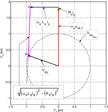
The over-modulation strategy is followed by flux-weakening, which is widespread in the literature and can be implemented in many ways. One approach is the feed-forward solution [32] based on the electrical machine model (6). In this paper, this solution is referred to as “Model Based Flux-Weakening” (MB_FW). It is stated in [32] that the influence of the resistive voltage drop is important and should be accounted for. Hence, the authors of [32] propose a feed-forward algorithm based on the analysis of the voltage limit circle in the dq current plane. However, a simpler analysis presented in this paper can be conducted in the dq voltage plane, as presented in Figure 2. An analytical solution for the current references (Id*, Iq*) is thus obtained. The calculation
intersection between the straight line (AB) (15a) and the voltage limit circle defined by the radius Vdq max (15b). The solution Id* of
the resulting second-order equation in Vd is given by:
=
+
+
+
+
=
)
15
(
)
15
(
2 max 2 2 * 2 * 1 ,b
V
V
V
a
R
I
L
L
I
R
V
R
L
V
dq q d s q q d e q s M e d s d e qω
ψ
ω
ω
s q q e s d d s dq s sR
I
L
x
I
c
V
x
V
b
dx
cx
* * 2 max 2 2)
15
(
with
=
⇒
=
+
ω
=
+
+
⇒
(15) where c d xs 2 ∆ + − = ;∆=4(Vdq2,maxc−b2), 2 3 2 2 3 max , DC dq V V = , s d e R L a=ω , s q q d e q s M eR
I
L
L
I
R
b
* 2 * 1 ,ω
ψ
ω
+
+
=
, c=1 a+ 2, ab d=2In case the current limit is reached, a dynamic saturation of Iq* is implemented: 2 * 2 max , * d dq q I I I = − (16)
with ,max max
2 3
I
Idq = due to the Concordia transformation (2).
Considering the parameter sensitivity of the aforementioned solution, an Integrator-Based Flux-Weakening (IB_FW) strategy, as presented in [23], [33], is combined with the analytical solution. Thus, this allows the benefits of both strategies IB_FW and
MB_FW to be combined.
In this case, the flux-weakening scheme for a wye-connected three-phase machine is presented in Figure 3. Notice that between the dq frame voltage limit value Vdq max and the DC-link VDC there is only a factor of
2 1
after the Concordia transformation coefficient is applied.
For the dq current control, a PI structure and feed-forward compensation are used. The feed-forward compensation comprises the emf and the cross coupling terms.
Simulation parameters are presented in Table 1. In Figure 4 the emf for one phase with the first and third harmonic components is shown, considering the parameters in Table 1. The simulation results of the flux-weakening scheme are shown in Figure 5. For the simulations, an average model of the VSI is considered.
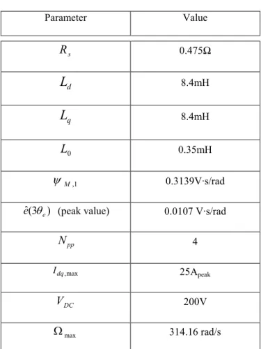
Table 1 Simulation parameters Parameter Value s
R
0.475Ω dL
8.4mH qL
8.4mH 0L
0.35mH 1 , Mψ
0.3139V·s/rad ) 3 ( ˆ ee
θ
(peak value) 0.0107 V·s/radpp
N
4 max , dq I 25Apeak DCV
200V maxΩ
314.16 rad/sThe simulation is performed for a speed ramp that lasts 2.5 s and for a torque reference of 1 pu. The pu value of the mechanical speed is calculated using
[ ]
max Ω
Ω =
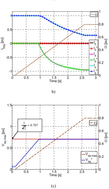
Ω pu . In Figure 5 a) the abc frame modulation functions are shown and the effects of the over-modulation strategy are perceived through the presence of the zero-sequence harmonic components. The 0dq currents are presented in Figure 5 b). Due to over-modulation, the flux-weakening strategy starts at t=0.93 seconds at a base speed of 0.27pu. It is noticed that the sequence current is null, even though the over-modulation method injects a zero-sequence voltage into the machine. This is a well known property of the wye-connection. In Figure 5 c) the representation of the voltage in the dq frame is shown. At t=0.93 seconds, the dq reference voltage Vdq* reaches the maximum extended voltage limit
which includes the 15.5 % voltage gain (Figure 5c)), equal to 1/√2 when a normalization with VDC is used. The voltage limit is
constant throughout the entire speed ramp.
3.2 Classical flux-weakening scheme applied to open-end winding PMSM
Open-end winding configuration requires the modification of the classical flux-weakening strategy. The first modification regards the current, where a Joule losses limitation is proposed. Through consideration of the electrical parameters given in Table 1, the small resistance value and the low zero-sequence inductance compared with the dq-axis inductance values can be
observed. In this case, depending on the control structure, the zero-sequence current can easily circulate in the machine. Because of the sinusoidal nature of the zero-sequence current that can be generated, an additional limit on the maximum q-axis current is taken into account as follows:
2 0 2 * 2 max , * RMS d dq q
I
I
I
I
=
−
−
(17) The voltage limitation used for the classical three-phase wye-connected machine is no longer valid for the proposed topology. For the H-bridge topology, with respect to the transistor states, the voltage levels on one phase are: -VDC, 0 or +VDC. Therefore,the full DC-link voltage can be applied to the winding of the machine, which is twice the value used in the case of a wye-connected machine. Hence:
DC wye V V V 3 2 2 max max = = (18) For the parameters used in the previous simulation, the results are shown in Figure 6.
In Figure 6 the zero-sequence current reaches high values due to the open loop control of the zero-sequence voltage. Using (6), the zero-sequence current can be expressed by:
( )
(
)
s K E V s I 0 0 0 * 0 0 = − 1+τ (19) where s R K0 = 1 and s R L0 0 = τThe machine parameters have a substantial influence on the resulting current, as it can be deduced from (19). As speed increases, the over-modulation technique used classically to extend the voltage limit of the flux weakening algorithm is no longer suitable for the open-end drive topology and as a result, a zero-sequence current is generated.
In order to maintain the control of the zero-sequence current, different control strategies can be used [26], [27]. Using I0*=0
strategy, stator Joule losses and torque ripple is minimized but the use of a current control loop is obligatory. As the over-modulation method cannot be used and a zero-sequence current control strategy is necessary, a new voltage limit has to be imposed in order for the flux-weakening algorithm to be implemented. The new voltage limit has to take into account the constraints of the new zero-sequence current control loop and has to fulfill (10) as well. The flux-weakening algorithm will be influenced by the new voltage limit and the current reference will be changed accordingly.
3.3 Modified flux-weakening scheme applied to open-end winding PMSM
As shown in Figure 6 and presented in [26], the zero-sequence current control loop can no longer be neglected as in the case of wye-connected machines.
In Figure 7 a) the zero-sequence current control loop is illustrated. The control loop comprises zero-sequence emf compensation and a classical PI regulator. The PI output is useful in the case of parameter uncertainty or non-linearity of the magnetic circuit.
In order to impose a null zero-sequence current, considering a perfectly decoupled system as presented in (6), one can infer that: ce zerosequen PI e ee V V0* =
ω
(3θ
)+ (20)In Figure 7a) the flux-weakening scheme for the open-end winding machine is also presented. Considering the model in (6) and for a zero-sequence current reference set to zero, the control loop will imply the use of the thirdharmonic voltage component in order to compensate the zero-sequence emf required in (20). In addition, no coupling exists between the zero-sequence subspace and the dq subspace if the VSI is not saturated. As speed increases, the saturation of the VSI will lead to a coupling of the two separate subspaces. Depending on the machine parameters, the voltage imposed by the zero-sequence control loop may place the VSI in a saturation state even if the classical dq voltage limit (18) is not reached. In this case, to guarantee the controllability of the zero-sequence current, a new voltage limit for the dq frame is determined which ensures that at any time and for all allowed torque references Vx≤VDC.
Concerning the calculation of the new voltage limit in the dq reference frame (Vdq max), the zero-sequence voltage reference V0*
has to be taken into account. Resolution of the equation Vx(t)=VDC, with x=a for example, allows the maximum peak value of
the dq voltage reference to be found. This ensures the non-saturation of the VSI:
) 3 ˆ ( 2 3 0* max , V V Vdq = DC− (21)
withVˆ0*expressing the envelope of V0*. The algorithm is summarized in Figure 7b). First, the envelope of the zero-sequence
voltage reference generated by the zero-sequence control loop is estimated. Next, the dq voltage limit is calculated using (21). Finally, the flux-weakening algorithm will generate the current references using the new calculated voltage limit.
Simulation results are provided in Figure 8 using the same simulation conditions as for the examples shown previously. In Figure 8 a) it is noticed that the three voltage references are maintained within the limits of the VSI. The three abc modulating signals consist of the first and the third harmonic components. In this case, the third harmonic component is generated by the zero-sequence current control loop and not by the over-modulation strategy. Regarding Figure 8 b) and Figure 5 b) it is noticed that the flux-weakening current Id is smaller compared with the classical wye-configuration. This has a positive
impact on the torque to speed ratio, as shown in Figure 9. In Figure 8 c) the zero-sequence voltage and the envelope are presented, reaching 0.053 pu at steady state. Even though the zero-sequence voltage compensation necessary in (20) can reduce the utilization ratio of the VSI, the base speed has increased noticeably, as presented in Figure 9 (0.48 pu compared to 0.27 pu
for the wye-connected case). Extending the analysis of the base speed, in Figure 9, the torque is shown as a function of the speed when the flux-weakening algorithm is used for the wye-connected machine without the over-modulation strategy. For the same current Is, the ratio between the base speed for the open-end connection case and the base speed for the wye-connection case is
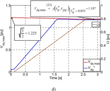
roughly 2. The small difference is due to the sensitivity to resistive voltage drop which is different for the two topologies. In Figure 8 d) the voltage reference in the dq frame is presented and compared with the actual voltage limit calculated in (21). At t=1.51 seconds, the voltage limit in the dq frame is reached and, as speed increases, the dq voltage limit is proportionally adjusted with respect to the zero-sequence voltage injected by the zero-sequence control loop. Reformulating (21) reveals that the maximal dq voltage limit is equal to:
3 lim * 0 max
3
1
2
3
H dq DC DC dqV
C
V
V
V
V
=
−
=
(22) where Vdqlim is the dq voltage limit that accounts for the fundamental component and CH3 is an online computed coefficient thataccounts for the third harmonic utilization ratio relating to the chosen zero-sequence current strategy (in our case I0*=0). For
example, in Figure 8 d), at t=3 seconds, CH3 reaches 0.969 and thus, the normalized maximal dq voltage limit falls to 1.187. This
drop of approximately 3% of the maximal dq voltage limit is due to the small sequence voltage demand of the zero-sequence control loop.
Figure 10 presents the impact of the emf harmonic component on the base speed. For the case under study, the third-harmonic ratio is 2.5 % resulting in a base speed decrease of 2.02 % in comparison with the case where no emf third-third-harmonic component is present. For different electrical machines, considering the same electrical parameters from Table 1, but for a higher ratio of emf third-harmonic component, the impact on the base speed is more visible.
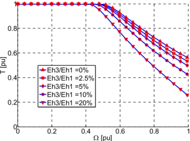
Figure 11 investigates the consequence of the emf third-harmonic component with respect to the maximal dq voltage limit. Figure 12 presents the impact of the emf third-harmonic component on torque for speed values ranging from 0 to Ωmax. All test
results are shown for 1 pu torque reference and the current and voltage limitations apply. For each curve, above base speed, the torque value decreases as more d-axis current is requested by the flux-weakening algorithm. In addition, for a zero-sequence current control equal to I0*=0 and for increasing values of the emf third-harmonic component, the torque to speed ratio is less
efficient, leading to reduced torque to speed envelopes.
4 Experimental Results
In this section, experimental tests were carried out on a 5kW, three-phase open-end winding machine with the electrical characteristics presented in Table 1. The machine used is industry designed and manufactured for traction application purposes, and therefore the windings have been adapted to support the battery charger functionality. The electrical machine is connected to
a six-leg VSI, controlled by an OPAL-RT digital real-time simulator. The PWM and control-loop frequencies are set to 10 kHz. Concordia transformation and rotation, current filters and the detection of the zero-sequence voltage envelope are deployed on a Xilinx Spartan 3A FPGA chipset embedded in the digital real-time simulator with a sampling frequency of 1 MHz. The load machine is speed controlled, while the open-end winding machine is torque controlled. As a result, the experimental tests on the open-end winding PMSM are similar to a vehicle behavior scenario.
The test consists in imposing a 1 pu torque reference to the three-phase open-end winding machine while applying a speed ramp using the load machine. The test aims to obtain similar results to those presented in the simulation section (Figure 8).
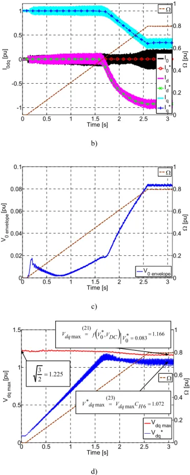
In this test, the dq voltage limit is calculated using (21) and equation (20) is satisfied. Results are presented in Figure 14. 0dq current waveforms are similar to those obtained during the simulations. For the d-axis current, simulations show a lower absolute value when compared with that obtained by experiment. As a consequence, the experimental q-axis current is smaller, due to the current limitation (17). The base speed remains approximately the same relative to the simulation results for the open-end connection topology.
Through the experimental results it appears that a second phenomenon (fifth and seventh harmonics of voltage) should be taken into account for further increasing the performances of the drive. In Figure 14 b) and Figure 15, the dq currents show the presence of a sixthharmonic while the zero-sequence current is affected by the thirdharmonic component. These harmonics are due to the presence of terms with harmonic order of 2θe and 4θe in the real inductance matrix presented in (1). These terms are
responsible for non-zero cross-coupling in the inductance matrix presented in (6). These coupling terms are now present in the form of sixth and third harmonic inductances in the 0dq reference frames. In addition, the emf is affected by fifthand seventh harmonics since the machine is designed with a concentrated 12slots/8poles winding [34] in order to ease the control of the high-power charger when this functionality is used. Therefore, sixth harmonic voltages are detected in the dq reference voltages (“noise” in Figure 14d)). For this reason, a coefficient has been added, to modify the dq voltage limit, as the control focused only on first and third harmonic components. From (21) and (22), it follows that the adapted maximal dq voltage limit is:
lim 3 6 max , 6 * max , H dq H H dq dq C V C C V V = = (23) where CH6 represents the fifth and seventh harmonic quantification ratio, set at a constant value of 0.92 on the basis of
experiments. The CH6 coefficient will force the flux-weakening algorithm to generate a higher absolute value of the d-axis
current reference compared to the simulation case. Nevertheless, there is a major difference between the impact of the third harmonic component and fifth and seventh harmonic components of the voltage and the emf. The reason is that the inductances
considered are not the same: L0 for the third harmonic and approximately 2
q d L
L +
the ratio is high ( 24 2 0 ≅ + L L Ld q
for the experimental machine). As a consequence, for the same amplitude of voltage variation, the
associated variation of current is roughly in the same high ratio. The sensitivity to third harmonic variation is much higher than for the fifth and seventh harmonics. It must be noted also that the impact of fifth and seventh harmonics is not specific to the open-winding configuration.
At time t=1.51 seconds (Figure 14 d)), the voltage limit is reached. The flux-weakening algorithm generates the necessary voltage references according to (10), (17), (21) and (23). In Figure 14 c) the result of the envelope detector is given. The V0
envelope is primarily affected by the zero-sequence PI output and less by the zero-sequence emf compensation, since in the
experimental machine the emf third harmonic is weak (see Figure 11). From t=1.51 seconds to the end of the speed ramp, the envelope detection algorithm will influence the voltage limit calculation, as seen in Figure 14 d). For example, at t=3 seconds, the zero-sequence envelope detector provides a pu value of 0.083. From (22) and (23) it follows that the mean of the dq voltage reference value should be at 1.07, confirming (23). From 0 to 0.8 pu mechanical speed, the calculated voltage limit will decrease by approximately 5%. The difference is small in our experimental case, as this open-end machine has been designed with a low amount of emf third harmonic component (2.5%). For a higher Eh3/Eh1 ratio, the dq voltage drop can be greater (according to
figure 11, 33% at 1 pu speed for Eh3/Eh1=20%).
5 Conclusion
This paper has addressed the problem of flux-weakening operation for a specific topology: a six-leg VSI and an open-end winding machine designed for traction of a full electric vehicle. Its main interest is to provide a high-power charger functionality for electric vehicles without adding any power components. Although the cost of this topology is higher than that of a classical three-leg VSI with a wye-coupled machine, the addition of the high-power charger functionality largely compensates this initial drawback: the global cost of the combined functionalities is lower. Nevertheless, the six-leg VSI configuration requires specific attentions, due to the presence of one supplemental DOF – the zero-sequence component.
The inductance value associated with the zero-sequence variables is generally low, consequently, a control is required to avoid high value zero-sequence currents. Moreover, these zero-sequence currents can induce torque pulsations in presence of emf third harmonic component.
As a consequence, a control loop is necessary in order to have a null zero-sequence current: zero-sequence voltages are then generated. As long as there is no VSI saturation, the third harmonic components are decoupled from the dq-frame components. However, when the flux-weakening region is reached, the maximum available value of the dq voltage decreases due to coupling between the two voltage subspaces defined by the zero-sequence and the dq-plane.
The paper has explored this problem, proposed a solution and verified it by simulation and then by experimental implementation.
For the experimental machine with a low emf third harmonic value (Eh3/Eh1=2.5%), the theoretical value of maximum
available voltage in the dq-plane Vdq max at 1 pu mechanical speed is 1.177VDC instead of 1.224VDC. This value can be compared
with the 0.707VDC obtained for a three-leg VSI wye-coupled machine with third-harmonic injection. As a consequence, the
constraint zero-sequence current will induce a small 3.9% loss of available voltage. It can be concluded that the machine has been well-designed as regards this problem since the associated impact is low.
For a machine with other Eh3/Eh1 ratio, the paper shows that the loss can be quite noticeable: for Eh3/Eh1= 20%, at 1 pu
mechanical speed the available voltage loss is near 33%.
Therefore, the study done in the paper is fundamental for the prediction range of the flux-weakening area.
Appendix
Symbol Quantity s R Stator resistance d L d axis inductance q L q axis inductance 0 L Zero-sequence inductance 1 , Mψ dq frame magnetic flux linkage
) 3 ( e
e θ Peak zero-sequence emf for one rad/s
pp
N
Number of pole pairsmax
I
abc frame peak currentmax ,
dq
I dq frame peak current
* 0
V Zero-sequence voltage reference
* dq
V dq frame voltage reference
max ,
dq
V dq frame peak voltage limit
max
DC
V DC-link voltage
max
Ω Maximal mechanical speed
Acknowledgment
Authors would like to thank to the French F.U.I. and VALEO for the support given to the SOFRACI project.
References
[1] Jahns, T.M., Kliman, G.B., Neumann, T.W.: ‘Interior Permanent-Magnet Synchronous Motors for Adjustable-Speed Drives’, IEEE Transactions on Industry Applications, 1986, IA-22(4), pp. 738-747.
[2] Scuiller F., Semail E., Charpentier J., Letellier P.: ‘Multi-criteria-based design approach of multi-phase permanent magnet
low-speed synchronous machines’, Electric Power Applications, IET 2009, 3, (2), pp. 102-110.
[3] Barcaro M., Bianchi N., Magnussen F.: ‘Permanent-Magnet Optimization in Permanent-Magnet-Assisted Synchronous Reluctance Motor for a Wide Constant-Power Speed Range’, IEEE Transactions on Industrial Electronics, 2012, 59, (6), pp.
2495-2502.
[4] Chong L., Rahman M.F., ‘Comparison of d- and q-axis Inductances in an IPM Machine with Integral-slot Distributed and Fractional-slot Concentrated Windings’. 18th International Conference on Electrical Machines (ICEM 2008), Vilamoura,
Portugal, September 2008, pp. 1-5.
[5] Welchko B.A., Nagashima J.M.: ‘The influence of topology selection on the design of EV/HEV propulsion systems’, IEEE Power Electronics Letters, 2003, 1, (2), pp. 36-40.
[6] Wang Y., Lipo T.A., Pan D.: ‘Half-Controlled-Converter-Fed Open-Winding Permanent Magnet Synchronous Generator for Wind Applications’. 14th International Power Electronics and Motion Control Conference (EPE-PEMC' 2010), Ohrid, Republic
of Macedonia, September. 2010, pp. T4-123-126.
[7] Wang Y., Lipo T.A., Pan D.: ‘Robust Operation of Double-Output AC Machine Drive’. 8th International Conference on Power
Electronics (ICPE 2011), Jeju, Korea, May-June 2011, pp. 140-144.
[8] Welchko B.A., Lipo T.A., Jahns T.M., Schulz S.E.: ‘Fault tolerant three-phase AC motor drive topologies: a comparison of features, cost, and limitations’, IEEE Transactions on Power Electronics, 2004, 19, (4), pp. 1108-1116.
[9] de Lillo L., Empringham L., Wheeler P.W., Khwan-On S., Gerada C., Othman M.N., et al.: ‘Multiphase Power Converter Drive for Fault-Tolerant Machine Development in Aerospace Applications’, IEEE Transactions on Industrial Electronics, 2010, 57,
(2), pp. 575-583.
[10] Corzine K.A., Sudhoff S.D., Whitcomb C.A.: ‘Performance characteristics of a cascaded two-level converter’, IEEE Transactions on Energy Conversion, 1999, 14, (3), pp. 433-439.
[11] Sandulescu P., Idkhajine L., Cense S., Colas F., Kestelyn X., Semail E., Bruyere A.: ‘FPGA Implementation of a General
Space Vector Approach on a 6-Leg Voltage Source Inverter’. 37th Annual Conference on IEEE Industrial Electronics Society
(IECON 2011), Melbourne, Australia, November 2011, pp.3482-3487.
[12] Lacroix S., Laboure E., Hilaret M.: ‘An Integrated Fast Battery Charger for Electric Vehicle’. IEEE Vehicle Power and Propulsion Conference (IEEE-VPPC 2010), Lille, France, September 2010, pp. 1-6.
[13] De-Sousa L., Bouchez B.: ‘Method and Electric Combined Device for Powering and Charging with Compensation Means’.
International Patent WO 2010/057893 A1
[14] De-Sousa L., Bouchez B., ‘Combined Electric Device for Powering and Charging’. International Patent WO 2010/057892 A1
[15] De Sousa L., Silvestre B., Bouchez B.: ‘A combined multiphase electric drive and fast battery charger for Electric Vehicles’. IEEE Vehicle Power and Propulsion Conference (IEEE-VPPC 2010), Lille, France, September 2010, pp. 1-6.
[16] Stancu C., Hiti S., Mundt E.: ‘Mobile electric power for medium and heavy duty hybrid electric vehicles’, IEEE 35th Annual Power Electronics Specialists Conference, Aachen, Germany, 2004, (1), pp. 228-234.
[17] Sul S.K., Lee S.J.: ‘An integral battery charger for four-wheel drive electric vehicle’, IEEE Transactions on Industry Applications, 1995, 31, (5), pp. 1096-1099.
[18] Solero L.: ‘Nonconventional on-board charger for electric vehicle propulsion batteries’, IEEE Transactions on Vehicular Technology, 2001, 50, (1), pp. 144-149.
[19] Shi L., Meintz A., Ferdowsi M.: ‘Single-phase bidirectional AC-DC converters for plug-in hybrid electric vehicle applications’,
IEEE Vehicle Power and Propulsion Conference (VPPC '08), Harbin, Hei Longjiang, China, September 2008, pp. 1-5.
[20] Haghbin S., Lundmark S., Alakula M., Carlson O.: ‘An Isolated High-Power Integrated Charger in Electrified-Vehicle Applications’, IEEE Transactions on Vehicular Technology, 2011, 60, (9), pp. 4115-4126.
[21] Sul S.K., Kwak M.S.: ‘Flux Weakening Control of an Open Winding Machine with Isolated Dual Inverters’. IEEE Industry Applications Conference, New Orleans, LA, September 2007, pp. 251-255.
[22] Kwon Y-C., Kim S., Sul S.K.: ‘Voltage Feedback Current Control Scheme for Improved Transient Performance of Permanent Magnet Synchronous Machine Drives’, IEEE Transactions on Industrial Electronics, 2012, 59, (9), pp. 3373-3382.
[23] Harnefors L., Pietilainen K., Gertmar L.: ‘Torque-maximizing field-weakening control: design, analysis, and parameter
selection’, IEEE Transactions on Industrial Electronics, 2001, 48, (1), pp. 161-168.
[24] Liu H., Zhu Z.Q., Mohamed E., Yongling Fu, Xiaoye Qi.: ‘Flux-Weakening Control of Nonsalient Pole PMSM Having Large Winding Inductance, Accounting for Resistive Voltage Drop and Inverter Nonlinearities’, IEEE Transactions on Power
Electronics, 2012, 27, (2), pp. 942-952.
[25] Baiju M.R, Mohapatra K.K., Kanchan R.S., Gopakumar K.: ‘A dual two-level inverter scheme with common mode voltage
elimination for an induction motor drive’, IEEE Transactions on Power Electronics, 2004, 19, (3), pp. 794-805.
[26] Bruyère A., De Sousa L., Bouchez B., Sandulescu P., Kestelyn X., Semail E.: ‘A multiphase traction/fast-battery-charger drive for electric or plug-in hybrid vehicles: Solutions for control in traction mode’. Vehicle Power and Propulsion
[27] Meinguet F., Semail E., Gyselinck J.: ‘Enhanced control of a PMSM supplied by a four-leg voltage source inverter using the
homopolar torque’. 18th International Conference on Electrical Machines (ICEM 2008), Vilamoura, Portugal, September
2008, pp. 1-6.
[28] Yoon Y.D., Lee W.J., Sul S.K.: ‘New flux weakening control for high saliency interior permanent magnet synchronous machine without any tables’. European Conference on Power Electronics and Applications (EPE 2007), Aalborg, Denmark,
September 2007, pp.1-7.
[29] Vas P.: ‘Sensorless vector and direct torque control’ (Oxford Science Publications, 1998).
[30] Hava A.M., Kerkman R.J., Lipo T.A.: ‘Carrier-based PWM-VSI overmodulation strategies: analysis, comparison, and design’, IEEE Transactions on Power Electronics, 1998, 13, (4), pp. 674-689.
[31] Blasko V.: ‘A Hybrid PWM Strategy Combining modified technique of the Space Vector PWM’. Proc. IEEE-PESC’96 Conference, Baveno, Italy, June 1996, pp. 1872-1878.
[32] Tursini M., Chiricozzi E., Petrella R.: ‘Feedforward Flux-Weakening Control of Surface-Mounted Permanent-Magnet
Synchronous Motors Accounting for Resistive Voltage Drop’, IEEE Transactions on Industrial Electronics, 2010, 57, (1), pp.
440-448.
[33] Jevremovic V.R. , Marcetic D.P.: ‘Closed-Loop Flux-Weakening for Permanent Magnet Synchronous Motors’. 4th IET Conference on Power Electronics, Machines and Drives PEMD, York, UK, April 2008, pp. 717-721.
[34] Dogan H., Wurtz F., Foggia A., Garbuio L.: ‘Performance analysis and comparison of three IPMSM with high homopolar
inductance for electric vehicle applications’. Proceedings of the 2011-14th European Conference on Power Electronics and
C S1A S2A S1A’ S2A’ S1B S2B S1B’ S2B’ S1C S2C S1C’ S2C’ b’ b a’ a c c’ BVDC Ia Ib Ic Va Vb Vc EMI Filters & Protections
Figure 1 Open-end winding drive topology with charging functionality
-1.5 -1 -0.5 0 0.5 1 1.5 -1 -0.5 0 0.5 1 1.5 2 Vd [pu] Vq [ p u ] B A V dq max V dq R siq ω e Lq iq ωeψM,1
Figure 2 dq voltage reference frame presenting a steady state flux-weakening operation
accounting for resistance voltage drop
(
) (
)
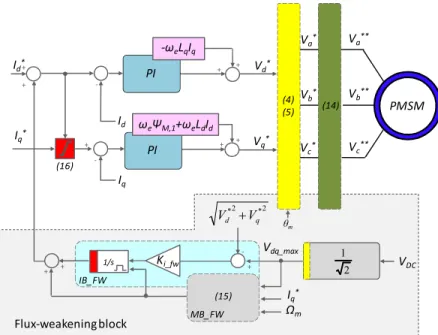
2 d I s R 2 d I d L e ω ++ + + Vd* Vq* -Id* Iq* + Id Iq PMSM Vb** Vc** Va** PI PI -ωeLqIq ωeΨM,1+ωeLdId + + Vdq_max 1/s Ki_fw -IB_FW Iq* Ωm + + MB_FW 2 * 2 * q d V V + (15) + + -VDC 2 1 Flux-weakening block Vb* Vc* Va* (14) (4) (5) (16) θm
Figure 3 Flux-weakening scheme for a three-phase wye-coupled permanent magnet synchronous machine
0 1 2 3 4 5 6 -300 -200 -100 0 100 200 300 θ e [rad] E a [ V ] E a (θe) = H1 + H3 H 1 H3
Figure 4 Phase a emf at 314.16 rad/s (1 pu) mechanical speed
0 0.5 1 1.5 2 2.5 3 -1 -0.5 0 0.5 1 Time [s] V a b c [ p u ] V a/(VDC) V b/(VDC) Vc/(VDC) 0.7 0.75 0.8 0.85 0.9 0.95 1
(a) 0 0.5 1 1.5 2 2.5 3 -1 -0.5 0 0.5 1 Time [s] I 0d q [ p u ] I 0 I0* I d Id* I q Iq* 0 0.2 0.4 0.6 0.8 1 Ω [ p u ] Ω b) 0 0.5 1 1.5 2 2.5 3 0 0.5 1 1.5 Time [s] V d q m a x [ p u ] V dq max V dq* 0 0.2 0.4 0.6 0.8 1 Ω [ p u ] Ω (c)
Figure 5 Simulation results for the three-phase wye-coupled PMSM: a) Stator reference voltages; b) 0dq frame currents; c) dq frame maximum voltage (red) and reference voltages (blue)
707 . 0 2 1 =
0 0.5 1 1.5 2 2.5 3 -4 -3 -2 -1 0 1 2 3 4 Time [s] I 0d q [ p u ] I 0 I0* I d Id* I q I q* 0 0.2 0.4 0.6 0.8 1 Ω [ p u ] Ω 0 0.25 0.5 0.75 -2 -1 0 1 2 0 0.2 0.4 0.6 0.8 1
Figure 6 Simulation results for the three-phase open-end winding PMSM using a classical control structure: 0dq frame currents
+ + + Vd* Vq* -Id* Iq* + + V0* + -+ I0* Id Iq I0 PI ωee(3θe) PI PI -ωeLqIq ωeΨM,1+ωeLdId + + Vdq_max 1/s Ki_fw -IB_FW Iq* Ωm + + MB_FW 2 * 2 * q d V V + (15) + + -RMS PMSM VbL* VcL* VaL* VbR* VcR* VaR* V0*envelope estimation Vdq max calculation V0* VDC Flux-weakening block
Zero-sequence current control loop
(4) (5) (17) θm a) START V0* ESTIMATION Vdq,max CALCULATION (21) MB_FW (15) IB_FW FLUX WEAKENING CURRENT REFERENCES b)
Figure 7 a) Flux-weakening scheme for a three-phase open-end PMSM; b) Flux-weakening algorithm 0 0.5 1 1.5 2 2.5 3 -1 -0.5 0 0.5 1 Time [s] V a b c [ p u ] V a/VDC Vb/VDC Vc/VDC 2.826 2.828 2.83 2.832 2.834 2.836 0 0.2 0.4 0.6 0.8 a) 0 0.5 1 1.5 2 2.5 3 -1 -0.5 0 0.5 1 Time [s] I 0d q [ p u ] I 0 I0* I d I d* I q Iq* 0 0.2 0.4 0.6 0.8 1 Ω [ p u ] Ω b) 0 0.5 1 1.5 2 2.5 3 -0.1 -0.05 0 0.05 0.1 Time [s] V0 [ p u ] V0 V0 envelope 0 0.2 0.4 0.6 0.8 1 Ω [ p u ] Ω c)
0 0.5 1 1.5 2 2.5 3 0 0.5 1 1.5 Time [s] Vd q m a x [ p u ] V dq max V dq* 0 0.2 0.4 0.6 0.8 1 Ω [ p u ] Ω d)
Figure 8 Simulation results for the three-phase open-end winding PMSM: a)Stator reference voltages; b) 0dq frame currents; c) V0
*
envelope detection; d) dq frame maximum voltage (red) and reference voltages (blue)
0 0.2 0.4 0.6 0.8 1 0 0.2 0.4 0.6 0.8 1 Ω [pu] T [ p u ] 0.48 0.23 Flux-weakening wye-connection Over-modulation & Flux-wekening wye-connection Flux-weakening Open-end connection ΩB= ΩB= ΩB= 0.27
Figure 9 Torque to speed diagram for wye and open-end winding connection
0 5 10 15 20 25 0.4 0.42 0.44 0.46 0.48 0.5 E h3/Eh1 Ω B [p u ] [%] Studied case
Figure 10 Third harmonic emf impact on Base Speed
(
0*,)
1.187 053 . 0 * 0 ) 21 ( max = f V VDC V = = dq V 225 . 1 2 3 =0 0.2 0.4 0.6 0.8 1 50 60 70 80 90 100 Ω [pu] V d q m a x [ % ] Eh3/Eh1 = 0% Eh3/Eh1 = 2.5% Eh3/Eh1 = 5% Eh3/Eh1 = 10% Eh3/Eh1 = 20%
Figure 11 Third harmonic emf impact on dq voltage limit
0 0.2 0.4 0.6 0.8 1 0 0.2 0.4 0.6 0.8 1 Ω [pu] T [ p u ] Eh3/Eh1 =0% Eh3/Eh1 =2.5% Eh3/Eh1 =5% Eh3/Eh1 =10% Eh3/Eh1 =20%
B
A
1
2
3
4
Figure 13 Test rig: 1) six-Leg VSI 2) Opal RT Real Time simulator 3) System monitoring and control 4) Load machine control A) three-phase Open-End Winding Machine B) Load machine
0 0.5 1 1.5 2 2.5 3 -1 -0.5 0 0.5 1 Time [s] Va b c [ p u ] V a/VDC V b/VDC V c/VDC a)
0 0.5 1 1.5 2 2.5 3 -1 -0.5 0 0.5 1 Time [s] I 0d q [ p u ] 0 0.2 0.4 0.6 0.8 1 Ω [ p u ] Ω I 0 I0* I d Id* I q Iq* b) 0 0.5 1 1.5 2 2.5 3 0 0.02 0.04 0.06 0.08 0.1 Time [s] V 0 e n v e lo p e [ p u ] 0 0.2 0.4 0.6 0.8 1 Ω [ p u ] Ω V 0 envelope c) 0 0.5 1 1.5 2 2.5 3 0 0.5 1 1.5 Time [s] V d q m a x [ p u ] 0 0.2 0.4 0.6 0.8 1 Ω [ p u ] Ω Vdq max Vdq* d)
Figure 14 Experimental results: a) 0dq reference and measured currents; b) Voltage references; c) Zero-sequence voltage reference envelope detection d) dq limit voltage reference
225 . 1 2 3 =
(
0*,)
1.166 083 . 0 * 0 ) 21 ( max = f V VDC V = = dq V 072 . 1 6 max ) 23 ( max * = = H C dq V dq V-1 -0.5 0 0.5 1 -1 -0.5 0 0.5 1 I d [pu] I q [ p u ] I dq I dq max

![Figure 7 a) Flux-weakening scheme for a three-phase open-end PMSM; b) Flux-weakening algorithm 0 0.5 1 1.5 2 2.5 3-1-0.500.51 Time [s]Vabc [pu]Va/VDCVb/VDCVc/VDC 2.826 2.828 2.83 2.832 2.834 2.83600.20.40.60.8 a) 0 0.5 1 1.5 2 2.5 3-1-0.500.51 Time [s]](https://thumb-eu.123doks.com/thumbv2/123doknet/7432493.219937/23.918.275.644.136.1071/figure-flux-weakening-scheme-weakening-algorithm-vdcvb-vdcvc.webp)