Science Arts & Métiers (SAM)
is an open access repository that collects the work of Arts et Métiers Institute of
Technology researchers and makes it freely available over the web where possible.
This is an author-deposited version published in: https://sam.ensam.eu Handle ID: .http://hdl.handle.net/10985/16736
To cite this version :
Yosbel GALAVIS ACOSTA, Lionel ROUCOULES, Lionel MARTIN - Multi-scale modelling for knowledge capitalization and Design For Manufacturability - In: Product LifeCycle Management Conference, Qatar, 2015-07 - Product LifeCycle Management Conference - 2015
Any correspondence concerning this service should be sent to the repository Administrator : [email protected]
Multi-scale modelling for knowledge capitalization and
Design For Manufacturability.
Yósbel Galavís-Acosta1, Lionel Roucoules1, Lionel Martin1 1Arts et Métiers Paris Tech, CNRS, LSIS, 2 cours des Arts et Métiers 13617
Aix-en-Provence, France
Abstract. The development of analytical technologies and simulation tools
used in the PLM increase day by day. There is a lot of data, information and knowledge associated to the product and its manufacturing plan. Precisely, during the process of design for manufacturing, the extensive number of solutions contains a lot of behaviours, associations, aspects and inputs to consider. For this reason, this paper aims at proposing a new multi-scale model as a way to provide a better structuring, better perception and better description of the many aspects involved in a product design and its manufacturing plan. The product and manufacturing plan models are based on different scale representations, characterized through “representation axes”, where the knowledge is decomposed and commit. At the same time, manufacturing knowledge is implemented to bring and evaluate the coherency among the model features.
Keywords: Design for Manufacturability (DFM), Knowledge capitalization,
Knowledge Based Engineering (KBE), Multi-scale modelling.
1 Introduction of the research context and objective
The design and industrialisation process of a product (set of parts), needs multiple models to represent each point of view of the stakeholder involved in it (design, manufacturing, assembly...). The concurrent engineering concepts aim at setting the relationships among those models in order to take into account the whole product life cycle knowledge during the design stage. Therefore, one of the main aspects treated during the product lifecycle is the relation between the design and the manufacturing [1]. In this way, “Design For Manufacturability” (DFM) emerged as an analysis methodology that provides a better relation between both aspects. This approach plays an important role in product design, and is a very useful tool to choose the best manufacturing options associated to the product design.
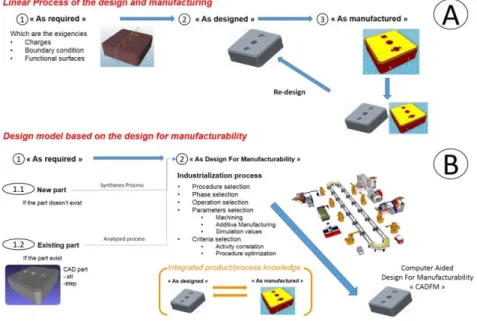
Currently, in many cases, the process of design and manufacturing is still defined linearly. That means, in the early stage of development (“as required”), the requirements associated with the product and the design features (geometric, structural, etc.) are defined. Once the requirements are validated, the product model changes to the state “as designed”, where the new characteristics are assigned (form, material, tolerance…). After this, the model goes to the stage “as manufactured” where the manufacturing process is chosen. Here, the model still requires
modifications and confrontations with the state “as required” to match (or not) the requirements (as shown in Figure 1.A). This strategy brings different limitations: generates many loopbacks and increases processing time, limits the validation of requirements, reduces the space of potential manufacturing solution and provides possible unsuited manufacturing process. Therefore, a proposal of an “as DFM” model provides greater interaction between the different states by which the product goes through [2] (as shown in Figure 1.B). This allows having an analysis more adjusted and realistic between manufacturing and design modelling. Nevertheless, this methodology needs a high amount of relations and considerations related to the design and manufacturing features.
Figure 1 Design and manufacturing strategy’s implemented in the product
development.
Taken into account the data, information and knowledge implies in the design and the manufacturing, it is mandatory to identify the relevant aspects to each stage and actor involved. For this, it is required to: formalize the information; select the important aspect related to the knowledge of the different agents (viewpoint engineers, experts in treatment, among others); and capture all this for its capitalization [3, 4]. For this reason, achieve a better understanding and integration of DFM modelling and knowledge integration, requires a strategy that interact and complete the different analysis in the best way.
Therefore, the objective to develop a representation model that integrates and manages all the knowledge, information and data, at different scales, provides an interesting methodology of study.
2 State of the arts of the fundamental principles
2.1 Design For Manufacturability
In the industry, many aspects or factors are taken into account to manufacture the product (technologies, materials, form features, tolerance…). Based on this, the “Design For Manufacturability” (DFM) rises as the response. DFM takes into account the factors and the different manufacturing processes implemented in the design phase. The main advantage of this concept is the guarantee to obtain a model of the product that can be manufactured easily. This assumption, is establish because the parameters and constraints associated with the process were planned. This improves the benefits on the treatment and the definition of design features [5]. The DFM incorporates the rules of each stage of the Product Life Cycle simultaneously and not sequentially. The design approach focuses more on the product features than on its geometry. This way the resulting geometry integrates the functional constraints and manufacturing aspects.
2.2 Knowledge Based Engineering
Usually, when the manufacturing process is followed, various agents are involved. They generate and use information, providing models (ex: CAM model) and data related to the manufacturing parameters, equipment, sequence of operations and other technical aspects required in the manufacture of the product [6, 7, 8]. This knowledge, in one way or another, should be administered properly for reuse. The “Knowledge technologies” provides an appropriate solution to these needs [3]. Due to the continuous increase of complex systems, it’s more and more difficult to access the conditions, data, information and knowledge. Based on it, the “Knowledge-based engineering” (KBE) adequately fills the requirements. The facilitation, storage and reuse of data and information are given from experts, as part of the basic related knowledge. In this sense, KBE manages to integrate systems engineering and computer-aided design in more complex design methods. Therefore the KBE responds to the continuous increase of the complex nature of the engineering process and the many inherent requirements of the different disciplines [3, 8]. The KBE facilitates the reuse of previous experiences and minimizes the need for a “from scratch” analysis in a new case study. According to its conceptual structure, KBE defines the way that different concepts interact and provide the most appropriate relationships to the environment in which they are used. [3, 17]
2.3 Multi-scale Modelling
The Multi-scale modelling usually refers to the characterization of analysis and description models of the material properties. Thence all the scales related to the material can be displayed from the atomic scale to the macro scale. To define and characterize each scale, a relation among the space and time is defined. In each one,
the most characteristic properties are evaluated. The representation is shown on the Figure 2.
Further than the one-scale modelling approach, the multi-scale modelling allows the displaying of various scales, providing a greater understanding on the modelling. This enables the integration of different aspects of the design, engineering, processing, among others, on a more solid basis. As a result, many aspects between the different scales could be connected; unifying and defining a model that fits better to the reality [10, 13, and 14]. Nevertheless, this kind of models includes a wide range of data and representations that lead to higher amount of information and more time-consuming analysis. For this, a proper definition of aspects for each scale is necessary to ensure a good analysis. In this way, just key characteristics and behaviours that represent each scale have to be integrated to reduce the need for over analysis and avoid inconsistency.
Figure 2 Composition of the working environment. [9] 2.4 Discussion of the state of the arts
The present discussion of the state of the arts is done to argue the added value of this research work with respect to:
DFM approaches. For almost 20 years DFM approach have evolved
from analysis to synthesis approaches. The first one assesses the performance indicators of the designed solutions in order to choose the “best” one (redo until right). The second is more proactive and constrains the space of design solutions with manufacturing information (right the first time). Since both situations still exist, the proposal will treat both.
Knowledge-based Engineering (KBE). Since KBE provides appropriate
relationships among concepts, we will use such approach to define design and manufacturing relations. The approach is then to couple product data (as designed) managed in CAD systems, manufacturing information (list of manufacturing techniques, machine tools, etc.) and DFM knowledge managed in a knowledge database.
Multi-scale modelling. In all DFM approach, relations (i.e. rule) between
product and manufacturing are generally applied on the macro 3D form features of the product. We argue that several rules could better fit to some other scales (meso or micro) of the product definition (ex: residual stresses generated by a manufacturing operation…). Some rules are also linked to manufacturing technologies, process plan, etc. As presented in the state of the arts, we should then model both product and manufacturing relationships at different scales and taking into account the whole manufacturing environment. This will increase the level of understanding of these relationships.
This paper focuses on the third point and gives the first specifications of the multi-scale approaches that could be used to support DFM analysis and synthesis approach.
3 Multi-scale modelling for design and manufacturing (DFM)
Taking into account the state of the art discussion, this paper proposes the establishment of a Multi-scale model related to the DFM, which provides a more detailed understanding of the manufacturing aspects involved during the product development. This integrates a more complete model visualization of the studied product and analysis of the manufacturing knowledge, information and data involved during its design. Based on it, the multi-scale modelling provides a better way to manage and understand the physical and technological considerations of each manufacturing process that have to be taken into account when a product is design.
Base on this model, a more comprehensive and effective analysis for the strategy implemented in the part design can be provided. The main idea of the proposal is based on the definition of the different scales related to the designed part and the manufacturing plan. Those scales require a well-defined set of axes. These axes establish the characteristics associated with each viewing, parameter, actor design, work environment, etc., providing the appropriate aspects or requirements to consider [11, 15, 16]. In this way, the product can be analysed in an n-dimension framework, providing detailed models and general overviews of both product and manufacturing features.
The definition of the framework, the different axes and the scales, are coming from the main aspects treated in the DFM and in the integration product/process knowledge. For the DFM, the aspects analysed in the literature and in the industrial field (as the design principles, the manufacturing capabilities, the material composition, etc. [5]) are defined over models where the progressive development (operation effectuated) and the points of view (part, machine or process) related to the product, fit to the environment in which it operate (over general consideration or over a detail complexity). Meanwhile, for the relation product/process, the interaction generated in the framework, provide the closest consideration and the existing knowledge related to the aspect of study. So far, the proposed definition of each one of this axes is based on: the granularity of observation (visualisation) of the
manufacturing phenomenon and the manufacturing environment; the knowledge to describe the consideration required during the design and manufacturing stages; the evolution of the part over the time; and the different alternatives related to each manufacturing possibilities to obtain the product.
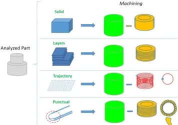
The “Visualization axe” refers to the granular representation of the knowledge and visual aspects stablished on the model. This covers the different levels of complexity linked to the product. The scale definition was based on the complexity related to the model and the possible representation that can be linked to the representation of the part. The model is divided in punctual, trajectory, layer and part where, the first one corresponds to the particular effects generated at levels tool/material interaction (ex: melting point in a FDM process or cutting point for machining), the second represents the trajectory of the tool in a 1D level (i.e. tool path), the third one a 2D mesoscopic level to link 1D trajectory to 3D features (ex: layer in FDM process, cast sections in moulding process), and the fourth one represents the general overview (3D features) of the part, as shown in the figure 3.
Figure 3 Visualization representation applied on the machining process
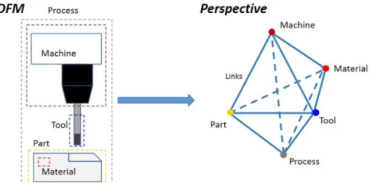
The “Perspective” axis, as shown in the figure 4, is the representation of every manufacturing feature involved in the DFM modelling (material, part, tool, machine, process). The relationships among the different features establish the geometrical, technological and physical influences on the design and manufacturing of the part. For example: the relation part/machine takes into consideration the maximum dimension of the part in a geometrical approach with respect to the working volume of the machine; the jigs and fixtures (setup) related to the features of the part and the physical solution; as well as the production capacity in the technological approach. Those relationships (i.e. knowledge) provide the limitations and characteristics regarding to the manufacturing information and the product data. The scale of the axis is related to the point of view given to the product and each of the features that compose it (material, process, machine, tool…). Even when a feature is related to
another (i.e. the material is related to the part), each one is treated separately based on the assumption that the manufacturing knowledge among the features is different.
Figure 4 DFM aspects involved in perspective representations
The “Time” represents the evolution of the part model over the time (as-required, as-DFM). Indeed, the CAD model of the part is definitely not unique over the time. In this way this axis provides an “as-required” version, where, the first stage of the process is defined and then several “as-manufacturing” versions to follow each chosen manufacturing operations, and the progression from one to another. This axis allows taking into account the part features at each visualization level over the entire manufacturing plan. For example it allows taking into account the history of residual stresses that influence the structural behaviour of the part.
The “Alternatives” representation shows the different possibilities in which, the analysed part, could have been designed and manufactured. In this way several alternatives (industrial, technological, functional, etc.) are compared in order to obtain the best options according to the needs or limitations of the product and the industrial performances.
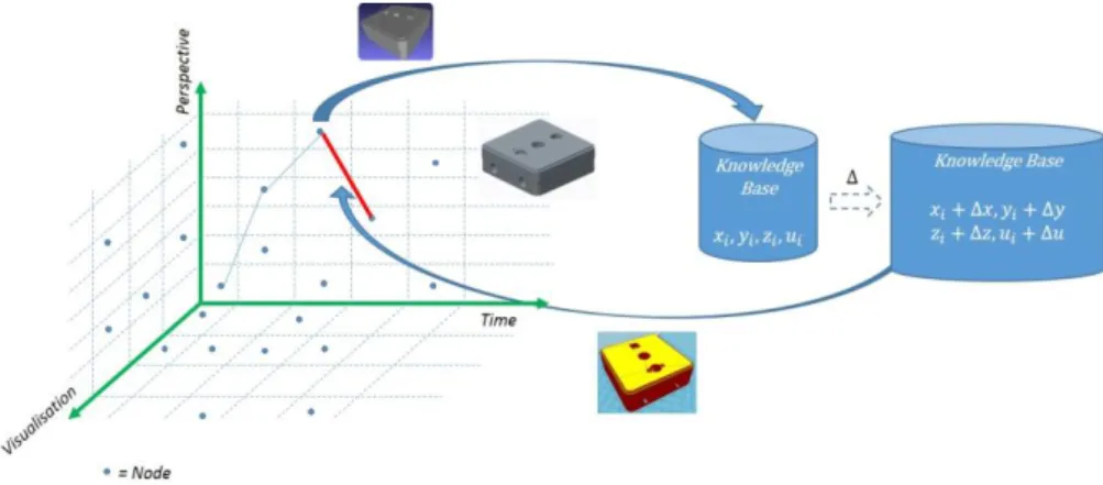
As shown on figure 5, the interaction among those four axes defines the path taken to model the study part, establishing the manufacturing knowledge involved at each stage. Each interaction (denominated as node), in the modelled spaces, refers to one DFM model. According to the 4 axes space, each node Ni can then be noted Ni (xi, yi,
zi, ui). The knowledge stored, in the knowledge base, then refers to the relationships
among xi, yi, zi and ui or dxi, dyi, dzi and dui. In the first case the knowledge insure the
intrinsic DFM coherency of the node, in the second case the extrinsic DFM coherency among serval nodes. Based on this modality, a structured knowledge path could be generated and modelled from the design to the manufacturing. It also, allows discover the possible complications along the related path. In this way the problems and the unsuccessful procedures will be avoided; minimizing the analysis time and maximizing the precision of the expected results. Moreover, it allows capturing the decision making taken during the modelling activities. Each decision is therefore a link among: the data represented in the model; the information provided by the information base; and the knowledge modelled in the knowledge base. Based upon the data, information and knowledge corresponding to each node, this DFM approach can be used in both analysis and synthesis ways (cf. 2.4). The possible methodology
to achieve the DFM solution is presented, as well the alternative models. It also could be compared and propagated to the different scales in order to obtain a homogenization and integration among them.
Figure 5 Knowledge representation of the fabrication analysis of a product
The multi-scale approach provides a complete and detailed analysis of the knowledge, information and data, regarding to the factors and guidelines imposed during the analysis. The agent can perform the required study based on them; obtaining a better result or providing a newly acquired conception strategy. That provides the considerations and characteristics to represent the geometrical model; leading to obtain a part according to the effects and limitations of the manufacturing process in the design. It is important to notice that the multi-scale modelling composition applied onto the design and manufacturing will be able to clarify the result and choose the best approach. But, it also need that the agents involved, provide the require information whenever it is required.
4 Multi-scale representation applied on a manufacturing case
study
To visualize the methodology implemented in the multi-scale modelling, an example is realized to describe the knowledge path follow. With this, the user (in this case, the designer) can see the evolution (from the requirement till the last operation) of the design related to the perspective selected, considering the degree of complexity interested. The implementation of the framework allows to precise the positioning of the requirements. The example is based on the condition: “The designer requires seeing the design aspects related to the drilling of a through hole in a turning machine”. Based on this, the first nodes related to the need are:
Node 1 (N1): Time: As required; Visualization: Solid; Perspective: Process
(drill, through hole)
Node 2 (N2): Time: As required; Visualization: Solid; Perspective: Machine
Each node definition relies on specific modelling features, and takes into consideration the requirement “as-required”. The difference between the two alternative paths corresponds to the knowledge evaluated. For the first path, the second node is based on the “process” (i.e. manufacturing operation), defining this way, the best consideration regarding to the drilling process. Meanwhile, in the second path, the relation is related to the “machine”, responding to the requirements, capacities and capabilities of this according to the perspective evaluated. Next, the “part”, the “tool” and the “material” data are given, providing the modelling alternatives. As the previous phase, the selected feature will define the progression over the result. As result, the designed path for the case studied and the correspondent model will be based on the N1, N3, N7, N8 nodes. To compare the different alternatives, in the figure 7 are shown the paths selected for the case studied regarding to the initial condition taken. Where, can be seen the different consideration regarding to the path followed, establishing the knowledge to use in the modelling.
Figure 7 Interaction between the different axes for the study case
5 Conclusion and future perspectives
The Multi-scale representation constitutes a promising methodology to allow analysis of complex knowledge, information and data in order to manage them. At the same time, it provides a visualization of the different aspects involved in the design and the manufacturing environment. This approach avoids possible information and data overlapping and overload, concerning to the physical characteristics and the relevant aspects related to the product. Then, the most representative views or the most important relationship are defined so that the product fits better to what is needed. The future perspectives focus on the implementation of the model for the knowledge capitalization and reusing; then, the dynamic implementation of the model (active interaction between the model and the knowledge base capitalized). This way,
the knowledge base and the multi-scale model will be implemented simultaneously, providing progressively the requirements and limitations all along the design phase.
6 References
[1] Umeda Y., Takata S., et al. “Toward integrated product and process life cycle
planning—An environmental perspective” CIRP Annals - Manufacturing
Technology vol. 61 (2012) p.p. 681–702
[2] Boothroyd G. “Design for X: Design for Manufacture and Assembly: The Boothroyd-Dewhurst Experience” Marcel Dekker, Inc., NY – USA 2002 [3] Milton N. R. “Knowledge Technologies” 3rd Edition, Editorial Polimetrica,
Monza (Milan) – Italy, 2008.
[4] Al-Ashaab A., Molyneaux M., Doultsinou, A., Brunner B., Martínez E. “Knowledge-based environment to support product design validation” Knowledge-Based Systems, vol. 26 (2012) p.p. 48–60
[5] Bralia J. G. “Design For Manufacturability Handbook” Ed. McGraw-Hill, 1998. [6] Monticolo D., Mihaita S., Darwich H., Hilaire V., “An agent-based system to
build project memories during engineering projects” Knowledge-Based Systems, vol. 68 (2014) p.p. 88–102
[7] Sánchez-Pi N., Carbó J., Molina J. M. “A knowledge-based system approach for a context-aware system” Knowledge-Based Systems, vol. 27 (2012) p.p. 1–17 [8] Liu D-R, Lin C-W, “Modeling the knowledge-flow view for collaborative
knowledge support” Knowledge-Based Systems vol. 31 (2012) p.p. 41–54. [9] Pareige P. “Irradiation effects in structural components of nuclear reactor: an
experimental nanoscale point of view” Colloque National MECAMAT - Aussois 2013 dans http://mecamat2013.lmgc.univ-montp2.fr/presentations.htm.
[10] Weinan E. “Principles of Multiscale Modeling”, (2011) p.p. 1-17
[11] Laukkanen A., Holmberg K. , Wallin K., “Multiscale modelling of engineering materials”, Multiscale modelling and design for engineering application at VTT (2013) Finland p.p. 10-18.
[12] Hoque A.S.M., Halder P.K., Parvez M.S., Szecsi T., “Integrated manufacturing features and Design-for-manufacture guidelines for reducing product cost under CAD/CAM environment” Computers & Industrial Engineering 66 (2013) 988– 1003
[13] Elliot J.A., “Introduction to Multiscale Modelling of Materials”, Multiscale Modelling Methods for Applications in Materials Science vol 19, p.p. 1-20 [14] Liu W.K., Qian D., Gonella S., Li S., Chen W., Chirputkar S., “Multiscale
methods for mechanical science of complex materials: Bridging from quantum to stochastic multiresolution continuum” International journal for numerical methods in engineering.
[15] Horstemeyer M., “Multiscale Modeling: A Review” Practical Aspects of Computational Chemistry, ed. J. Leszczynski and M.K. Shukla, Springer Science+Business Media, pp. 87-135, 2009.
[16] Revuelta A.,“Vertical multiscale modelling” Multiscale modelling and design for engineering application at VTT (2013) Finland p.p. 10-18.
[17] Kendall S.L., Creen M., “An Introduction to Knowledge Engineering”, Springer-Verlag, London 2007.
![Figure 2 Composition of the working environment. [9]](https://thumb-eu.123doks.com/thumbv2/123doknet/7370647.214651/5.892.269.629.476.693/figure-composition-working-environment.webp)