Science Arts & Métiers (SAM)
is an open access repository that collects the work of Arts et Métiers Institute of Technology researchers and makes it freely available over the web where possible.
This is an author-deposited version published in: https://sam.ensam.eu
Handle ID: .http://hdl.handle.net/10985/15937
To cite this version :
Taoufik QORIA, Thibault PREVOST, Guillaume DENIS, François GRUSON, Frédéric COLAS, Xavier GUILLAUD - Power Converters Classification and Characterization in Power Transmission Systems - In: EPE'19 ICCE EUROPE, Italie, 2019-09-02 - n/a - 2019
Any correspondence concerning this service should be sent to the repository Administrator : [email protected]
Power Converters Classification and Characterization
in Power Transmission Systems
T. QORIA*, T. PREVOST†, G. DENIS†, F. GRUSON*, F. COLAS*, X. GUILLAUD*
*Univ. Lille, Arts et Metiers ParisTech, Centrale Lille, HEI, EA 2697-L2EP-Laboratoire d’Electrotechnique et
d’Electronique de Puissance, F-59000 Lille, France
†Réseau de Transport d’Electricité, Versailles, France
E-Mail: [email protected]
Acknowledgements
This project has received funding from the European Union’s Horizon 2020 research and innovation program under grant agreement No 691800. This paper reflects only the author’s views and the European Commission is not responsible for any use that may be made of the information it contains.
Keywords
«Power transmission grids», «Power converters control», «Power converters classification», «Power converters transient behavior»,
Abstract
Because of the throng of control strategies based Voltage Source Converters (VSC) recently proposed in the literature; their classification and characterization are becoming a trending topic. The high similarities of the proposed control strategies may lead to confusions and a misunderstanding of vocabulary. Therefore, this paper seeks first to highlight the possible features fulfilled by power converters in a large power system. The combination of these features is used to classify power converters. Furthermore, power converters can be seen by a power transmission system operators as black boxes, and they may have the same inputs and outputs, which makes their characterizations more difficult. This paper looks to show that only the fundamental nature of the source has an influence on the system dynamic behavior, thus, power converter can be characterized from their transient behavior in response to grid disturbances.
Introduction
In the near future, renewable energy sources (RESs), such as wind and solar photovoltaic (PV) systems, will be a major contributor in the power system, their integration is essentially motivated by environmental reasons first and also their cost reduction during last years; as a consequence, a large-scale deployments are happening around the world. Some countries such as Germany, Ireland and Denmark have already achieved a high penetration of renewable energy sources. However, considering the power system stability criterion, the penetration rate of RESs must be monitored in order to keep the same level of reliability as in the conventional power system (e.g.; Ireland limits its instantaneous penetration to 55% [1]).
Renewable energy sources are interfaced to the power system through power electronic devices (e.g.; voltage source converters). These latter are fully dependent on the control law to manage the electrical power follow. Today, the power system stability and services (i.e.; voltage regulation and frequency regulation…) are mainly ensured by synchronous machines, while, power converters are only injecting active and reactive power relaying on the grid information. In research area, recent projects have been
launched that aim to achieve a power system with 100% power electronics penetration[2]–[4], where,
better dynamic performances. AC grid without dedicated synchronous generators has been widely discussed in micro-grid [5] and Uninterruptible Power Supply [6] and it starts to be extended to large grid such as power transmission system [7], [8]. In this context, many developments have been made and especially in terms of control strategies [9]–[16]. The increase of different controls in the literature makes power converters classification and characterization as a trending topic. In the literature, power converters control laws are generally classified as grid-forming (GF), grid-feeding/grid-following (Gf) or grid-supporting controls. Grid-forming and grid-feeding are the cases [17] where power converters behave as voltage and current sources respectively, while the grid-supporting classification remains generic and does not allow to classify precisely the contributions of power converters from their system level, since, it is an extension of both grid-forming or grid-feeding controls with the same system inputs and outputs.
Authors in [5] suggest that each control law should be divided into non-interactive and grid-interactive strategies where the grid-feeding and grid-forming are defined as a non-grid-interactive controls while the grid-supporting control is defined as an interactive control since it uses the grid information with or without communication to provide services. To avoid confusions about grid-supporting controls, authors in [17], [18] divide the grid-supporting converter into GSGf (i.e.; grid-supporting grid-feeding) and GSGF (i.e.; grid-supporting grid-forming). In [19], authors propose a subdivision of the grid-supporting grid-forming in AC voltage forming, frequency forming or grid-forming. These classifications are relative and consider only the contribution of power converters to the AC grid, moreover, with the increase of the proposed control strategies that some of them do not belong to any category, the vocabulary will no longer be easy to understand.
Power converters could be distinguished by two principle levels:
Low level control: It characterizes the nature of the power source (i.e.; current controlled VSC or AC voltage controlled VSC).
High level control: It ensures the synchronization of power converters and provides different types of services to the AC grid.
Given this distinction:
- The classification of power converters is done by a combination of the low level control functionalities and the high level control functionalities.
- It is important to highlight that in the first instant after an event, only the fundamental nature of the source has an influence on the system dynamic behavior. Indeed, the high level control is always slower than the low level control.
Power converter control structures and their classification
Figure 1 shows a voltage source converter with a DC power source, its control architecture, and interconnection to a power system through its terminals [3].
Fig. 1. Local control architecture
The voltage source converter and its device-level control are shown in the upper left corner. The inner control aims to regulate the instantaneous AC voltage, the converter output current or both of them.
This control loop typically consists of one or two cascaded controllers. From a power system point of view, the voltage source converter can be seen as an AC voltage source which can be driven by the control law. It exchanges active and reactive power with the main grid through its point of common coupling (PCC) at the system level. The interaction with the main grid is ensured by the outer control loop. It allows power converter to synchronize, energize and/or to provide services to the main grid. In this section, a variety of control strategies are presented and discussed in order to highlight the main differences and similarities between them.
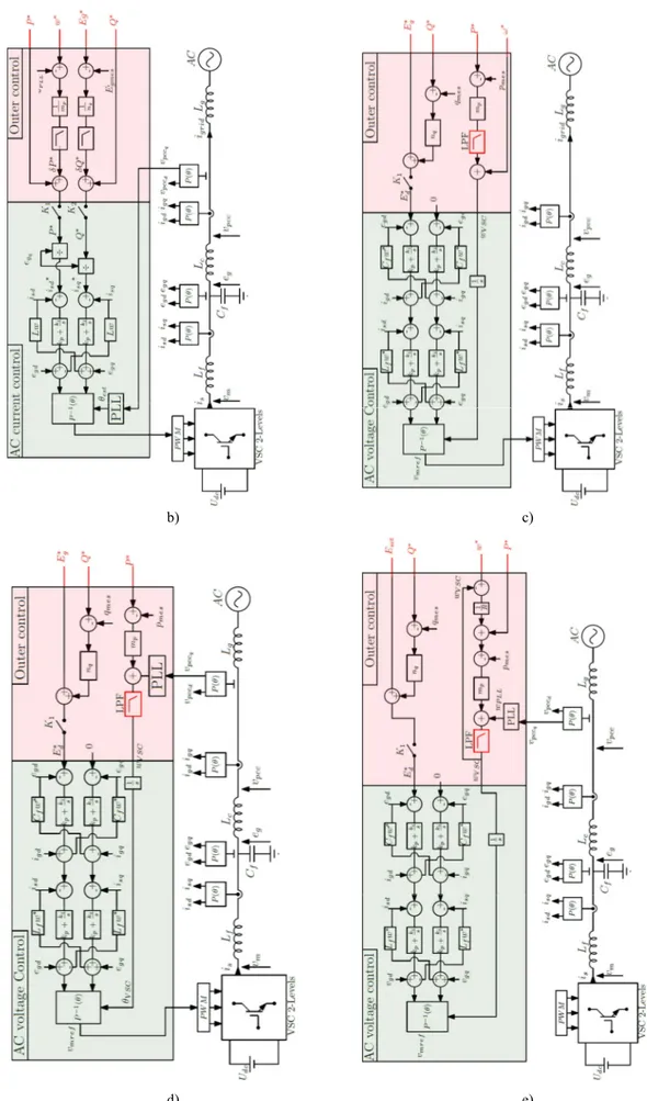
Fig. 2 illustrates five control strategies that summarize the controls used in the literature, they could be based on droop control [9], [20], virtual synchronous machine [12], virtual synchronous generator [14], matching control [10] and virtual oscillator [16]. These concepts perform the same tasks and they are mathematically the same [9], [21], [22], therefore only droop control is used in this paper.
- Strategy “A” [23]: It consists of two PI controllers for current regulation. Based on this control strategy, power converters behave as current sources and aim to exchange active and reactive currents specified by the references 𝑖∗ . Power converters based “Strategy A” can operate only in a grid-connected mode and require grid information to be synchronized.
- Strategy “B” [17]: It is an extension of “Strategy A”. Power converters operate as current
sources and aim to support AC voltage (K = 1 (breaker is closed) and
K = 0 (breaker is closed)) by adjusting the reactive power Q∗ reference, supporting the frequency by adjusting the active power P∗ reference or supporting both of them (K = 1 and K = 1). Similarly to “Strategy A”, “Strategy B” is used to operate only in a grid-connected mode and need grid information to be synchronized.
- Strategy “C” [7], [9], [10], [17], [24], [25]: Based on this control strategy, power converters operate as voltage sources. This control strategy allows power converters to support AC voltage by adjusting the reactive droop setpoint Q∗, and proving inertia effect by adjusting the low pass-filter (LPF) cut-off frequency [9], [26]. This control strategy allows power converters to be synchronized to the main grid through the outer loop “power droop control in this case”. Contrary to “Strategy A” and “Strategy B”, “Strategy C” operates whatever the grid-topology. This control strategy allows power converters to form an AC grid while respecting the present specifications of power transmission systems.
- Strategy “D”: This control strategy is very similar to “Strategy C”, while, by changing the frequency 𝜔∗ by the grid frequency estimation; this control strategy does not allow power converters to support the grid-frequency, but injecting the active power specified by 𝑃∗ and providing inertial effect by modifying the low-pass filter (LPF) cut-off frequency. This control strategy operates only in grid-connected mode.
- Strategy “E”: This control strategy is very similar to the virtual synchronous machine concept [27]. The additional frequency control loop allows power converters to achieve the same functionalities as “Strategy C” with more flexibility and degrees of freedom. Power converters based “Strategy E” operate whatever the grid configurations; and they are able to form an AC grid while respecting the present specifications of power transmission system.
b) c)
d) e)
Fig. 2. Power converters control strategies. a) Strategy “A”, b) Strategy “B”, c) Strategy “C”, d) Strategy “D”, e) Strategy “E”.
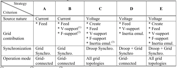
From the previous description of each control strategy, in power transmission system based 100% power electronics, the AC grid should contain at least one of the control strategies “Strategy C” or “Strategy E” in order to form the AC system while ensuring the present power system specifications. Table I summarize the main differences between these strategies:
Table I. Differences between control strategies Strategy
Criterion A B C D E
Source nature Current Current Voltage Voltage Voltage
Grid contribution * Feed * Feed * V-support(1) * F-support(2) * Create * Feed * V-support * F-support * Inertia emul.(3) * Feed * V-support * Inertia emul. * Create * Feed * V-support * F-support * Inertia emul. Synchronization Grid Synchro. Grid Synchro.
Droop Synchro. Droop + Grid Synchro
Droop + Grid Synchro. Operation mode
Grid-connected Grid-connected All grid topologies Grid-connected All grid topologies (1)
AC voltage supporting. (2) Frequency supporting. (3) Emulation of the inertia effect.
From Table I, it is possible to notice that power converters could feed the grid, support the grid, creating the grid, or ensuring all this functionalities at the same time while being a voltage source or a current source or being synchronized through local measurements or using the grid information. Therefore, taken only one criterion to classify power converters seem to be very complex to understand e.g.; in the literature, authors in [17] define “Strategy B”, “Strategy C” and “Strategy E” as grid-supporting concepts, however, from one side, the “grid-supporting” concept cannot precisely define the contribution of the power converter to the main grid, from another side, they have a different source nature, different way to synchronize and different operation mode. Consequently, the classification of power converters can be done by a combination of all the functionalities listed in the Table I.
Power converters characterization based on their dynamic behavior
In large power transmission systems, operators do not have access to the information about the control used for power converters, but they have access only to the system inputs and outputs (I/O), these latter can give some ideas about some functionalities that power converters can fulfill, while, they cannot define precisely the nature of power sources. Hence, the question is how power transmission system operators can characterize power sources nature? The answer lies on their transient behavior, since, current sources and voltage sources have different dynamic behavior in response to the grid disturbances.
Physically, voltage sources provide power naturally following a grid disturbances in order to ensure power balance (i.e.; fast transient response), while, current sources react to these disturbances following the control dynamics (i.e.; slow transient response). These properties are the main keys to distinguish the nature of the power converters without any knowledge of the control law used.
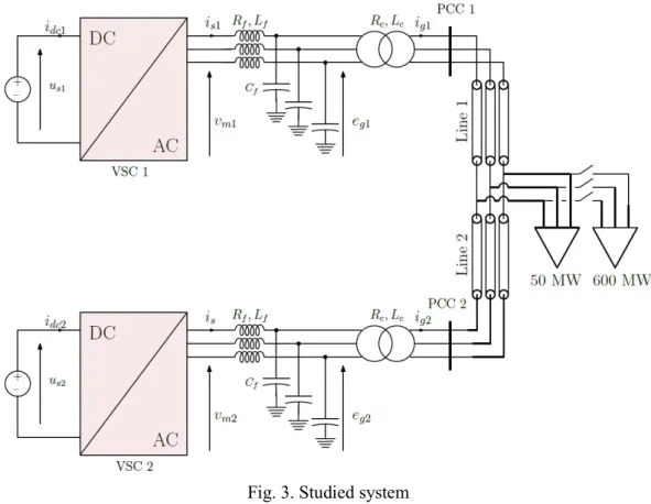
To illustrate the behavior of power converters in response to the grid disturbances, the grid case in Figure 3 is performed in MATLAB/Simulink. The grid case comprises of two power converters connected to a load through two lines. The load is assumed to be a pure resistance. The strategy “A” is out of this study, since it can be easily characterized power converters from their inputs and outputs. The results of the test cases are focused on the active power; the reactive and voltage droop control are neglected in this paper. Eight test cases are studied to illustrate the different transient behaviors depending on the grid topology and the control used:
1- Converter 1 and converter 2 are based on the control strategy “Strategy C”; the same length for the lines (100km).
2- Converter 1 and converter 2 are based on the control in “Strategy C”; line 1 length is 100km is and the line 2 length is 10km.
3- Converter 1 is based on the control strategy in “Strategy C”; Converter 2 is based on the control strategy “Strategy E”; the same length for the lines (100km).
4- Converter 1 is based on the control strategy in “Strategy C”; Converter 2 is based on the control strategy “Strategy E”; line 1 length is 100km and the line 2 length is 10km.
5- Converter 1 is based on the control strategy in “Strategy D”; Converter 2 is based on the control strategy “Strategy C”; the same length for the lines (100km).
6- Converter 1 is based on the control strategy in “Strategy D”; Converter 2 is based on the control strategy “Strategy C”; line 1 length is 100km and the line 2 length is 10km.
7- Converter 1 is based on the control strategy in “Strategy C”; Converter 2 is based on the control strategy “Strategy B”; the same length for the lines (100km).
8- Converter 1 is based on the control strategy in “Strategy C”; Converter 2 is based on the control strategy “Strategy B”; line 1 length is 100km and the line 2 length is 10km.
Fig. 3. Studied system System parameters are listed in the following Table.
Table II. System parameters
𝑃 1 𝐺𝑊 𝑅 0.005 p.u 𝑐𝑜𝑠𝜙 0.95 𝐿 0.15 p.u 𝑓 50 𝐻𝑧 𝑅 0.005 p.u 𝑈 640 𝑘𝑉 𝑋 0.3 Ω/𝑘𝑚 𝑈 320 𝑘𝑉 𝑅 0.03 Ω/𝑘𝑚 𝐶 0.066 p.u 𝐶 10 μF 𝐿 0.15 p.u
As show in Figure 4, the analysis shows the steady state but also a zoom on the first 5ms following the load change.
a) b)
c) d)
e) f)
g) h)
Fig.4. Transient behavior of power converters following a load change. a) Test case 1, b) Test case 2, c) Test case 3, d) Test case 4, e) Test case 5, f) Test case 6, g) Test case 7, h) Test case 8
Following a load change, it can be clearly noticed from Figure 4.a, 4.c and 4.e that power converters have the same transient behavior during the first 5ms in spite of the difference between their outer controls. During this period, power converters react naturally to the power demand according to their output impedances. In this case, both converters are at the same distance of the load, the provided active power is equally distributed between them in the first instants. In the case where the distance between power converters and the load is not the same, the converter electrically close to the load provides more power, this phenomenon is well illustrated in Figure 4.b, 4.d and 4.f. The behavior noticed from these test cases confirms that power converters behave as voltage sources. The comparison between Figure 4a and 4c highlights the importance of the outer loop after the first milliseconds. Indeed, since the functionalities fulfilled by these control strategies can be considered as the same after several second, the way to achieve this task is different. This explains the different behaviors in the first 100ms.
Conversely, strategies "C" and "D" do not fulfill the same functionalities since strategy "C" brings a primary frequency support which is not the case of Strategy "D". However, due to their voltage source nature, their behavior is the same in the first 5ms.
In Figure 4.g and 4.h, the transient behavior of power converters is fundamentally different regardless the length of lines towards the load i.e.; power converter 2 takes all the load despite being farther from the load than the converter 1, which confirms that power converter 2 behaves as a voltage source, and power converter 1 behaves as a current source.
Conclusion
This paper presents a topic on the classification and characterization of power converters. The main conclusions drawn from this paper are:
- The classification of power converters can be done by a combination of the functionalities fulfilled by the low level control and the high level control.
- Whatever the functionalities fulfilled by power converters and their (I/Os) similarities, their transient behavior could be different depending on their source nature,
- In this paper a focused on the first 5ms has been make. After 5ms, outer controls start to react in order to fulfil the functionalities of power converters. The recovering dynamics and the steady state of all power converters depend mainly on the controller parameters i.e.; droop gain, power controllers, low-pass filter gains …
References
[1] B. Kroposki et al., “Achieving a 100% Renewable Grid: Operating Electric Power Systems with Extremely High Levels of Variable Renewable Energy,” IEEE Power Energy Mag., vol. 15, no. 2, pp. 61– 73, Mar. 2017.
[2] “H2020 Migrate.” [Online]. Available: https://www.h2020-migrate.eu/. [Accessed: 09-Sep-2018]. [3] “WP3 - Control and Operation of a Grid with 100% Converter-Based Devices.”
https://www.h2020-migrate.eu/.
[4] “https://www.promotion-offshore.net/.” .
[5] F. Katiraei, R. Iravani, N. Hatziargyriou, and A. Dimeas, “Microgrids management,” IEEE Power Energy Mag., vol. 6, no. 3, pp. 54–65, May 2008.
[6] J. M. Guerrero, J. C. Vasquez, J. Matas, M. Castilla, and L. G. de Vicuna, “Control Strategy for Flexible Microgrid Based on Parallel Line-Interactive UPS Systems,” IEEE Trans. Ind. Electron., vol. 56, no. 3, pp. 726–736, Mar. 2009.
[7] G. Denis, “Les nouvelles stratégies de contrôle d’onduleurs pour un système électrique 100% interfacé par électronique de puissance,” thesis, Ecole centrale de Lille, 2017.
[8] Q. Cossart, F. Colas, and X. Kestelyn, “Simplified converters models for the analysis and simulation of large transmission systems Using 100% power electronics,” in 2018 20th European Conference on Power Electronics and Applications (EPE’18 ECCE Europe), 2018, p. P.1-P.10.
[9] T. Qoria, F. Gruson, F. Colas, G. Denis, T. Prevost, and X. Guillaud, “Inertia effect and load sharing capability of grid forming converters connected to a transmission grid,” in 15th IET International Conference on AC and DC Power Transmission (ACDC 2019), 2019, pp. 1–6.
[10] C. Arghir, T. Jouini, and F. Dörfler, “Grid-forming control for power converters based on matching of synchronous machines,” Automatica, vol. 95, pp. 273–282, Sep. 2018.
[11] R. Hesse, D. Turschner, and H.-P. Beck, “Micro grid stabilization using the virtual synchronous machine (VISMA),” Renew. Energy Power Qual. J., vol. 1, no. 07, pp. 676–681, Apr. 2009.
[12] H. Beck and R. Hesse, “Virtual synchronous machine,” in 2007 9th International Conference on Electrical Power Quality and Utilisation, 2007, pp. 1–6.
[13] Q. Zhong and G. Weiss, “Synchronverters: Inverters That Mimic Synchronous Generators,” IEEE Trans. Ind. Electron., vol. 58, no. 4, pp. 1259–1267, Apr. 2011.
[14] J. Driesen and K. Visscher, “Virtual synchronous generators,” in 2008 IEEE Power and Energy Society General Meeting - Conversion and Delivery of Electrical Energy in the 21st Century, 2008, pp. 1–3. [15] M. Ashabani, F. D. Freijedo, S. Golestan, and J. M. Guerrero, “Inducverters: PLL-Less Converters With
Auto-Synchronization and Emulated Inertia Capability,” IEEE Trans. Smart Grid, vol. 7, no. 3, pp. 1660– 1674, May 2016.
[16] B. B. Johnson, S. V. Dhople, A. O. Hamadeh, and P. T. Krein, “Synchronization of Parallel Single-Phase Inverters With Virtual Oscillator Control,” IEEE Trans. Power Electron., vol. 29, no. 11, pp. 6124–6138, Nov. 2014.
[17] J. Rocabert, A. Luna, F. Blaabjerg, and P. Rodríguez, “Control of Power Converters in AC Microgrids,” IEEE Trans. Power Electron., vol. 27, no. 11, pp. 4734–4749, Nov. 2012.
[18] A. D. Paquette, M. J. Reno, R. G. Harley, and D. M. Divan, “Sharing Transient Loads : Causes of Unequal Transient Load Sharing in Islanded Microgrid Operation,” IEEE Ind. Appl. Mag., vol. 20, no. 2, pp. 23– 34, Mar. 2014.
[19] U. Markovic, O. Stanojev, P. Aristidou, and G. Hug, “Partial Grid Forming Concept for 100% Inverter-Based Transmission Systems,” p. 6.
[20] T. Qoria, F. Gruson, F. Colas, X. Guillaud, M. Debry, and T. Prevost, “Tuning of Cascaded Controllers for Robust Grid-Forming Voltage Source Converter,” in 2018 Power Systems Computation Conference (PSCC), 2018, pp. 1–7.
[21] J. Liu, Y. Miura, and T. Ise, “Comparison of Dynamic Characteristics Between Virtual Synchronous Generator and Droop Control in Inverter-Based Distributed Generators,” IEEE Trans. Power Electron., vol. 31, no. 5, pp. 3600–3611, May 2016.
[22] T. Jouini, U. Markovic, and D. Groß, “Deliverable 3.3: New options for existing system services and needs for new system services,” p. 105.
[23] F. Blaabjerg, R. Teodorescu, M. Liserre, and A. V. Timbus, “Overview of Control and Grid Synchronization for Distributed Power Generation Systems,” IEEE Trans. Ind. Electron., vol. 53, no. 5, pp. 1398–1409, Oct. 2006.
[24] S. D’Arco, J. A. Suul, and O. B. Fosso, “Automatic Tuning of Cascaded Controllers for Power Converters Using Eigenvalue Parametric Sensitivities,” IEEE Trans. Ind. Appl., vol. 51, no. 2, pp. 1743–1753, Mar. 2015.
[25] D. Groß, M. Colombino, J.-S. Brouillon, and F. Dörfler, “The effect of transmission-line dynamics on grid-forming dispatchable virtual oscillator control,” ArXiv180208881 Math, Feb. 2018.
[26] S. D’Arco and J. A. Suul, “Equivalence of Virtual Synchronous Machines and Frequency-Droops for Converter-Based MicroGrids,” IEEE Trans. Smart Grid, vol. 5, no. 1, pp. 394–395, Jan. 2014.
[27] S. D’Arco, J. A. Suul, and O. B. Fosso, “A Virtual Synchronous Machine implementation for distributed control of power converters in SmartGrids,” Electr. Power Syst. Res., vol. 122, pp. 180–197, May 2015.
![Figure 1 shows a voltage source converter with a DC power source, its control architecture, and interconnection to a power system through its terminals [3]](https://thumb-eu.123doks.com/thumbv2/123doknet/7441047.220652/3.892.155.735.811.1090/figure-voltage-source-converter-control-architecture-interconnection-terminals.webp)
![Fig. 2 illustrates five control strategies that summarize the controls used in the literature, they could be based on droop control [9], [20], virtual synchronous machine [12], virtual synchronous generator [14], matching control [10] and vir](https://thumb-eu.123doks.com/thumbv2/123doknet/7441047.220652/4.892.239.656.887.1144/illustrates-strategies-summarize-controls-literature-synchronous-synchronous-generator.webp)