UNIVERSITÉ DE MONTRÉAL
MULTIDISCIPLINARY DESIGN OPTIMIZATION (MDO) OF TRANSONIC
FAN BLADE
SAIMA NAZ
DÉPARTEMENT DE GÉNIE MÉCANIQUE ÉCOLE POLYTECHNIQUE DE MONTRÉAL
THÈSE PRÉSENTÉE EN VUE DE L’OBTENTION DU DIPLÔME DE PHILOSOPHIAE DOCTOR
(GÉNIE MÉCANIQUE) DÉCEMBRE 2014
UNIVERSITÉ DE MONTRÉAL
ÉCOLE POLYTECHNIQUE DE MONTRÉAL
Cette thèse intitulée :
MULTIDISCIPLINARY DESIGN OPTIMIZATION (MDO) OF TRANSONIC FAN BLADE
présentée par : NAZ Saima
en vue de l’obtention du diplôme de : Philosophiæ Doctor a été dûment accepté par le jury d’examen constitué de :
M. LAURENDEAU Éric, Ph. D., président
M. TRÉPANIER Jean-Yves, Ph. D., membre et directeur de recherche M. TRIBES Christophe, Ph. D., membre et codirecteur de recherche M. GUIBAULT François, Ph. D., membre
DEDICATION
ACKNOWLEDGEMENTS
First of all, I would like to express my deep gratitude to my supervisor, Professor Dr. Jean-Yves Trepanier, for offering me this opportunity, providing guidance, encouragement, precious advices and sharing his expertise throughout this research project. I would like to thank him for his entire invaluable moral, ethical and off course technical training.
I would like to special thanks to my co-supervisor Dr. Christophe Tribes (Research Associate), whose continuous guidance and excellent support from the initial to the final level of the project supported me to develop an understanding of the subject.
I am thankful to Mr. Eddy Petro (Research Associate) for his help related to softwares and share his valuable expertise during the completion of the project.
I would like to thank to the Pratt & Whitney Canada, NRC and Bombardier Aerospace, not only for providing the project financial support, but also for providing an opportunity to work in such an innovative project. I deeply appreciate the help from François Brophy at Pratt & Whitney to give instructive comments during this research work. I also benefited from discussion with Peter Townsend & Hong Yu at Pratt & Whitney Canada. In particular, I would like to special thanks to Mr. Jason Nichols (Aerodynamic Engineer) from Pratt & Whitney Canada for his valuable comments and suggestions.
Furthermore, I greatly appreciate the direct and indirect help of Mechanical engineering departmental staff, and specially Technical Support of IT group.
I would like to thank all to my colleagues Alexandre Lupien, Maryam Khelghatibana, Martin Gariépy, Sébastien Leclaire, Martin Weil Brenner, Foad Mehdi Zadeh, Benoit Malouin, Sami Ammar, Radouan Boukharfane, and many others intern students in the IDEA chair lab who supported me in any respect during the completion of the project and for the many informative discussions that I had with them.
Finally, I would like to special thanks to my family for their encouragement and continued support to study abroad, specially my sister Aasma who has been my greatest supporter during my PhD and stay in Montréal.
RÉSUMÉ
La conception de pales d’un rotor est une tâche complexe et difficile en raison de l’écoulement transsonique, du large espace de design et de l’implication de plusieurs disciplines de l'ingénierie dans le but d’augmenter les performances de métriques multidisciplinaire tels que l'efficacité, le rapport de pression, le stress. Pour faire face à tous ces défis, une comparaison d’approches pour les optimisations aérodynamiques et multidisciplinaires automatisés (MDO) des pales de soufflante transsonique est présentée. Le processus de conception proposé intègre une méthode de paramétrisation géométrique des pales, une modélisation CAO et des outils d’analyse haute-fidélité pour l'aérodynamique, la structure et la dynamique. Une méthode de paramétrisation de pales à multi-niveau a été utilisée pour modifier efficacement la géométrie de la pale avec un faible nombre de variables de conception. Le modèle CAO a été construit dans CATIA afin d'utiliser un modèle commun pour les analyses de structure et dynamiques. Le modèle des équations de Navier-Stokes (RANS) tridimensionnelles moyennées intégré au logiciel commercial CFD ANSYS CFX, a été utilisé pour l'analyse aérodynamique du rotor transsonique tandis qu’un modèle éléments finis (EF) implémenté sur ANSYS a été utilisé pour réaliser les analyses de structure et dynamique. Des algorithmes d'optimisation heuristiques et hybrides sont utilisés pour résoudre le problème d'optimisation de la forme des pales. La vérification des codes et des méthodes a été effectuée en comparant les résultats calculés à des données expérimentales disponibles dans la littérature pour le NASA Rotor 67, un cas test représentatif d'écoulement complexes en trois dimensions.
Afin de vérifier la faisabilité du processus automatisé intégré dans l'optimisation, une optimisation aérodynamique visant à maximiser l'efficacité du point de conception tout en maintenant le débit massique et le rapport de pression constant, est élaboré et exécuté pour redessiner le cas de test Rotor 67. En outre, ce cas a aidé à sélectionner l'algorithme d'optimisation adapté à la résolution du problème et explorer l'espace de conception. Cependant, la conception de pale de soufflante transsonique est inévitablement un processus pluridisciplinaire qui nécessite la participation de nombreuses disciplines telles que l'aérodynamique, la structure, la dynamique, etc., au cours des différentes étapes du processus de conception. En outre, les procédures de conception actuelles impliquent une optimisation de la structure et de la dynamique après l’optimisation aérodynamique. Il s’agit d'une optimisation
séquentielle. Le principal inconvénient de cette procédure est qu’une bonne conception aérodynamique pourrait ne pas satisfaire aux exigences de conception de la structure et la dynamique, ce qui fait de cette procédure de conception un processus itératif. Dans ce cas, la méthode de conception d'optimisation multidisciplinaire (MDO) est utile afin d'améliorer la performance globale du problème multidisciplinaire.
Ce travail a conçu, mis en œuvre et comparé trois formulations d’optimisation multidisciplinaire dont une formulation à un seul niveau Multi Design faisabilité (MDF) et une formulation ATC multi-niveaux (Analytical Target Cascading). ATC est sélectionné en raison de la proximité de l'anatomie du problème de conception. Une stratégie de filtrage modifiée à partir de MDF est aussi proposée. Cette approche de filtrage tire avantage du fait que l'analyse aérodynamique est informatiquement coûteuse par rapport à l’analyse de la structure et la dynamique. Le processus de solution ATC, y compris la méthode d'initialisation du problème et la manipulation des cibles au niveau du système et au niveau de la discipline, est présenté. Une description de chaque formulation MDO et une description du problème de performance associée à chaque formulation MDO sont fournies en détails. La méthodologie décrite a ensuite été mise en œuvre pour reconcevoir le cas test Rotor 67 aux conditions du point de design pour améliorer l’aérodynamique, la performance structurelle et les vibrations en optimisant les angles de la pale, l'épaisseur, l'empilage, comme les variables de conception géométriques.
L'optimisation aérodynamique a améliorée de 0,99 points d’efficacité au point de design tout en maintenant le rapport de pression et le débit massique à 0,25% du Rotor 67 et en utilisant un total de 500 évaluations (ou 150 heures). Les approches MDF, filtrage et ATC ont amélioré la performance aérodynamique respectivement de 0,19, 0,66 et 0,70 points d’efficacité au point de conception. Le temps du processus d'optimisation de MDF et de filtrage étaient de 180 heures et 132 heures respectivement. Une analyse approfondie des écoulements et des flux, des contraintes et de la dynamique a été réalisée pour les pales optimisées pour analyser le choc, l’interaction du choc avec la couche limite, l’écoulement secondaire, la contrainte et les fréquences de vibrations. La méthodologie proposée a été prouvée très efficace et pratique avec une augmentation significative de l'efficacité, une réduction de la contrainte maximale de Von-Mises et a pu éviter les modes propres de vibrations du moteur.
ABSTRACT
The design of current transonic fan blades is a complex and challenging task due to multifaceted transonic flow field, large design space and involvement of many engineering specialists to increase performance on multidisciplinary metrics such as efficiency, pressure ratio, stress. To tackle all these challenges, a comparison of approaches for the automated aerodynamic and multidisciplinary optimizations (MDO) transonic fan blades is developed. The developed design process integrates the fan blades geometrical parameterization method, CAD modeling and high-fidelity analysis tools for aerodynamics, structure and dynamics disciplines. A multi-level parameterization method of fan blade was utilized to efficiently modify the blade geometry with a low number of design variables. The CAD model was built in CATIA, to use a common model for structure and dynamic analyses. The three-dimensional Reynolds-Averaged Navier-Stokes (RANS) equations based commercial software ANSYS CFX was used for aerodynamic analysis of transonic rotor; whereas Finite Element (FE) analysis based commercial software ANSYS Mechanical was used to conduct the structure and dynamic analyses. Heuristic and hybrid optimization algorithms are employed to solve the fan design optimization problem. The capability of the codes and methodologies was validated by comparing the computed results to experimental data available in the open literature for NASA Rotor 67, a test case representative of complex three-dimensional flow structures in transonic blade design problems.
In order to verify the feasibility of automated integrated optimization working flow, an aerodynamic optimization aiming to maximize the design point efficiency while maintaining the mass flow rate and pressure ratio, is formulated and executed to redesign a test case. It further helped to select the suitable optimization algorithm and explore the design space. However, transonic fan blade design is inevitably a multidisciplinary process which requires involvement of many disciplines such as aerodynamics, structure, dynamics, etc., during different stages of design process. In addition, the current design procedures involved the structure and dynamic disciplines optimization after aerodynamic discipline i.e. a sequential discipline optimization. The main drawback of this procedure is that a good aerodynamic design might not satisfy the structural and dynamic design requirements which make this design procedure an iterative
process. In that case, the coupled multidisciplinary optimization (MDO) design technique is required in order to improve overall performance.
This work has proposed, implemented and compared three MDO formulations including a single-level formulation Multi Design Feasibility (MDF) and a multi-single-level formulation Analytical Target Cascading (ATC). A filtering approach modified from MDF strategy is also proposed. This filtering approach takes advantage of the structure of design problem in which aerodynamic analysis is computationally costly as compared to structure and dynamics analyses. ATC was selected due to its closeness to the anatomy of the design problem. The ATC solution process, including the specific way of initializing the problem and handling system level and discipline level targets, is presented. A description of each MDO formulation and description of problem performance associated to each MDO formulation is given in details. The described methodology was then implemented to re-design a test case at design point conditions to improve the aerodynamic, structural and vibration performance by optimizing the blade angles, thicknesses and stacking geometrical design variables.
The optimal rotor configurations, which correspond to the aero-optimized and MDO-optimized designs, are obtained and compared to the original Rotor 67 design. The aerodynamic optimization improved +0.99 points of design point efficiency while maintaining the design point pressure ratio and mass flow rate both within 0.25% of the Rotor 67 blade using a total of 500 evaluations (or 150 hours). MDF, Filtering approach and ATC MDO optimized blade designs were improved +0.19, +0.66 and +0.70 points in design point efficiency, respectively. The design point pressure ratio and mass flow rate were within 0.5% and 0.4% of Rotor 67 blade. The optimization process time for MDF and filtering approach were 180 hours and 132 hours respectively. The detailed investigation of flow, stress and dynamics analyses were performed for the optimized blade shapes to analyze the shock, shock boundary layer interaction, secondary flow, stress, frequency modes, etc. The proposed methodology was proved quite successful and practical as it increased the efficiency, reduced the maximum von-Mises stress and prevented the natural frequency modes from engine crossings.
TABLE OF CONTENTS
DEDICATION ... III ACKNOWLEDGEMENTS ... IV RÉSUMÉ ... V ABSTRACT ...VII TABLE OF CONTENTS ... IX LIST OF TABLES ...XII LIST OF FIGURES ... XIII LIST OF APPENDICES ... XVII NOMENCLATURE ... XVIIICHAPTER 1 INTRODUCTION ... 1
1.1 Background ... 1
1.2 Human driven fan design process ... 1
1.3 Need of multidisciplinary design optimization (MDO) methodology ... 2
1.4 Motivation and objectives ... 4
1.5 Outline of the thesis ... 4
CHAPTER 2 LITERATURE REVIEW ... 5
2.1 Multidisciplinary design and optimization (MDO) ... 5
2.1.1 Problem decomposition and architecture ... 5
2.1.2 Comparison of MDO formulations ... 8
2.1.3 MDO implementation in aeronautics and propulsion ... 10
2.2 Blade design optimization ... 11
2.2.2 Performance evaluation ... 13
2.2.3 Optimization algorithms ... 14
2.2.4 Blade design methodologies ... 15
2.2.5 Recent progress ... 17
2.3 Summary ... 23
CHAPTER 3 PARAMETERIZATION AND ANALYSES METHODOLOGIES ... 25
3.1 Selection of a test case ... 25
3.2 Blade shape parameterization ... 27
3.2.1 Section parameterization ... 29 3.2.2 Multilevel module ... 31 3.3 Aerodynamic analysis ... 32 3.3.1 Computational tool ... 32 3.3.2 Turbulence model ... 33 3.3.3 Boundary conditions ... 33 3.3.4 Study parameters ... 34 3.3.5 Grid generation ... 35
3.3.6 Computational tool validation ... 39
3.4 Stress and dynamic analyses ... 42
3.4.1 Computational tool ... 43
3.4.2 Boundary conditions ... 43
3.4.3 Material ... 44
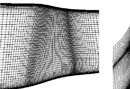
3.4.4 Grid generation ... 44
3.4.5 Finite element (FE) simulations ... 45
CHAPTER 4 MULTIDISCIPLINARY DESIGN OPTIMIZATION (MDO) OF A TRANSONIC FAN BLADE ... 50
4.1 Transonic fan blade design problem statement ... 50
4.2 Aerodynamic optimization ... 53
4.2.1 Problem formulation ... 53
4.3 Multidisciplinary design optimization ... 54
4.3.1 Multidisciplinary feasibility (MDF) ... 54
4.3.2 Filtering approach ... 56
4.3.3 Analytical Target Cascading (ATC) ... 57
4.4 Optimization algorithms ... 65
4.4.1 Simulated annealing (SA) ... 66
4.4.2 Pointer ... 66
4.4.3 MIGA ... 67
4.4.4 NOMAD ... 67
CHAPTER 5 RESULTS AND DISCUSSION ... 69
5.1 Aerodynamic optimization results ... 69
5.1.1 Flow characteristics of reference and optimum blades ... 74
5.2 Multidisciplinary design optimization (MDO) results ... 85
5.2.1 Flow characteristics of reference and optimum blades ... 92
5.2.2 Vibration characteristics of reference and optimum blades ... 99
5.2.3 Structural characteristics of reference and optimum blades ... 100
5.3 A post optimization trade-off analysis ... 102
CONCLUSION AND FUTURE WORK ... 106
BIBLIOGRAPHY ... 110
LIST OF TABLES
Table 2-1: MDO formulations comparative summary (Perez, Liu et al. [23]) ... 9
Table 3-1: Geometrical design variables for section parameterization ... 28
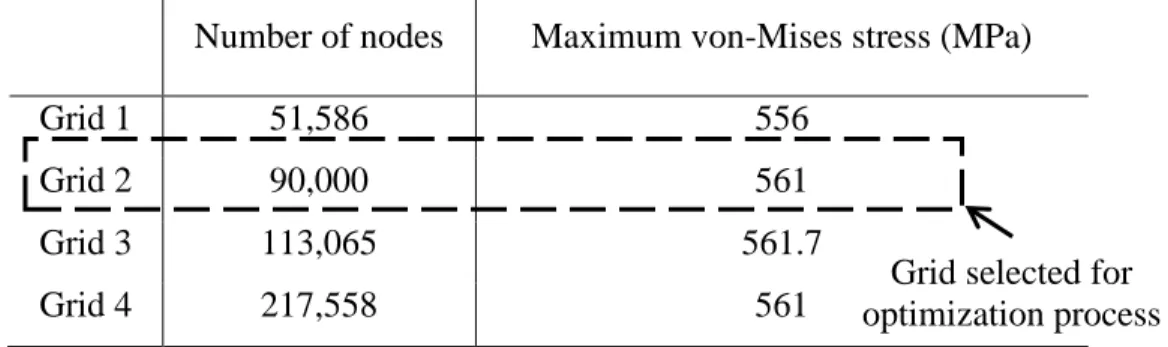
Table 3-2: NASA Rotor 67 grid sensitivity for structural analysis ... 45
Table 3-3: von Misses stress results ... 45
Table 4-1: Geometrical design variables, 𝑥𝑔𝑒𝑜 ... 52
Table 4-2: FDT for original problem (Eq. (8)) ... 62
Table 5-1: List of design variables to optimize Rotor 67 ... 71
Table 5-2: Comparison between NASA rotor 67 and aerodynamic optimization results for 500- evaluations (1-million node grid) ... 72
Table 5-3: List of design variables to optimize Rotor 67 ... 85
Table 5-4: Comparison between NASA Rotor 67 and the MDO framework optimized designs .. 86
Table A-1: Overview of MDO Formulations ... 125
Table A-2: Overview of literature review ... 126
Table A-3: Overview of literature review ... 127
Table C-1: Functional Dependence Table (FDT) for geometrical optimization ... 133
Table D-1: Discipline objective functions and constraints results at the beginning and end of the discipline level optimizations (a) 1st and 2nd outer loops (b) 3rd and 4th outer loops (c) 5th and 6th outer loops (d) 7th outer loops (cont.) ... 135
Table D-1: Discipline objective functions and constraints results at the beginning and end of the discipline level optimizations (b) 3rd and 4th outer loops (cont.) ... 136
Table D-1: Discipline objective functions and constraints results at the beginning and end of the discipline level optimizations (c) 5th and 6th outer loops (cont.) ... 137
Table D-1: Discipline objective functions and constraints results at the beginning and end of the discipline level optimizations (d) 7th outer loops (cont.) ... 138
LIST OF FIGURES
Figure 2-1: AAO framework using the flowchart from Martins and Lambe [16] ... 8
Figure 3-1: Test rotor (Lian and Liou [5]) ... 25
Figure 3-2: NASA Rotor 67 with simple disk ... 26
Figure 3-3: Definition of the suction side and the pressure side of each section [67] ... 28
Figure 3-4: 3D parameter distributions and a fan blade [67] ... 30
Figure 3-5: Modification of thickness distribution near leading edge at 30% span [67] ... 32
Figure 3-6: Meridional view of NASA Rotor 67 ... 33
Figure 3-7: Grid sensitivity between number of nodes and efficiency ... 36
Figure 3-8: Meridional and blade to blade view of computational grid for Rotor 67 ... 38
Figure 3-9: Meridional and blade to blade view of computational grid for Rotor 67 ... 38
Figure 3-10: The comparison of Mach contour of Rotor 67 between (a) Experimental (Strazisar, Wood et al. [123])) (b) Current numerical study (1,000,000-node grid) ... 41
Figure 3-11: The performance comparison of Rotor 67 at design point between experimental (Strazisar, Wood et al. [123]) and current numerical study (1,000,000-node and 150,000 node grids) ... 42
Figure 3-12: Finite element modal of Rotor 67 ... 46
Figure 3-13: von-Mises stress contour of Rotor 67 at design speed ... 46
Figure 3-14: Mode shape of Rotor 67 at design speed (90,000-node grid) ... 48
Figure 3-15: Campbell diagram of Rotor 67 ... 49
Figure 4-1: Multi Design Feasibility (MDF) framework (using block diagram from Martins and Lambe [16]) ... 56
Figure 4-2: Filtering approach or modified MDF framework (using block diagram from Martins and Lambe [16]) ... 57
Figure 4-3: Analytical Target Cascading (ATC) framework (using block diagram from Martins and Lambe [16]) ... 59
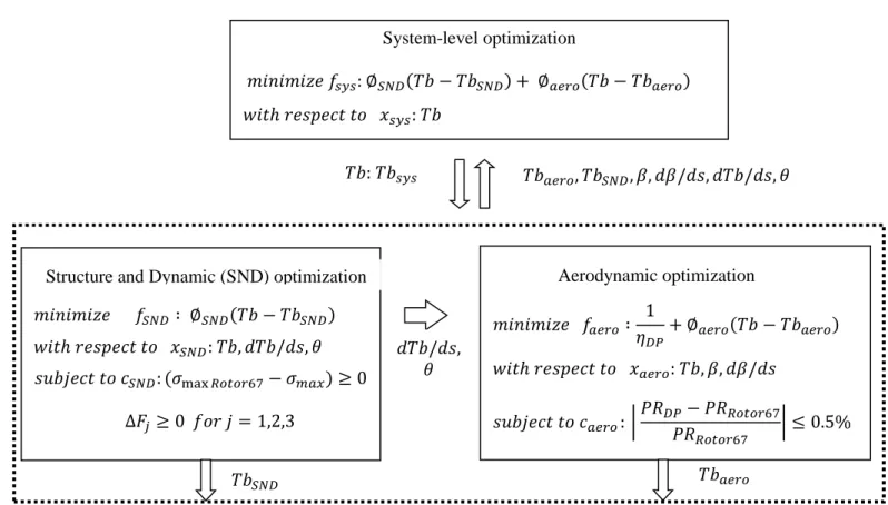
Figure 4-4: The ATC framework for the fan design problem ... 64
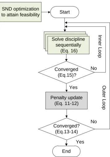
Figure 4-5: Illustration of ATC coordination algorithms for the fan design problem ... 65
Figure 5-1: Geometry sections obtained by aerodynamic optimization and original Rotor 67 ... 73
Figure 5-2: Comparison of efficiency history plot (150, 000-node grid) ... 73
Figure 5-3: Efficiency and pressure ratio versus mass flow rate for aerodynamically optimized solution (1-million node grid) ... 75
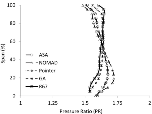
Figure 5-4: Spanwise distributions of the pressure ratio of the Rotor 67 and the optimized blades ... 76
Figure 5-5: Spanwise distributions of the temperature ratio for the Rotor 67 and the optimized blades ... 76
Figure 5-6: Spanwise distributions of the exit flow angle for the Rotor 67 and the optimized blades (downstream the of blade) ... 77
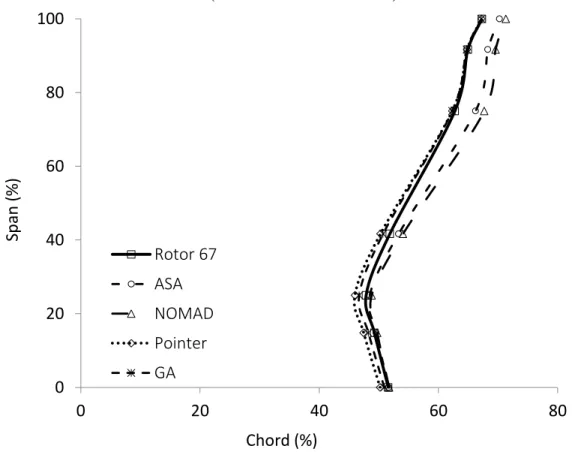
Figure 5-7: Spanwise distribution of maximum thickness location for the Rotor 67 and the optimized blades ... 77
Figure 5-8: Isentropic Mach comparison at 85% span (at design point) ... 79
Figure 5-9: Isentropic Mach comparison at 25% span (at design point) ... 80
Figure 5-10: Mach contour comparison at 85% span (at design point) ... 81
Figure 5-11: Mach contour comparison at 25% span (at design point) ... 82
Figure 5-12 Pressure contour comparison at suction side (at design point)... 83
Figure 5-13: Streamlines close to suction side (at design point) ... 84
Figure 5-14: Comparison of Optimized Rotor 67 geometry sections obtained by MDO formulation and Original Rotor 67 ... 88
Figure 5-15: Efficiency history plot for MDF and filtering approach MDO formulations (150, 000-node grid) ... 89
Figure 5-17: The convergence history plot of improved structure and dynamic (SND) objective
function for inner loop optimizations ... 90
Figure 5-18: The convergence history plot of improved aerodynamic objective function ... 90
Figure 5-19: The convergence history plot of outer loops stopping function (Eq. 13) ... 91
Figure 5-20: Efficiency and pressure ratio versus mass flow rate ... 92
Figure 5-21: Mach number contour comparison at 85% Rotor 67 and optimized blades ... 94
Figure 5-22: Mach number contour comparison at 25% span among Rotor 67 and optimized blades ... 94
Figure 5-23: Mach number contour comparison at 85% span (at design point) ... 95
Figure 5-24: Mach number contour comparison at 25% span (at design point) ... 96
Figure 5-25: Pressure contour comparison at suction side (at design point) ... 97
Figure 5-26: Streamlines close to suction side (at design point) ... 98
Figure 5-27: Campbell Diagram ... 99
Figure 5-28: Blade von-Mises stress contour at pressure side ... 101
Figure 5-29: Simple trade-off study for aerodynamic optimization problem ... 103
Figure 5-30: Simple trade-off study for MDF-MDO optimization problem ... 104
Figure B-1: Plot the pressure ratio (PR) change from iteration to iteration on a log scale, i.e. log (PR [n] – PR [n-1]) for 150,000-node grid ... 128
Figure B-2: Plot the efficiency change from iteration to iteration on a log scale, i.e. log (mdot[n] – mdot [n-1]) for 150,000-node grid ... 129
Figure B-3: Plot the mass flow rate change from iteration to iteration on a log scale, ie. Log (Eff [n] – Eff [n-1]) for 150,000-node grid ... 129
Figure C-1: The sensitivity of the design point efficiency to the geometrical design variables .. 130
Figure C-2: The sensitivity of the design point efficiency, maximum stress, 1st , 2nd and 3rd natural frequencies to the geometrical design variables ... 131
Figure D-1: Spanwise distributions of the temperature ratio for the Rotor 67 and the optimized blades ... 139 Figure D-2: Spanwise distributions of the pressure ratio for the Rotor 67 and the optimized blades
... 139 Figure D-3: Spanwise distributions of the exit flow angle for the Rotor 67 and the optimized blades (downstream the of blade) ... 140 Figure D-4: Spanwise distributions of the maximum thickness for the Rotor 67 and the optimized blades ... 140
LIST OF APPENDICES
APPENDIX A – Literature Review ……….……… 124
APPENDIX B – Parameterization and Analysis Methodologies ……… 127
APPENDIX C – MDO of a Transonic Fan Blade ………... 129
NOMENCLATURE
Symbols𝜎𝑚𝑎𝑥 Von-Mises Stress
𝑥𝑔𝑒𝑜 Geometrical design variable 𝜂 Isentropic efficiency
𝑚̇𝑐 Corrected mass flow P01 Total pressure at inlet
T01 Total temperature at inlet
𝐻01 Isentropic total enthalpy at inlet F1 First dynamic frequency mode F2 Second dynamic frequency mode F3 Third dynamic frequency mode Acronyms
PR Pressure ratio
RPM Revolution per minute
ASA Adaptive Simulated Annealing
SA Simulated Annealing
NOMAD Nonlinear Optimization by Mesh Adaptive Direct Search MIGA Multi-Island Genetic Algorithm
GA Genetic Algorithm
SND Structure and dynamics
MDO Multidisciplinary design optimization MDA Multidisciplinary analysis
IDF Individual Discipline Feasible MDF Multidisciplinary Feasible Design ATC Analytical Target Cascading CO Collaborative Optimization
CSSO Concurrent Subspace Optimization BLISS Bi-Level Integrated System Synthesis RSA Response Surface Approximation EA Evolutionary Algorithm
PS Pressure side
SS Suction side
TE Trailing edge
LE Leading edge
SST Shear Stress Transport
CFD Computational Fluid Dynamics RANS Reynolds-Averaged Navier-Stokes
FE Finite element
APDL ANSYS Parametric Design Language CAD Computer Aided Design
CHAPTER 1
INTRODUCTION
1.1 Background
Transonic fans are extensively used as the first stage of large civil and military aero-engines. They experience high tip velocity in the range of 380–490m/s and as a result the inlet relative Mach number is high, up to 1.7. Nowadays, an efficient transonic fan has total pressure ratio in the range of 1.5-2.2. The modern transonic fan designs have reached a high level of performance, making further improvements a challenging task. Nevertheless, a small increment could lead to significant savings in the fuel cost and reduced environmental impact, which are one of the prime intentions of the aero-engine manufacturing industry [1-3].
Modern transonic fan design requirements are evolving towards an increase in fan diameter and a higher bypass ratio to improve the efficiency and reduce the noise emission. This results in more multifaceted geometries, consequently extremely complex detrimental flow structures including shock, shock-boundary layer interaction, secondary flows, etc. Furthermore, the transonic fan blade aerodynamic design is also affected by the mechanical requirements such as maximum stress, vibration modes, etc.
1.2 Human driven fan design process
The fan design process is explained here in its most basic form as per information available in the literature and communication with engineers from our industrial partner.
The transonic fan blade design is inherently a multidisciplinary process which requires the involvement of several disciplines including aerodynamics, structures and vibration. Each discipline is responsible for different performance parameters of fan blade design. Moreover, disciplines exchange information with each other at different stages of the design process which increases the complexity of the process. Furthermore, a traditional three-dimensional fan blade design technique is based on the personal expertise. In most situations, designers have to perform manual modifications to the blade shape based on their judgment and analysis. Basically, the designers use a “trial-and-error” approach, where blade geometry is set up, analyzed and then modified repeatedly towards the optimal design.
The design process starts with the aerodynamics discipline as non-linear transonic flows are very sensitive to the fan blade shape. The aerodynamics discipline primarily focuses to improve the efficiency or to reduce the losses. The high performance aerodynamic fan design geometry is transferred to the structural and vibration disciplines in order to check the mechanical integrity in terms of the maximum allowable stress level, safety margin and excitation frequencies that should be avoided in the engine running range. If the mechanical requirements are not met then the geometry is sent back to the aerodynamics discipline. This often results into several back and forth iterations between the aerodynamics and the mechanical analyses in order to achieve a satisfactory compromise in the fan blade design. So, the classical fan design is intrinsically a sequential iterative process which is also expensive in terms of the computational resources and design cycle time.
Usually, a fan blade geometry definition roughly includes 15-20 two-dimensional sections and 20-25 geometrical design parameters per section, which together give a total of 200-500 parameters. Moreover, every discipline is using different commercial and in-house softwares to perform relevant analyses. This large number of design variables and the variety of analyses performed with the intensive computational tools increase the complexity of handling the fan design process. Consequently, in relation with the increased fan shape complexity, the fan design iterative process has become more and more difficult to converge, and requires more iterations and more compromises between disciplines.
1.3 Need of multidisciplinary design optimization (MDO) methodology
In recent years, the turbomachinery industries have integrated high fidelity computational tools such as Computer Aided Design (CAD), Computational Fluid Dynamics (CFD) and Finite Element Analysis (FEA) solvers in order to understand the complex flow structures and intricate mechanical characteristics in relation with the performance of the components.
Despite these modern solvers and the availability of efficient optimization algorithms, fan blade shape optimization is not applied intensively in the industry due to a number of factors. First, the performance of a transonic fan blade is very sensitive to the shape changes so the geometry must be parameterized with a suitable number of parameters. Moreover, the characteristic functions of a fan design problem are often multimodal and nonlinear because the flow field is governed by the nonlinear Reynolds-Averaged Navier-Stokes partial differential equations. Furthermore,
several constraints from multiple disciplines, such as mass flow rate, maximum stress, and others make the optimization a difficult task.
In addition, the fan blade design involves multidisciplinary optimizations conducted sequentially with “performance” compromises in search of an overall optimal, or at least a good design. In addition, a blade that is optimized or traded at one discipline might not satisfy the requirements of the other disciplines. Mostly, improvement in one design requirement results in performance degradation of the other requirements. In general, the blade design process consisting of defining a geometry that meets many rigorous requirements is a challenging task.
Thus, there is an essential need of a methodology that can address all above design requirements and designers’ needs by providing a computational framework for the interaction of multi-disciplines. It is believed that multidisciplinary design optimization (MDO) technologies can help to solve the complex fan design problem. In essence, the MDO methodology aims to subdivide a complex design problem into optimization sub-problems each with respect to the design variables that are relevant to a discipline specialist and to manage to the strong interactions between several disciplines involving a multitude of constraints, design variables and objectives. This further leads to task parallelization to efficiently utilize the available computational resources.
MDO methodology has been successfully implemented in numerous engineering domains such as aircraft design, wing design, automobile, etc. However, applying MDO in transonic fan blade design problem is still a challenging task due to many reasons. First, MDO is computationally more expensive in comparison to the sum of the single discipline optimizations. For example, it might be practically difficult to handle the analysis of all the disciplines and their coupling under a single optimizer while using a variety of intensive computational software with diverse analyses times and a large number of design variables. Furthermore, a single discipline optimization may have only one objective function whereas MDO based design optimization can involves several multi-objective optimizations. Secondly, the organizational complexity is also a challenge for MDO implementation in fan design problem, especially when large numbers of design variables are involved. For example, different computationally intensive analyses can run on multiple machines at various physical locations. For this reason, an accurate representation of the multidiscipline interactions and the real engineering team work must be understood [4, 5].
Finally, although several MDO frameworks are available in the literature to express a design optimization problem, the MDO implementation is entirely problem dependent, which requires not only comprehension of the problem particulars, but also involves a deep understanding of the underlying complexity of MDO frameworks and the specificities of optimization algorithms.
1.4 Motivation and objectives
The global objective of the present work is to develop, exploit and propose various approaches for the multidisciplinary design and optimization of the transonic fan blades.
The specific objectives can be defined as:
Develop an automatic integrated analysis process based on CAD-CFD-FEA for transonic fan blade multidisciplinary analyses. The CAD model will be parameterized and all the analyses modules will seamlessly link with the CAD model to perform the design evaluations.
Exploit the integrated analysis system to understand its characteristics and identify the possible avenues for the problem decomposition.
Propose, implement and compare MDO based design approaches that are tailored to the transonic fan design process, to optimize aerodynamic design while respecting stress and vibration constraints.
1.5 Outline of the thesis
This thesis contains five chapters. Following the above introductory section, chapter 2 provides a literature review of the available MDO formulations, their comparisons and MDO implementations in aeronautics and propulsion domain. This chapter also covers the recent progress in transonic fan design optimization. In chapter 3, the discipline analyses modules used for the present research are presented, followed by the MDO methodology in chapter 4. Chapter 5 gives the results and discussion followed by the conclusions and future work.
CHAPTER 2
LITERATURE REVIEW
This literature review covers the advanced techniques used for the design and optimization of transonic compressor blades. This chapter is divided into three sections. The first section provides a general description of multidisciplinary design optimization (MDO) formulations developed in the past decades along with the comparison of the formulations available in literature and their implementation in aeronautics and propulsion industries. The second section describes the blade design optimization which covers the blade geometry parameterization, performance evaluation, optimization algorithms, and highlights of adopted fan blade design methodologies in literature. A brief overview of recent progresses on axial transonic fan and compressor blade optimization is also included in this section. The final section provides a brief summary of literature review, which directly links the conclusive steps to the methodology adopted in this thesis.
2.1 Multidisciplinary design and optimization (MDO)
Multidisciplinary design optimization (MDO) problems typically involve a large number of design constraints, variables and objectives from different disciplines. For MDO problems, the most important task is the seamless linkage of various system models and optimization algorithms. Furthermore, the design requirements must be defined and then formulated mathematically, as objective and constraints functions.
MDO provides an opportunity to find the optimal solution of a system by establishing the interaction between the various disciplines. However the solution is not likely the best solution for a single discipline.
The selection of an appropriate MDO formulation has a huge importance to come up with an efficient solution of the design problem. In the following subsection, we introduce MDO formulations with respect to problem decomposition and architecture. After that, published comparative studies of existing MDO formulations are analyzed.
2.1.1 Problem decomposition and architecture
A large system is described by a large number of design variables and is usually computationally too expensive to be optimized for all the variables at the same time. One way to deal with this
kind of problem is to decompose the system into subsystems, which can be optimized in parallel. There can be «natural» decompositions of a system into subsystems using hierarchical, non-hierarchical and hybrid approaches. The non-hierarchical approach allows communication between below and above disciplines. The non-hierarchical approach allows communication among any disciplines and the hybrid approach is the combination of hierarchical and non-hierarchical approaches.
The MDO formulations can be classified on the basis of the disciplines interactions as ‘single-level’ or ‘multi-level.’ The single-level formulations such as All-at-Once (AAO) [6], Individual Discipline Feasible (IDF) [6-8], Multidisciplinary Feasible Design (MDF) [6, 7, 9] involve a single optimizer.
The multi-level formulations require an optimization framework with several interacting optimizers. Among multi-level formulations we can cite Collaborative Optimization (CO) [10], Concurrent Subspace Optimization (CSSO) [11, 12], Bi-Level Integrated System Synthesis (BLISS) [13] and Analytical Target Cascading (ATC) [14, 15]. A brief description of the work presented in all above cited references is listed in Table A-1(Appendix-A).
While defining an optimization problem, the first step is to specify the objective function(s), and the design variables with bounds and constraints. Then the optimization formulations can be stated. Before discussing the details of the MDO formulations employed in this work, a general form of problem formulation such as AAO (in the notation given by Martins and Lambe [16]), is taken as a baseline: maximize 𝑓0(𝑥, 𝑦) + ∑𝑁 𝑓𝑖(𝑥0, 𝑥𝑖, 𝑦𝑖) 𝑖=1 (1) 𝑤𝑖𝑡ℎ 𝑟𝑒𝑠𝑝𝑒𝑐𝑡 𝑡𝑜 𝑥, 𝑦̂, 𝑦, 𝑦̅ 𝑠𝑢𝑏𝑗𝑒𝑐𝑡 𝑡𝑜 𝑐0(𝑥, 𝑦) ≥ 0 𝑐𝑖(𝑥0, 𝑥𝑖, 𝑦𝑖) ≥ 0 for i= 1,…, N 𝑐𝑖𝑐 = 𝑦̂𝑖− 𝑦𝑖 = 0 for i= 1,…, N 𝑅𝑖(𝑥0, 𝑥𝑖, 𝑦̂𝑗≠𝑖, 𝑦̅𝑖, 𝑦𝑖) = 0 for i= 1,…, N
where, x is a vector of design variables. y is a vector of coupling variables or output from discipline analysis. f is an objective function, c is a vector of design constraints. cc is a vector of consistency constraints. R is a set of governing equations of a discipline analysis in residual form or discipline analysis constraints. 𝑦̅ is a vector of state variables or variables used inside only one-discipline analysis. N is the number of disciplines. The subscript 0 represents those functions or variables that are shared by more than one discipline. The subscript i represents functions or variables that apply only to discipline i. The cap symbol “^” represents independent copies of variables distributed to discipline.
The formulation given in Eq.(1) includes all the coupling variables, copy of the coupling variables, constraints, consistency constraints, state variables and residual of governing equations. AAO solves MDO problem in a straightforward way by giving control to a system-level optimizer. Some authors state AAO as Simultaneous Analysis and Design (SAND) [9, 17]. Figure 2-1 represents the AAO problem framework [16].
In Figure 2-1, a type of flowchart is used to describe the AAO framework. The components (in this case discipline analyses) are placed in diagonal. The special rounded rectangular component or driver controls the iterations. The component is used to process the data. The data flow is displayed in thick gray line. The component takes the data input from the vertical line and output data in the horizontal line. Therefore, the connections flow above the diagonal flow from left to right and top to bottom, and the connections below the diagonal flow from right to left and bottom to top. An off-diagonal node in the shape of a parallelogram is used to label the data. The external inputs and outputs are placed on the top row and the leftmost column respectively. The thin black lines represent the process flow. The superscript * represents the function or variables at their optimal value. Any block referring to discipline i denote a repetitive pattern for every discipline. A numbering system is used to show the order in which components are executed. The AAO formulation given in Eq.(1) is used to derive the selected formulations for this work. Due to its nature, several simplifications can be made to the general formulation when stating the transonic fan design optimization problem; this is presented in the following chapter.
0, 2-1: Optimization x*, y* 1: x,y,yˆ x(0), yˆ(0), y(0),y¯ (0) 1: Function 2: Ri 2: f,c, cc
x0, xi, yi,yj≠ y¯i
1 : Residual i
Figure 2-1: AAO framework using the flowchart from Martins and Lambe [16]
2.1.2 Comparison of MDO formulations
The purpose of this section is to review and analyze the published comparative studies on the existing MDO formulations which will further help to select suitable MDO formulations for the transonic fan blade design problem.
A number of comparative studies have been reported in the literature to evaluate the capabilities and effectiveness of each proposed MDO formulation, as well as their limitations for a given design problem. The evaluation of different MDO formulations can take into consideration the optimization and formulation aspects [18-24].
Hulme and Bloebaum [20] compared various MDO formulations including the MDF, IDF and AAO on five analytical examples of varying size and complexity. Metrics such as the number of iteration cycles, design variables and the accuracy are the basis of this evaluation. Based on these metrics they concluded that MDF is the “best” solution for all the test problems with the smallest number of executions The same metrics are used by Chen, Zhang et al. [19] to evaluate CO, CSSO, and BLISS on two application examples. They recommended CO for systems with little interaction between disciplines, BLISS for highly coupled system and CSSO formulation only for small-scale systems.
Another comparative study was carried out by Perez, Liu et al. [23] with a set of metrics (see Table 2-1), for both formulation considerations and optimization performance criteria. They determined the characteristics of each formulation (MDF, IDF, CO, CSSO, and BLISS) by
analyzing two test cases based on the proposed metrics. A summary of this work is presented in Table 2-1.
MDF is found to be the most accurate formulation as it performs the full disciplinary system analysis, but its efficiency suffers with increase in complexity. IDF offers an alternative to MDF when portability analysis is not an issue. The BLISS formulation accuracy is similar to centralized formulations but computationally more expensive. Its main advantage lies in the portability for distributed analyses. CO shows best choice for conceptual design process due to the high probability to fit in the existing system and its simplicity makes it easy for modification. However, CSSO is found efficient for small scale problems or analytical formulations since system approximation increases the complexity of implementation. Moreover, BLISS provides certain amount of portability and suitable for the problem where highly coupled systems analysis is available.
Table 2-1: MDO formulations comparative summary (Perez, Liu et al. [23])
Accuracy Efficiency Transparency Simplicity Portability
Best MDF IDF MDF MDF CO
IDF BLISS IDF IDF CSSO
BLISS CSSO CO CO BLISS
CO CO CSSO CSSO IDF
Worst CSSO MDF BLISS BLISS MDF
The comparison of ATC with other MDO formulations is not often available in literature yet. However, ATC and other multi-level frameworks such as CSSO, CO and BLISS are compared by De Wit and van Keulen [24]. These frameworks are studied on the same design optimization problem with a gradient-based optimizer and are compared to AIO solution in terms of the number of function calls and discipline evaluations. This study shows that CO and ATC performed equally well in terms of number of function calls. It is also found that, ATC with other multi-level frameworks are not competitive with single-level framework in terms of function calls and discipline evaluations.
In general, it is difficult to draw a definitive conclusion between the existing MDO formulations using the current literature available in the references (see Refs. [18-23]) due to the reason that if one MDO framework is suitable for one system, it is not necessarily a good choice for other systems because all systems have different attributes such as different objectives to achieve with different number of design variables, limits of constraints and sequences of disciplines, which cause differences in the level of success.
2.1.3 MDO implementation in aeronautics and propulsion
The application of MDO formulation within the aeronautics and propulsion fields involves several subsystems/disciplines: for example aerodynamics, structure and dynamics, and potentially many other disciplines. In literature, the most commonly found applications of MDO are about design of aircraft [25-27], rotorcraft [28-30], wind turbines [31], spacecraft [32, 33] and propeller [34].
A Boeing 747-400 aircraft was redesigned by Allison, Walsh et al. [35] by employing AIO and ATC product development formulations. The objective was to minimize the gross take-off weight (GTOW) with satisfactory performance constraints for takeoff, cruise and climb mission conditions. ATC performed well in the system oriented design environment and improved the objective function by 17% as compared to AIO. The authors concluded that for some cases ATC requires more computation time but it offers a flexible design space exploration that helps to find the global optimum.
Several researchers conducted the aerodynamics and structural optimization to redesign a helicopter rotor blade (see Refs. [30, 36-38]). Lee and Hajela [38] used a Genetic Algorithm (GA) in a decomposition-based approach for the design of a helicopter rotor blade to minimize the vibration at the rotor hub. They found that the decomposition-based approach is more effective as compared to the AIO formulation.
Tribes, Dubé et al. [39] executed a simple wing design MDO optimization problem based on simplified aerodynamics and structure analyses by using two single-level MDO formulations Distributed Analysis Optimization (DAO), Fully Integrated Optimization (FIO) and two bi-level MDO formulations including Inexact Penalty Decomposition (IPD) and a new proposed formulation called Distributed Optimizations (DO). The design problem involves the
aerostructral coupling as well. The authors concluded that for this wing design problem DO performs well but DAO is found to be more efficient as compared to FIO, IPD and DO. A requirement to study the influence of the number of design variables on the performance of different MDO formulations is highlighted.
A multi-layer optimization of disk and blade, was performed by Wang, Jia et al. [40]. Multilevel MDO formulations were implemented in three ways, which include BLISS 2000 two layers and two subsystems (aerodynamics and structure), BLISS 2000 two layers and triple-subsystems (aerodynamics, blade and disk structure) and BLISS 2000-CO formulations for three layers (structure optimization further subdivided into blade and disk optimization). A total of 13 geometrical design variables, 8 stress reliability constraints and 1 radial elongation constraint were considered. It is observed that the two layer MDO formulations perform better as compared to the three-layer MDO formulations caused by the additional calculation between the second and third layer. Moreover, Allison, Kokkolaras et al. [41] reported that CO could be nested within ATC.
Recently, the similar multi-level MDO frameworks were applied by Yang, Chen et al. [42] for turbine blade design problem to perform aerodynamics and thermal optimization. To maximize the efficiency and minimize the weight, a single weighted objective was considered along with the maximum blade temperature, mass flow rate, maximum stress and blade tip elongation constraints. They concluded that CO performance may be affected by the weighted sum to handle the two objectives. However, BLISS 2000 was found more robust as compared to CO; and a need for other multi-objective approaches is also mentioned.
In summary, MDO frameworks are powerful tools for designing aircraft components, as they allow the consideration of various subsystem requirements during the whole design process. It is also observed that not many studies presented MDO application for turbomachinery high-fidelity design problems especially the transonic fan and compressor design problems.
2.2 Blade design optimization
The turbomachinery automatic blade design optimization process mainly consists of integration of the blade geometry parameterization, performance evaluation (flow, stress and dynamics analyses) and optimization algorithms. In addition, to improve the performance of automatic
design optimization process, various methodologies are adopted by different researchers such as surrogate model, adjoint method, etc., and will be reviewed in the following subsections.
2.2.1 Blade geometry parameterization
Transonic fan blade performance is sensitive to its shape and thereby the appropriate choice of design parameters and the approach to modifying the design parameters are essential and determine by the blade geometry parameterization method. A blade parameterization with minimal parameters is desirable during the design as it allows to efficiently explore a less intricate design space and to obtain directly a smooth blade shape without further geometrical operations. Hence, the blade geometry parameterization plays an important role in turbomachinery blade design optimization.
The most popular turbomachinery blade geometry parameterization techniques are B-spline and Bézier curves. The B-spline parameterization were implemented by Oyama, Liou et al. [43, 44]; Lian and Liou [45] and Pierret, Coelho et al. [46] to parameterize a transonic NASA Rotor 67 fan blade. The Bézier curves were used by Buche, Guidati et al. [47]; Benini [48]; Arens, Rentrop et al. [49] and Lotfi, Teixeira et al. [50] to parameterize a turbomachinery blade. Furthermore, the higher order sets of polynomials were employed by Chen, Zhang et al. [51] to construct a transonic compressor blade. The blade perturbation parameterization approach by using Hicks– Henne polynomial function and its variants was employed by Wang, He et al. [52]. They have used a total of 143-design variables to parameterize a Rotor 67 blade. Thus, either approach takes at least 20 parameters to define a single two-dimensional section. In most situations, more than 100 parameters are needed to generate a complete three-dimensional blade geometry. Recently, blade geometry changes such as the lean (moving the blade section in the circumferential direction) and sweep (moving blade in the axial direction) [53-55], the maximum thickness location along chord [56], the camber distribution [57], the skew (stacking line in the rotational direction) [58] and the solidity [48] have been used with some success in order to reduce the number of design variables [51, 59-66].
Recently, Lupien [67] has presented a three-dimensional parameterization approach (see details in Section 3.2) to represent and optimize a transonic fan blade with fewer design variables which is favorable for optimization. The parameterization software also ties the geometry to
computer-aided design software (CATIA), in order to share a common model for structure and dynamic analyses. This parametrization has been adopted in this thesis work.
2.2.2 Performance evaluation
In the design process, the performance of turbomachinery blade is evaluated at different levels of fidelity to achieve the full engine design. For an entirely new style engine, the first step is to employ the empirical relations in order to establish the compressor configuration. However, for a variant of an existing engine design, an accurate computational solver is required to evaluate the detailed performance of a modified geometry [3]. For the current thesis work, the following performance evaluation analyses have been considered.
2.2.2.1 Flow field analysis
The optimization of transonic fan and compressor blade consists of modifying the blade to achieve the targets such as mass flow rate and pressure ratio while minimizing the undesirable flow features such as high incidences, high shock losses, large blade passage flow separations, etc. Thus, fully three-dimensional CFD methods are needed to evaluate these effects.
Various commercial and in-house softwares were developed for flow analysis of turbomachinery blade. In this regard, TRAF3D [68, 69], a three-dimensional Navier-Stokes based code (see Refs. [5, 44, 46, 70-74]) and ANSYS commercial software (see Refs. [48, 75-77] are used by many research groups for transonic fan and compressor design optimization. Due to its wide range of features, ANSYS has become a popular choice for transonic fan and compressor manufacturer and is also utilized in the current thesis work.
2.2.2.2 Stress and dynamic analyses
The high rotational speed of the fan or the compressor rotor adds the complexity by means of static stress and vibration, into the blade design optimization problem. Therefore, finite element (FE) method is used to evaluate the mechanical requirements. The FE analysis commercial software ANSYS was used in many aero-mechanical optimization of turbomachinery blades (see Refs. [5, 65, 75, 78, 79]).
2.2.3 Optimization algorithms
A number of optimization techniques for efficiently solving engineering design problems are available in some of the classical text books like Fletcher [80], Gill et al. [81], Rao [82], Moré, Wright et al. [83]. In general, the optimization algorithms are classified into gradient-based and non-gradient based methods and an overview of this subdivision is presented in the following section.
2.2.3.1 Gradient-based methods
The optimization process using Gradient-based methods requires derivative information for the objective and constraint functions to obtain a direction of search. The performance of a gradient-based method strongly depends on the initially supplied values for the design variables. These methods are well suited for continuous design space but may not be appropriate for searching the global optimum of a multi-modal problem [84].
Gradient-based methods have demonstrated their ability to solve engineering design optimization problems such as wing design [85], aircraft configurations [86] and turbomachinery blade design [52, 87-89]. Burguburu, Toussaint et al. [89] used gradient-based methods to improve the efficiency of a transonic compressor while maintaining the pressure ratio. The three-curvature control points on suction side were taken as design variables.
Although, the gradient-based methods are rapid optimization methods and require a small number of evaluations as compared to non-gradient based methods, but they can easily be trapped by local minimum. Due to this reason, these methods are also recognized as local optimizers [90].
2.2.3.2 Non-gradient methods
The Non-gradient methods do not require any derivatives of the objective function in order to search for an optimum. One of the advantages of these methods is that they are more likely to find global optimum and not be trapped by a local optimum. These methods are well suited for nonlinear, multimodal problems and discontinuous design space. However, non-gradient-based methods require a large number of evaluations and result into relatively high computational cost. A number of methods exist in this group such as the evolutionary algorithm, particle swarm, simulated annealing, etc. Among them, the evolutionary algorithms are the most common choice
to solve the design optimization of transonic compressor blade problem (see Refs. [5, 43, 48, 73, 75, 78, 91-95]).
In addition, each optimization algorithm has its own strengths and weaknesses. A commonly reported opinion is that “no-single optimization algorithm is suitable for all problems." For this reason, in a preliminary study, it is valuable to compare several optimizers.
2.2.4 Blade design methodologies
A number of studies are published to redesign transonic fan and compressor blade by using surrogate models, adjoint method and inverse design approach. The detail of all these investigations is discussed below.
2.2.4.1 Adjoint method
An adjoint method computes accurate gradient for the governing equations and provides sensitivities of the objective and constraint functions with respect to the design variables. It can be coupled with gradient-based optimizers and has been adopted by many researchers in turbomachinery design (see Refs. [52, 88, 96-99]).
Recently, Luo, Zhou et al. [88] implemented an adjoint method on RANS equations by using the SST turbulence model to perform single (at design point) and multipoint (at the design point, near choke and near stall) design optimizations to improve the adiabatic efficiency of NASA Rotor 67 while having the mass flow rate and total pressure ratio under constraints. The single objective optimization has improved adiabatic efficiency by 1.10% but reduced the total pressure ratio. The multipoint optimization gives higher adiabatic efficiency with no reduction in the total pressure ratio. However the improvement in the adiabatic efficiency is slightly smaller than the single objective gain.
However, the development cost of adjoint codes to solve the system of equations for the complex, three-dimensional flow with many unknowns, might be the main shortcoming [90]. Moreover, at the present time, adjoint methods are not readily available in commercial softwares such as CFX or Fluent.
2.2.4.2 Surrogate models
A surrogate model is often used in MDO system to get relatively good high-fidelity model information throughout the optimization without computational expenses associated to a high-fidelity analysis. The surrogate models or Meta-models are analytical equations that approximate outputs of the intricate systems that are built by providing a limited set of computational expensive simulations. Surrogate-based optimization approaches have been implemented and tested by various researchers on computationally expensive problems such as turbomachinery design problems due to their inherent advantages.
Surrogate models applications include Design of Experiments (DoE) with Response Surface Approximation model (RSA) by Myers and Montgomery [100], Artificial Neural Networks (ANN) by Turban and Frenzel [101], Kriging Meta-model (KRG) by Martin and Simpson [102], Radial Basis Neural Network (RBNN) by Orr [103] and weighted average surrogate model based on RSA, KRG and RBNN by Goel, Haftka et al. [104]. Goel, Haftka et al. [104] concluded that the weighted average surrogate model is robust and better as compared to the other best individual surrogate models for both low and high dimensional problems regardless the number of points used in the model response.
Numerous researchers ([5, 46, 60, 75, 105, 106]) have optimized the transonic fan and compressor blade in a multidisciplinary context by using several different surrogate models. One of the possible reasons of surrogate models selection is that the surrogate models might be simple and could help the optimizer to optimize the design problem with less computational time. However, the surrogate models might not be able to capture the information for a large design space and unable to predict the optimum design with accuracy as compared to the high-fidelity solutions.
2.2.4.3 Inverse design method
The turbomachinery blade design performance improves during an optimization in terms of efficiency, pressure ratio, stress, vibration, etc., by varying geometrical design parameters or blade geometrical dimensions. Conversely, in the inverse design methods, the blade is redesigned by aiming prescribed flow characteristics such as blade pressure distribution, circulation, velocity and varying local geometrical parameters.
In the last two decades a number of papers were published on the inverse design approach on the transonic axial compressor (see Refs. [57, 107-114]). In this context, Tiow, Yiu et al. [115] redesigned NASA Rotor 67 by improving the incidence near the hub and shock formation near the tip with change of static pressure loading. Moreover, Geng, Chen et al. [95] applied a simple method of redesigning the pressure (or Mach number) distribution on the suction side of NASA Rotor 37 by controlling the shock to enhance the adiabatic efficiency. This method was able to reduce the shock strength level and decrease the boundary layer separation loss to increase the efficiency.
However, inverse design method is struggling in establishing criteria for the optimal loading distribution and mechanical constraints implementation due to the presence of secondary flow. A lot of vision is required to modify the mechanical and geometrical parameters for the velocity variations [90].
2.2.5 Recent progress
Fan design shares many similarities with the design of a single stage axial compressor. So, in this section, the recently published studies on transonic compressor or transonic fan blade design problems are presented. The section is subdivided into three subsections to discuss aerodynamics optimization, aerodynamics-structure optimization and aerodynamics-structure-dynamic optimization. An overview of this recent progress is tabulated in Table A-2 and Table A-3 (Appendix-A).
2.2.5.1 Aerodynamics optimization
In recent years, several studies have focused on the aerodynamics design optimization of transonic fan and compressor blade. The optimization problem is most commonly targeted to improve the efficiency or reduce the losses subject to some required constraints, such as mass flow rate, pressure ratio and others (see Refs. [43, 44, 59, 62, 71, 87, 88, 116]). Lee and Kim [87] optimized a compressor blade by using a gradient-based optimization method. Their objective was to minimize the aerodynamics losses/maximize the efficiency by taking a stack line as a variable. Another single objective optimization to improve efficiency of NASA Rotor 37 is executed by Jang, Samad et al. [62] by taking sweep, lean and skew design variables. A
conclusion has been made that among these design variables skew is the most effective for efficiency enhancement.
In the past, the turbomachinery design and optimization were limited to fewer design variables due to computationally expensive three-dimensional flow analyses. In recent years, analyses tools, optimization software and blade parameterization have improved to produce impressive results such those from Oyama et al. [43] to redesign NASA Rotor 67 with 56-design parameters. They successfully developed a high-fidelity numerical aerodynamics optimization tool for transonic compressor blade design by using three-dimensional Navier-Stokes solver (TRAF3D). In this tool, an evolutionary algorithm named real-coded adaptive range genetic algorithms (ARGA) was adopted. The entropy production was reduced by 19%, which further led to a significant gain in efficiency of 2% as compared to baseline design.
After that, Oyama, Fujii et al. [44] added an additional thickness constraint but did not get a significant reduction in entropy due to tight constraints. They recommended considering a multi-objective and multidisciplinary (aerodynamics, stress and dynamic) design optimization in order to achieve a better blade design.
In all of above cited works, the blade aerodynamics is optimized on a single objective, i.e. either aerodynamics loss or efficiency at design point. However, a compressor has to satisfy design requirements not only at the design point but also at the off-design points, as an aircraft engine operates over a large range of operational regimes. Thus, a transonic fan and compressor aerodynamics design optimization problem involves multiple measures of performance or multi-objective such as design point efficiency, stall margin, choke margin, total pressure ratio, etc., in order to get the trade-off solutions between the contradicting design goals. The multi-objective optimizations provide insight to the engineering design problem that further helps to achieve many Pareto-optimal solutions (a set of compromise solutions) and more information to the designers. A number of investigations dealt with the multi-objective aerodynamics transonic fan and compressor design optimization (see Refs. [48, 70, 71, 93, 94, 117-119]). A multi-objective optimization was performed by Benini [48] to maximize the efficiency and pressure ratio of NASA Rotor 37 while keeping mass flow rate under constraint. A higher-pressure ratio helps to reduce the number of stages which further leads to reduce the engine weight. An evolutionary algorithm [120] was used for optimization. The overall efficiency was improved by 1.5% without
changing the pressure ratio. However, another optimal blade was obtained with a 5.5% pressure ratio rise and a 0.8% efficiency drop.
More recently, the enhancement of the design performance (peak efficiency) and off-design performance (stall margin) of NASA Rotor 67 were considered by Okui, Verstraete et al. [71]. In this optimization the choked mass flow was constrained. The optimization was conducted in two stages: first a meta-model coupled with artificial neural network (ANN) and then with a differential evolution (DE) method. A 0.6% efficiency improvement was obtained with backward sweep together with S-shaped camber line and chord length movement. Stall margin is slightly improved.
Another way to handle the multi-objective optimization problem is to reformulate the multiple objectives into a single objective function mostly by weighted sum method (see Refs. [46, 88]). However, it is difficult to set appropriate weights for different objectives as it requires insight information of the inner relations.
2.2.5.2 Aerodynamics and structure optimization
Aerodynamics optimization in turbomachinery blade design problem is often performed with structural constraints or objectives such as maximum stress, weight, safety factor, etc. (see Refs. [5, 73, 77, 105]).
An aero-structural optimization that focuses on maximizing the pressure ratio and minimizing the weight was conducted by Lian and Liou [5]. This optimization included a stress safety factor (ratio material yield stress to the equivalent stress) and a mass flow rate constraint. The high fidelity analysis tools, the genetic algorithms and response surface approximation were used. As compare to the baseline Rotor 67 the optimized design had 1.88% rise in the pressure ratio and 5.36% reduction in the weight while stratifying the aero-structural constraints. In addition, the maximum von-Mises stress was located at the root of the blade.
The enhancement of safety factor along with the efficiency improvement was studied by Kang, Park et al. [105] on a single-stage transonic axial compressor. Both objectives were reformulated into a single objective function by giving certain weights. The genetic algorithm (GA) was applied to explore the Pareto front and to find the maximum value of the objective function. After that gradient-based optimization was implemented on the final design to improve the accuracy of
![Figure 2-1: AAO framework using the flowchart from Martins and Lambe [16]](https://thumb-eu.123doks.com/thumbv2/123doknet/2341630.33977/27.918.192.727.104.364/figure-aao-framework-using-flowchart-martins-lambe.webp)