HAL Id: hal-01983376
https://hal.archives-ouvertes.fr/hal-01983376
Submitted on 23 Jan 2019HAL is a multi-disciplinary open access archive for the deposit and dissemination of sci-entific research documents, whether they are pub-lished or not. The documents may come from teaching and research institutions in France or abroad, or from public or private research centers.
L’archive ouverte pluridisciplinaire HAL, est destinée au dépôt et à la diffusion de documents scientifiques de niveau recherche, publiés ou non, émanant des établissements d’enseignement et de recherche français ou étrangers, des laboratoires publics ou privés.
sandwich structures
Bruno Castanié, J.-J. Barrau, J.-P. Jaouen
To cite this version:
Bruno Castanié, J.-J. Barrau, J.-P. Jaouen. Theoretical and experimental analysis of asymmetric sandwich structures. Composite Structures, Elsevier, 2002, 55 (3), pp.295-306. �10.1016/S0263-8223(01)00156-8�. �hal-01983376�
THEORETICAL AND EXPERIMENTAL ANALYSIS OF
ASYMMETRIC SANDWICH STRUCTURES
B. Castanié* J-J. Barrau ** J-P. Jaouen†
* Laboratoire Structures, Supaéro, BP 4032, 31055 Toulouse Cedex 4
** LGMT, Bat 3PN, Université Paul Sabatier, 118 Rte de Narbonne, 31062 Toulouse † Eurocopter France, 13725 Marignane
Corresponding author : bruno.castanie@supaero.fr, Fax : (33).5.61.55.81.78.
Abstract.
A new technology, known as asymmetric sandwich structures is now used for the design of lightweight structures. Static failure tests demonstrate the high performance of this technol-ogy and show its original mechanical behavior. Due to this complex mechanical behavior, the use of nonlinear finite element models in the pre-project phase is a long, expensive process. This paper presents a specific theory which enables faster design loops. The theory is first val-idated by comparison to numerical models and is then used to correlate structural tests on asymmetric sandwich plate under combined compression/shear loadings. The tests were con-ducted on original test equipment designed to investigate the capabilities of this technology.
Keywords.
Asymmetric sandwich structures, shear/compression testing, geometrically nonlinear analysis, helicopter composite structures.
1-Introduction.
Sandwich structures exhibit static properties like high stiffness-to-weight ratio and high buckling loads which are of great importance in the aeronautics field. Although their properties have been known since the thirties, the current applications remain limited to secondary
struc-tures such as surface control or floor panels (Amstrong et Al [1]) or to a handful number of pri-mary aircraft structures like the Beechcraft Starship (Hooper [2]). In fact, the limitations are linked to the cost and reliability of manufacturing (Sheahen et al [3]) and to the lack of knowl-edge of the effects induced by impact damages (drop in strength to 50% (Abrate [4])). Besides, the main important practical problem is first to introduce loads into sandwich structures (Thomsen [5], Zenkert [6]). Classically, this problem is solved using inserts or T-Joints but asymmetric sandwich technology provides an alternative.
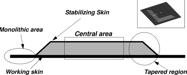
Three different areas can be found in an asymmetric sandwich plate (see figure 1). The central area is a pure asymmetric sandwich region and is made of a first thick laminated skin known as "working skin". The working skin takes most of the membrane stresses carried by the sandwich. The stability of the working skin under compressive or in-plane shear loads is ensured by a Nomex honeycomb core and a thin skin called "stabilizing skin" made with one or two layers of carbon or Kevlar. The junction area is made of monolithic carbon composite and the loads are transferred to the central sandwich via a tapered region. Designing bolted junctions in a monolithic composite increases the load-carrying capacity and computational methods like the point-stress method provide reliable results. This sandwich is intrinsically non-symmetrical and the stabilizing skin always remains thin. As a consequence, this technol-ogy is not able to carry important flexural moments or lateral pressures but only in-plane loads. Therefore, it may be applied only to the design of helicopters or passenger aircraft with non pressurized fuselages.
Many researchers have paid attention to sandwich structures (Noor [7]). However, only a very few studies deal with the complete geometric configuration including the tapered transi-tion zone or with asymmetric sandwiches subjected to in-plane loads. Frostig’s theory [8] is based upon 3D elasticity for the antiplane core and Kirchhoff’s hypothesis for the skin. The through-the-thickness displacement field is found nonlinear which enables a description of the
linear variation of the compression stresses and the constant shear stresses in the thickness of the core. Recently, Kuczma [9] conducted an experimental and numerical study on tapered symmetric beams with foam core. Both the failure mode and the numerical study showed that stress concentration occurs at the root of the taper and causes damage initiation. Chai et Al [10] propose a sandwich beam model with a classical theory to describe the central region and a two bar model to describe the tapered transition region. A good comparison with experiments under tension is achieved and stress and strain fields along the whole skin can be studied. Chai et Al [10] point out the main limitation of their models which is the linear hypothesis. Chai et Al [10] concluded that linear analysis of such tapered sandwich structures is inadequate. A simple analytical model with only 4 unknowns after a changing of unknowns showed clearly that the structural behavior of asymmetric or symmetric sandwich structures loaded in com-pression by only one of the two skins is geometrically nonlinear (Castanié et al [11]). Never-theless, the linear analysis remains available for the lower loads.
This paper presents a specific geometrically nonlinear theory of asymmetric sandwich plates. Another objective is to provide a user-friendly and computationally cost-effective tool for composite design offices. Quicker design loops in the pre-project phase will become possi-ble and cost savings are expected. In order to meet these requirements, the theory was devel-oped to obtain the best compromise between quality of mechanical description and minimum mathematical complexity. The efficiency of the theory will then be demonstrated, first by com-parison to numerical models and second by correlating original structural tests on plate speci-mens provided by Eurocopter France.
2-Theoretical analysis.
2.1 Modeling strategy and general hypothesis.
The four-sided taper region and non-uniform thickness of the skin (resulting from the technology of the junctions) creates a shape too complex for a nonlinear study under the requirements presented above. As a consequence, only the parallelepipedic shape of the purely asymmetric central region must be considered and to represent globally the load introduction via the taper-region, two parameters δ and N% are introduced (see Figure 2). First, δ (mm)
rep-resents the shift between the middle plane of the monolithic region and the middle plane of the working skin which occurs as a result the computation of bolted junctions. Second, N (%) rep-resents a small percentage of the compressive or shear load F which may be taken directly by the stabilizing skin. This percentage may be caused by the flow of loading across the upper skin of the tapered region.
The laminates of the two skins are assumed to be orthotropic equivalents. Because the core is a Nomex honeycomb, the classical hypothesis of antiplane core is assumed and the core will be able to carry only transverse shear or compression.
Static tests on the specimens under compression showed that the maximum deflection remains under 15% of the length and that the ultimate compressive strain to failure can reach 1.5%. Therefore, a total Lagrangian formulation in the case of low rotation and strains seems to be appropriate.
2.2 Kinematic fields.
As with most authors, a displacement method is used. First Order Shear Theory (Mindlin [12], Minguet et al [13]) or Higher Order Shear Theory (Manjunatha [14]) are efficient for composite laminate analysis and can be used with accuracy to obtain the global response of complexly-shaped sandwich structure by the finite element method. Nevertheless, because a distinction must be made between the structural behavior of the working skin and the
stabiliz-ing skin (Castanié et al [11]), a Zig-Zag kinematic field is preferred. Moreover, this kinematic field seems to be more accurate for nonlinear analysis (Ferreira et al [15]).
As the working skin may be relatively thick and may take flexural moments induced by the shift δ, a Kirchhoff’s assumption is made. Unlike the working skin, the stabilizing skin remains permanently thin and is only loaded by core shear or by direct loading (parameter N) through its midplane. So a membrane modeling may be sufficient. A basic beam model using only four unknowns was also developed and demonstrates globally the relevancy of such assumptions (Castanié et al [11]).
When core compression is taken into account, it may generate coupling terms and increases the mathematical complexity (Castanié [16]). In order to minimize this phenomenon, the first unknown kinematic field will be the displacements of middle plane points of working skin (u0, v0, w0) as usual and the second the displacement of core/stabilizing skin interface points (u2, v2, w2) (see figure 3) (Ojalvo [17], Xavier et al [18]). The subscript 0 refers to the quantities of the working skin middle plane and subscripts 1, c and 2 to the quantities of the
working skin, the core and the stabilizing skin respectively. According to the above assump-tions, the working skin displacements are written:
u1(x,y,z) = u0(x,y) - z . ; v1(x,y,z) = v0(x,y) - z . ; w1(x,y,z) = w0(x,y) (1) And for the stabilizing skin, it follows:
u2(x,y,z) = u2(x,y) ; v2(x,y,z) = v2(x,y) ; w2(x,y,z) = w2(x,y) (2) The core displacements are linearly interpolated through the thickness and result in the following: (3) (4) x ∂ ∂w0 y ∂ ∂w0 uc(x y z, , ) 1 hc --- z h1 2 ---– u 2 z h1 2 --- +hc – u 0 ⋅ – ⋅ h1 2 --- z h1 2 ---+hc – x ∂ ∂w0 ⋅ ⋅ + ⋅ = vc(x y z, , ) 1 hc --- z h1 2 ---– v 2 z h1 2 ---+hc – v 0 ⋅ – ⋅ h1 2 --- z h1 2 ---+hc – y ∂ ∂w0 ⋅ ⋅ + ⋅ =
(5)
The linear interpolated core thickness displacements are consistent with the constant transverse core shear stress induced by the antiplane core hypothesis. However, they are not consistent with the linear variation of the transverse compression core stress. Hence, this kine-matic field can only provide an average of the core transverse compression stress. Applying Von Karman strains formulas, the working skin strains become:
;
(6) The same can be obtained for the stabilizing skin apart from the flexural terms. It appears that . Thus, the core shear strains can be expressed more simply as:
(7)
(8) The tranverse core compression strain εzz is:
(9) 2.3 Kinematic unknown field discretization.
The working skin deflection function is:
(10)
In the above, and are non-dimensional coordinates ( and ), Akl are the unknown polynomial coefficients and CLi from 1 to 4 are exponents.
wc(x y z, , ) z h1 2 ---– hc ---⋅[w2–w0]+w0 = ε1 xx ∂x ∂u0 z x2 2 ∂ ∂ w0 ⋅ 1 2 ---x ∂ ∂w0 2 ⋅ + – = εyy1 y ∂ ∂v0 z y2 2 ∂ ∂ w0 ⋅ 1 2 ---y ∂ ∂w0 2 ⋅ + – = γ1xy y ∂ ∂u0 x ∂ ∂v0 z x∂y 2 ∂ ∂ w0 ⋅ x ∂ ∂w0 y ∂ ∂w0 ⋅ + – + = w2–w0«u2–u0 γxzc (u2–u0) hc --- 1 hc ---+ z h1 2 ---– x ∂ ∂w2 ⋅ (z–(h1+hc)) x ∂ ∂w0 ⋅ – ⋅ = γyzc (v2–v0) hc --- 1 hc ---+ z h1 2 ---– y ∂ ∂w2 ⋅ (z–(h1+hc)) y ∂ ∂w0 ⋅ – ⋅ = εzzc w2–w0 hc ---= w0(ξ η, ) Akl l=0 Mw
∑
k=0 Mw∑
ξk ηl 1+ξ ( )CL1 1–ξ ( )CL2 1+η ( )CL3 1–η ( )CL4 ⋅ ⋅ ⋅ ⋅ ⋅ ⋅ = ξ η ξ = 2 x⋅ ⁄L η = 2 y⋅ ⁄bThe use of non-dimensional coordinates makes the unknown polynomial coefficients homoge-neous and avoids working with excessively small or large numbers which cause numerical problems such as matrix conditioning.
Trigonometric series are generally preferred for solving laminate problems (Brown [19]). Nevertheless, our experience shows that this polynomial series offers adequate numeri-cal performance since Mw remains low. Moreover, this series satisfies the usual free, simply-supported or clamped boundary conditions by simply setting CLi respectively to 0, 1 or 2. The stabilizing-skin deflection function takes the same form with the same exponents CLi and the
same Mw number. Membrane displacements are discretized using the basic polynomial basis
. The solution of the elasticity problem includes a rigid body displacement, so 6 degree of freedom must be eliminated in order to obtain the pure elasticity solution. The out-of-plane displacements are eliminated by imposing at least a two side simply-supported boundary con-dition (e.g. CL1=CL2=1), and the three remaining membrane displacements are eliminated as follows: the origin O displacements and the rotation around O are set equal to zero. In so doing, the plate can freely take in-plane biaxial compression as well as shear. The following conditions arise:
(11) And the polynomial series of the working skin membrane displacement can be written:
(12)
(13)
No particular conditions have to be set in the case of the stabilizing skin, so one obtains: ξk⋅ηl u0(0 0, ) = 0 v0(0 0, ) = 0 η ∂∂ u0(0 0, ) = 0 u0(ξ η, ) Bk0⋅ξk k=1 Mu
∑
+η Bk1⋅ξk k=1 Mu∑
⋅ Bkl⋅ηl l=2 Mu∑
k=0 Mu∑
+ ⋅ξk = v0(ξ η, ) C0l⋅ηl l=1 Mv∑
Ckl l=0 Mv∑
k=1 Mv∑
+ ⋅ ⋅ηl ξk =and (14)
The degrees Mu and Mv of the above functions are linked with the degree of the function w0(x,y) due to compatibility of membrane/deflection displacements induced by the nonlinear Von Karman strains. It is seen in equation (10) that this degree is the sum of Mw and the CLi exponents. Thus, the total number of unknowns of the problem depends upon the deflection exponent Mw, but also upon the boundary conditions via the CLi exponents. To illustrate this unusual property, 53 unknown coefficients of polynomials are found in the case of a two side simply-supported problem (CL1 =CL2 =1 and CL3 =CL4 =0) with Mw=1, but a four side clamped problem (CL1 =CL2 =CL3 =CL4 =2) with Mw=4 requires 1071 unknown coefficients of polynomials. Hence, one can note that the computing cost becomes heavily dependent on the boundary case.
2.4 Matrix formulation.
The solving method is based upon the nonlinear finite element method (Bathe [20], Cris-field [21]) which is generalized by substituting nodal displacement by unknown polynomial coefficients which become generalized coordinates. Thus, a matrix formulation must be used. The notation and conventions used come from these two references. For the displacement field w0, equation (10) can be rewritten to obtain:
(15)
where the following function is defined:
; α,β,γ are integers. (16) The unknown coefficients Akl of the polynomial are stored in the vector of the generalized coordinates : u2(ξ η, ) Ekl⋅ηl l=0 Mu
∑
k=0 Mu∑
⋅ξk = v2(ξ η, ) Fkl l=0 Mv∑
k=0 Mv∑
⋅ ⋅ηl ξk = w0(ξ η, ) Akl l=0 Mw∑
k=0 Mw∑
ϕξk CL 1 CL2 , , ϕl CL, 3,CL4 η ⋅ ⋅ = ϕ α β γ, , x xα⋅(1+x)β⋅(1–x)γ = w0(ξ η, ) w0(17) The change from two indices k and l to one index only p is bijective. The expression of the interpolation vector of the displacement , is :
(18)
The displacement can now be rewritten as:
(19) By then following the same procedure for the other displacements, the vectors of the generalized coordinates u0, u2, v0, v2, w2 can be defined, as well as the corresponding
interpola-tion vectors . For the first derivatives of the displacements one defines
interpolation vectors of type b which are expressed with the aid of the function and its
first derivatives, e.g. :
(20) with :
(21)
For the curvature terms, one sets :
; ; (22)
The expression of the c vectors is obtained from second and first derivatives of
by identification, as for expression (21). From equation (6), the strains in the working skin can be expressed as: w T 0 = {A00, ,… A0Mw,A10, ,… Akl, , ,… … AMwMw} = {… …, ,w0p,… …, } w0(ξ η, ) Thw 0 h T w0 ϕ0 CL 1CL2 , , ξ ϕ 0 CL, 3,CL4 η ⋅ … ϕk CL 1CL2 , , ξ ϕ l CL, 3,CL4 η ⋅ … ϕ Mw,CL1,CL2 ξ ϕ Mw,CL3,CL4 η ⋅ , , , , = w0(ξ η, ) w0(ξ η, ) Thw 0⋅w0 = hu 0,hv0,hu2,hv2,hw2 ϕ α β γ, , x x ∂ ∂w0 b T w0,x⋅w0 = b T w0,x 2 L ---- ϕ′ 0 CL, 1,CL2 ξ ϕ 0 CL, 3,CL4 η ⋅ … ϕ′ k CL, 1,CL2 ξ ϕ l CL, 3,CL4 η ⋅ … ϕ′ Mw,CL1,CL2 ξ ϕ Mw,CL3,CL4 η ⋅ , , , , ⋅ = x2 2 ∂ ∂w0 c T x⋅w0 = y2 2 ∂ ∂w0 c T y⋅w0 = x∂y 2 ∂ ∂w0 c T xy⋅w0 = ϕ α β γ, , x
with (23) in which one can distinguish the membrane term , the curvature term and the
nonlinear term . With the notations already introduced, the membrane terms can thus be written:
(24)
The same identification procedure can be carried out for the strains in the stabilizing skin and the core. Only the nonlinear term needs to be treated differently (Crisfield [21], section 8.1):
with (25)
2.5 Solution of the problem.
The equilibrium of the structure is found after writing the virtual work principle (Cris-field [21], section 1.3.2 or 2.1):
δUd - δWFext = 0 (26)
δUd is the strain energy of the structure under the virtual displacement δp and δWFext is
the external virtual work. In the case of a total Lagrangian formulation and with no body force, equation (26) can be written:
(27) ε1 { } { }εm1 z⋅{ }χm1 {εnl1 } + + = T{ }ε1 = {ε1xx,ε1yy,γ1xy } ε1m { } χ m 1 { } εnl1 { } ε1m { } x ∂ ∂u0 y ∂ ∂v0 y ∂ ∂u0 x ∂ ∂v0 + b T u0,x 0 0 Tbv 0,y b T u0,y b T v0,x u0 v0 ⋅ B m0 pm 0 { } ⋅ = = = εnl1 { } 1 2 ---∂w0 ∂x --- 0 0 ∂w0 ∂y ---∂w0 ∂y --- ∂w0 ∂x ---∂w0 ∂x ---∂w0 ∂y ---1 2 --- T0 Bs 0 {w0} ⋅ ⋅ ⋅ = ⋅ ⋅ = b T w0,x b T w0,y Bs 0 = Tr PK([ 2] δ⋅[ E]) V0
∫
dV0 F⋅δp ∂V0∫
dS0 =where [PK2] is the second Piola-Kirchhoff stress tensor and [δE] is the Green’s strain
tensor. Setting a Newton-Raphson incremental/iterative procedure requires the computation of the tangent stiffness matrix [KT] (Bathe [20], Crisfield [21]) which relates the generalized coordinates increment ∆p to the external forces vector increment ∆qe:
(28) Computing [KT] for our asymmetric sandwich gives a set of 81 submatrices before the assemblage process. One example is given here of the practical method of calculating one of these submatrices. The membrane terms for the working skin are chosen for this example. Full detail of the computation may be found in (Castanié [16]). The expression of the strain energy of the working skin after integration through the thickness is:
(29) The stress resultants in (29) are:
and (30)
in which is the material property matrix (orthotropic) of the laminate making up the working skin. Equation (24) gives:
(31) The membrane part of the internal force vector (Crisfield [21], section 8.1.4) is then writ-ten after identification in (29):
(32) The expression of the tangent stiffness matrix for the working skin is of the form:
(33)
The tangent stiffness submatrices are obtained by differentiation of the corresponding ∆p = [ ]KT –1⋅∆qe δU1d=
∫
∫
TN1⋅({δε1m}+{δεnl1 })dA1+∫
∫
TM1⋅{δχm1}dA1 N1 = h1⋅[QPT]⋅({ }ε1m +{εnl1 }) M1 = h31 ⁄12⋅[QPT]⋅{ }χm1 QPT [ ] δε1m { } B m0 δpm 0 { } ⋅ = q T i m, 0 N T 1⋅ Bm0∫
∫
dA1 = KT1 [ ] Km0m0 1 Km 0w0 1 Km 0w0 1 Kw 0w0 1 =internal force subvectors:
(34) After identification, with the aid of relations (29), (30) and (32), (34) gives:
(35) Matrix can also be broken down into:
(36)
From the expression of provided in equation (24), the developed calculation
leads to:
(37) It can be demonstrated that each term (p,q) of the submatrice
takes the form:
(38) There is a bijective relationship between p and (k1,l1) and q and (k2,l2). At this stage, the choice of the polynomial functions (10), (12), (13), (14) enables the variables to be separated. Using the properties of the function results in:
(39)
Solving the problem requires the calculation of the integral of the function and
of its first and second derivatives. Indeed this calculations is simple with the help of the fol-lowing relationships: δqi m 0 , h1 Bm0 T QPT [ ] δ B m0 ⋅{pm0} 1 2 ---⋅ T0 ⋅ Bs0 ⋅{w0} + ⋅ ⋅
∫
∫
dA1 ⋅ = Km 0m0 1 [ ] h1 B m0 T QPT [ ] B m0 ⋅ ⋅∫
∫
dA1 ⋅ = Km 0m0 1 [ ] Km 0m0 1 [ ] Ku0u0 1 Ku 0v0 1 Ku 0v0 1 Kv 0w0 1 = Bm 0 Ku 0u0 1 [ ] h1 Q11 PT bu 0,x b T u0,x ⋅ [ ] 1∫
∫
dA1 ⋅ ⋅ h1 Q33 PT bu 0,y b T u0,y ⋅ [ ] 1∫
∫
dA1 ⋅ ⋅ + = SM1 [ ] bu 0,x b T u0,x ⋅ [ ] 1∫
∫
= dA1 SM1 [ ]p q, b L --- ϕ′ k1, ,0 0 ξ ϕ l1, ,0 0 η ϕ′ k2, ,0 0 ξ ϕ l2, ,0 0 η ⋅ ⋅ ⋅ dξ 1 – 1∫
1 – 1∫
dη ⋅ = ϕ α β γ, , x SM1 [ ]p q, b L --- ϕ′ k1, ,0 0 ξ ϕ′ k2, ,0 0 ξ ⋅ dξ 1 – 1∫
ϕ l1+l2, ,0 0 η η d 1 – 1∫
⋅ ⋅ = ϕ α β γ, , x(40)
and (41)
Relationship (41) shows that the integral of the derivatives of is a linear combi-nation of equation (40). From a practical point of view, the integrals are computed separately and stored in a three-dimensional matrix, thus enabling to gain an order of magnitude in C.P.U. cost.
The expression of the nonlinear terms is obviously more complex, but the method of cal-culation is identical and is also based in fine on equation (40) (Castanié [16], appendix 5). A Fortran program was written which offers the choice of Mw from 1 to 4 and of the different boundary conditions on the four sides. A comparison will now be made with finite element models to validate the theoretical and computer developments.
3-Comparison with Finite Element Models.
The FEA software SAMCEF (by SAMTECH Group S.A.) is used. Several different ways exist to modelize sandwich structures but the most accurate one requires 3-dimensional elements. Two 3-dimensional shell elements are taken in the thickness of the working skin. Therefore, the sandwich will be loaded through the nodes of the midplane of the working skin. Only one dimensional shell element is taken in the stabilizing skin thickness and one 3-dimensional element in the core thickness. This paper will present only two significant loading cases. First, a comparison with a 200 x 200 mm plate under compression will be achieved. Sec-ond, a 800 x 800 mm shear plate will be studied. In the case of shear loads, the geometrically nonlinear behavior is less sensitive. Hence, to perform a more accurate nonlinear analysis and
xα⋅(1+x)β⋅(1–x)γ 1 – 1
∫
dx β β! i – ( )! i!⋅ --- γ! γ–j ( )! j!⋅ --- ( )–1 j i+ +j α+1 --- (1–( )–1 i+ +j α+1) ⋅ ⋅ ⋅ j=0 γ∑
i=0 β∑
= ϕ′α β γx, , α ϕ⋅ αx –1, ,β γ–β ϕ⋅ α βx, –1,γ+γ ϕ⋅ α β γx, , –1 = ϕ α β γ, , xincrease the deflection, the plate size is larger so its stiffness is lower. Both plates are simply-supported and 10 elements per side are used in the compression case, 20 in the shear one. For both cases, Mw=2. This value provides the best balance between computing time cost and accurate results (Castanié [16]). A Newton-Raphson method is applied with a convergence limit specified as 10-3 for the compression case. For the shear case, the deflection behavior is strongly nonlinear and requires the use of a convergence criterion of 10-5 which is more accu-rate.
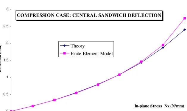
Figure 4 shows the nonlinear deflection at the center of the sandwich versus the in-plane stress Nx. If the maximum error of 11% is reached at the last increment, the error remains lower than 1% during the first half of the loading.
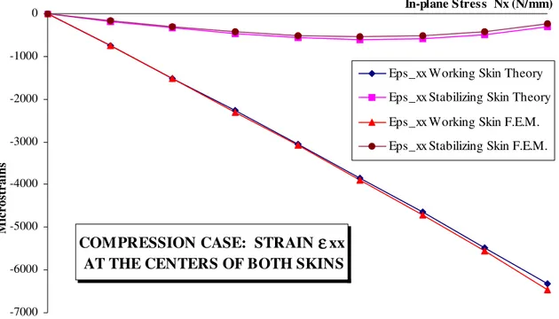
In figure 5, the main structural response curves (strains at the center of the two skins ver-sus Nx) of asymmetric sandwich structures are shown. The response of the working skin is found to be nearly linear and theoretical and numerical results are very close. The maximum difference is not more than 1.9%. The structural load-strain response of the stabilizing skin is mainly induced by the non-linear effects. Due to the asymmetry and the loading via the work-ing skin, there is a shift between the neutral plane of the sandwich and the loadwork-ing plane. So that introducing a compression force also means introducing a local bending moment. It appears that this moment is linked to the deflection of the sandwich beam. So, there is a cou-pling effect between the deformed state of the sandwich and the loading, and the behavior of the stabilizing skin becomes geometrically non-linear (Castanié [11]). For the stabilizing skin too, the difference between the numerical and theoretical results remains low.
The average of the core compression stress versus Nx is studied in Figure 6. The theoret-ical results are compared to the average value given by the element located at the center of the sandwich. The curves are similar, so the theory can provide this value with acceptable preci-sion.
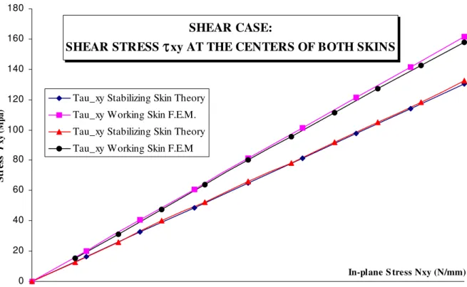
For the shear case, the deflection and the shear stresses at the centers of the skins are shown in figures 7 and 8. The numerical and theoretical value of the shear stresses τxy are very close. The difference is not more than 1.3% for the working skin and 2% for the stabilizing skin. One will notice the linearity of the response. For the shear case deflection, the theory pro-vides satisfactory results. The maximum difference is 25% at the last increment. It seems that the shape functions may not be able to describe the more complex shear deformed state. How-ever, a test with Mw = 4 has not provided any significant improvements. Besides, only for the case of shear deflection the theoretical results are sensitive to the convergence criteria. For a given criteria of 10-3, the center deflection at the last increment is 0.687 mm, although for a given criteria of 10-5 the value is 0.748 mm. The difference reaches 8%.
In the case of main stresses or strains, the differences between the 3-dimensional finite element model and the theory remain lower than 1 or 2 %. The nonlinearity sensitive quantities or low energy values such the shear deflection or the stabilizing skin strains are approached with an increasing error (from 10 to 25 % at the last increment). This error may be induced by too rigid polynomial functions or by a lack of accuracy in the finite element discretization. Nevertheless, an important safety margin (more than 2) must be taken with the static computa-tion results according to the reduccomputa-tion in the residual strength after impact. Therefore, the non-linear calculation can provide only the ultimate strength of the structure. Using Mw= 2, even with a relative lack of precision on a small number of quantities, provides accurate enough results for the design of current structures in the pre-project phase.
As a conclusion, for both the quality of the calculation and the computing cost, the the-ory satisfies the industrial requirements. The results are obtained within a minute on a personal computer unlike the hour for F.E.M. Most of the computing time is due to the calculation of the nonlinear tangent stiffness submatrices and it increases nonlinearly with the number of unknowns. The material and kinetic hypothesis done for the skins and the core are efficient for
the modeling of asymmetric sandwich structures.
4- Experimental Study.
4.1 Combined compression/shear testing concept.
European airworthiness certification of composite structures is based on a multi-scale and pragmatic testing approach known as "pyramid of tests" (Rouchon [22]). Classical mate-rial tests on elementary coupons make the basis of the pyramid and full-scale testing the top. The successive stages of the pyramid represent the progressive design complexity, allowing the step by step validation of the models used in structural calculations. Similar approaches have been used in the U.S.A. (Liu [23]) or in the former U.S.S.R. (Zagainov [24]). So, interme-diate tests on non-specific aircraft plate specimens can be used to validate a new technology such as asymmetric sandwich structures. Classically, compression/traction tests are conducted with a universal testing machine (Minguet et al [13]) and shear tests with the help of picture frames (Fairlay [25]). However, since the boundary conditions and/or junctions technology of these tests differ from those of the aircraft, the extension of the experimental strength to the aircraft structure reality cannot be very accurate, especially in the case of composite structures. Besides, one cannot obtain the important practical case of combined shear/compression load-ing with such classical tests even with off-axis tests. A small number of specific testload-ing machines do exist most often built by aeronautic testing centers or manufacturers (for example: Klein [26], Peters [27]).
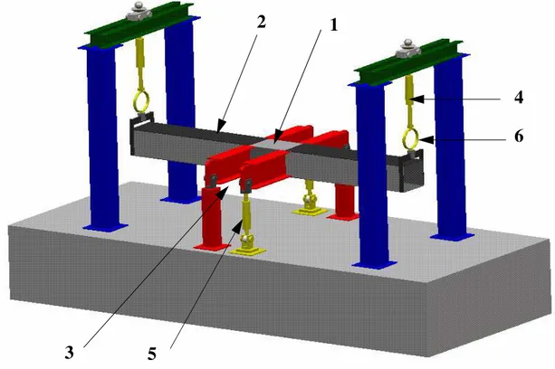
The proposed concept tries to be similar to a helicopter tail boom. So, it takes on the same overall shape (a box) and the same loading (bending/torsion). The complete test rig is shown in figure 9. The representative asymmetric sandwich test plate (1) (see also fig 1 and 2) is bolted to the central part of the test rig. The test rig is composed of one longitudinal box (2) made of aluminum alloy and two crossing steel I-beams (3). When the longitudinal box is
loaded with the hydraulic actuators (4) at its two end points, the box is then subjected to four point bending and the test plate takes compression or in-plane traction stresses. When the I-beams are loaded with the hydraulic actuators (5), a torque is generated in the central part of the box and the test sample takes in-plane shear stresses. If these two loadings are carried out simultaneously, the test plate is subjected to in-plane combined stresses. The actuators are acti-vated by manually operated pumps. The increase of loading is incremental. This technique allows work to be carried out with an imposed displacement in order to stop the test at the first sign of failure. Following this, the failure patterns obtained can be analyzed. Some design solu-tions and complementary test results on impacted plates can be found in (Castanié [16],[28]).
Such structural tests provide hard data. Extrapolating the test strengths to real structures is more reliable and less conservative than classical tests. However, it implies further complex-ities. To be conducted, the experiment requires extensive know-how and some difficulties arise while finding the real loading of the specimen (Klein [26]). Besides, the central box element has to be replaced frequently.
4.2 Test results.
Six tests on representative plates provided by Eurocopter were carried out, two under pure compression, 2 under pure shear, 2 under combined shear /compression. The specimens comprise a peripheral zone of 350 x 250 mm due to bolted fixing and a central zone of 200 x 200mm representing the pure asymmetric sandwich including the taper-region.
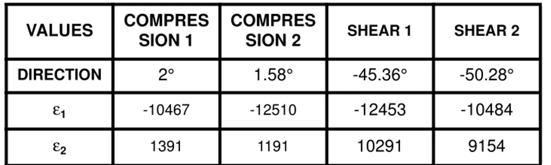
Two three-strain-gauge-rosettes were systematically stuck at the center of the skins. The ultimate strain, obtained at the last increment of force before the specimen failure, main direc-tions and failure modes are shown in tables 1 and 2. The failure patterns are drawn in figures 10 and 11.
Apart from the first shear test, all the specimens were broken following the static failure of the working skin (Castanié [16],[28]). No global buckling was observed and this is mainly
the consequence of the small size of the specimen, the all-clamped boundary conditions and the monolithic and taper-region technology of Eurocopter. The main direction ultimate com-pressive strain to failure is always higher than -10000 microstrains. This value is remarkably high, unexpected in structural testing and close to the values obtained while testing simple ply materials. Firstly, it demonstrates the real structural efficiency of asymmetric sandwich struc-tures and secondly, it globally validates the concept to carry out failure static tests. Besides, results are obtained under complex loading with main strain directions of 28° and 60°, which demonstrates the capability of the testing solution to carry out shear/compression investiga-tions.
4.3 Tests/theory comparisons.
The main advantage of the concept (a good similarity with aeronautical structures) leads to the main disavantage, which is a real difficulty in finding the real loading of the specimen due to structural redundancy. However Klein [26] overcomes this difficulty by sticking about 150 strain gauges on a one-meter size specimen. In our tests, more problems arise because of the small size of the test plate and the local plastic behavior of the central box induced by the high strain rate (>1%) of the carbon specimens. This accepted local plastic behavior is the key-condition for breaking carbon without breaking the whole testing rig.
Therefore, only an in-situ measurement of the specimen local in-plane loads seems to be realistic. A particular structural property of the asymmetric sandwich structure is the high sen-sitivity of the stabilizing skin’s nonlinear response to the global loading of the whole sandwich (Castanié [11]). According to this property, an original method will be used to correlate the tests. The local load is measured in-situ at the center of the working skin with a rosette and a comparison with the theory is achieved at the center of the stabilizing skin. This method avoids the use of a material and geometrically nonlinear finite element model of the whole box and the specimen.
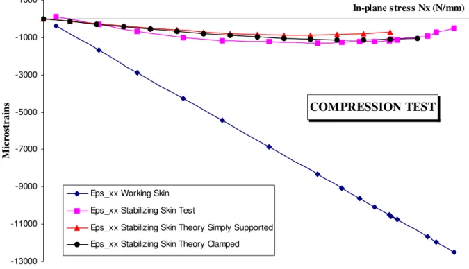
The comparison of the theory and test in the second compression test is shown in figure 12. The calculated and measured strains
ε
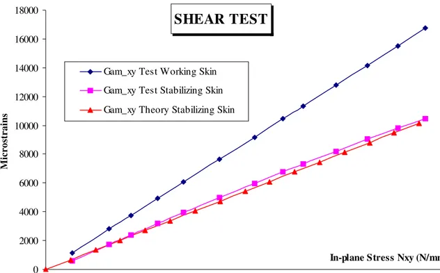
xxPS at the center of the stabilizing skin are close for N = 3% and all edges clamped. Nevertheless, the shapes of the curves are not exactly the same, unlike the case of tests performed on asymmetric sandwich beams (Castanié [16]). In such a complex testing machine and specimen, Saint-Venant influence is present and the theory is not able, at the moment, to deal with the rigidity induced by the corners of the taper-region for example.For the shear case, the method of comparison is the same but a correction coefficient must be used. In fact, only a ratio of the in-plane shear load is measured by the working skin rosette and this ratio depends on the plate size. One must remember that only the working skin is effectively shear loaded. For the lower sizes, theoretical simulations show that only the working skin carries shear loads, so the asymmetry is complete. For larger sizes, shear loads are carried by both skins, and when the size is large enough, the strains are identical in the two skins and the ratio of stresses between the two skins is the ratio of shear rigidity. So, for the larger sizes, there is no asymmetric effect and the sandwich behaves like a classical symmetric sandwich structure.
The ratios of the shear strains γxy SKINS/γxy REFERENCEfor both skins versus the plate size (square plate L = b) are drawn in figure 13. The reference strain is the strain computed when the plate size is very small (100% of the in-plane shear load is taken by the working skin). As a consequence, in the case of our specimen of size 200 x 200 mm, the shear load measured at the center of the working skin is only 69% of the total load taken. After computing the real in-plane shear load taken by the whole sandwich, a good comparison test/theory is achieved
(fig-ure 14).
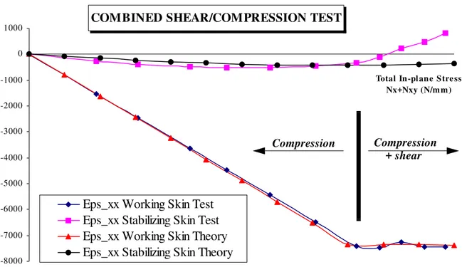
During the test under combined loading, the compression is first applied until the strain at the center of the working skin reaches -7500 microstrains. Then, the shear load is applied
until failure of the specimen. Both methods used in the above tests are used to correlate the combined test. The compressive phase is well correlated (figure 15) which also validates the methodology proposed. For the shear phase, the theoretical results are again in accordance with the test (figure 16). A non-uniform compressive strain during the torsion loading phase is found experimentally (figure 15). A coupling effect between torsion and bending actuators arises due to the rotation during the torsion loading of the fixing points of the bending actua-tors. So manual adjustments of the pressure must be done.
As a conclusion, despite the complexity of the testing equipment and the relative sim-plicity of the theory, it is still possible to make an efficient comparison since the in-plane loads are measured in-situ on the working skin and the stabilizing skin’s structural properties are used. However, many problems are due to the small size of the test specimen and a new design should use a plate at least twice as large which would minimize Saint-Venant’s effects.
5-Conclusions.
A geometrically nonlinear theory of asymmetric sandwich structures based upon classic displacement assumptions was developed. Kirchhoff’s hypothesis is made for the working skin and the stabilizing skin is of membrane type. The in-plane rigidities are neglected in the core but not the transverse shear and compression. A total Lagrangian formulation in the case of low rotations and strains is used. The theory was validated by comparison with 3-dimensional finite element models, beam tests (Castanié [16]) and complex structural plate tests.
The industrial requirements are fulfilled in that acceptable precision and results are obtained within the minute on personal computers. This low-cost CPU time theory should make it possible to perform Monte-Carlo analyses of manufacturing dispersions in composite structures or structural optimization. Moreover, extending the theory to bending is easy and symmetric sandwiches are a particular case of asymmetric sandwiches, therefore, the theory
should be used as a general tool for the computation of sandwich structures with soft cores (Castanié [16]).
The original structural tests performed on Eurocopter technology asymmetric sandwich plates demonstrate the high structural performance of this technology. The ultimate compres-sive strains to failure are close to material values and always greater than one per cent. More-over, tests have been conducted under complex shear/compression loading providing results for main directions at 28° and 60°.
Asymmetric sandwich structures appear to offer a real opportunity for the design of lightweight structures due to their high specific strength. The weight fraction (structure to total weight) of a complete helicopter structure may be under 10 per cent. However, improvements must still be made on the design of the taper-region and on impacted plate behavior. The next step of research must now be made in this direction.
6-Bibliography.
1. Amstrong K.B.,Stevens D.W., Alet J. 25-years of use for Nomex honeycomb in floor panels and sandwich structures. In: 50 years of advanced materials or back to the future, 15th International Euro-pean Chapter Conference of the SAMPE, Toulouse 1994, pp 17-39.
2. Hooper E. H. Starship: a model for future design. Materiaux et Techniques, Juin 1989, pp 23-30. 3. Sheahen P., Bersuch L., Holcombe T., Baron B.: Robust Composite Sandwich Structures. AIAA Paper n° A98-25225/ AIAA 98-1873.
4. Abrate S. Localized impact on sandwich structure with laminated facings. Appl Mech Rev 1997; 50(2): 69-82.
5. Thomsen O. T. Sandwich plates with ’through-the-thickness’ and ’fully potted’ inserts : evaluation of differences in structural performance. Compos Struct 1995; 40(2):159-174.
6. Zenkert D. The handbook of sandwich construction. EMAS Publishing 1997.
7. Noor Ahmed K., Burton Scott W., Bert C. W. Computational models for sandwich panels and shells. Appl Mech Rev 1996; 9: 155-199.
8. Frostig Y., Peled D. High-order bending of piecewise uniform sandwich beams with a tapered transi-tion zone and a transversely flexible core. Compos Struct 1995; 31: 151-162.
9. Kuczma S. C., Vizzini A. J. Failure of sandwich to laminate sandwich structures. AIAA Journal 1999; 37(2): 227-231.
10. Chai G.B., Chuwa L.S. Stress distribution in sandwich beams under tension. Compos Struct 1999; 45(3): 195-204.
11. Castanié B., Barrau J.J., Jaouen J.P. Structural analysis of asymmetric sandwich beams with com-pressible core. In: Proceedings of the Fifth International Conference on Sandwich Construction, 443-452, Zurich, 5-7 September 2000. EMAS Publishing.
12. Mindlin R.: Influence of rotatory inertia and shear on flexural motions of isotropic elastic plates. Trans ASME 1951; 73:31-38.
13. Minguet P., Dugundji J., Lagace P. A. Postbuckling behavior of laminated plates using a direct energy-minimization technique. AIAA Journal 1989: 27(12): 1785-92.
14. Manjunatha B.s., Kant T. New theories for symmetric/unsymmetric composite and sandwich beams with C0 finite elements. Compos Struct 1993; 23: 293-312.
15. Ferreira A.M., Torres-Marques A., Cesar de Sa J.c. Comparison of three shear-deformation theories in the non-linear analysis of sandwich shell elements. In: Proceedings of the Euromech 360 Collo-quium, "Mechanics of sandwich structures", Saint-Etienne 13-15 May 1997. Kluwer Academic
Pub-lishing.
16. Castanié B. Contribution à l’étude des structures sandwichs dissymétriques, Thesis of the Ecole Nationale Supérieure de l’Aéronautique et de l’Espace, Toulouse 2000 (in french). http:// www.supaero.fr/disque2/001130.pdf
17. Ojalvo I.U. Departure from classical beam theory in laminated, sandwich and short beams. AIAA Journal 1977; 15(10): 1518-1521.
18. Xavier P. B., Chew C. H., Lee K. H. Static response of unsymmetric sandwich beams using an improved zig-zag model. Compos Eng 1993; 3 (3): 235-248.
19. Brown R.E., Stone M.A. On the use of polynomial series with the Rayleigh-Ritz method. Compos Struct 1997; 39(3-4): 191-196.
20. Bathe K.-J. Finite element procedures in engineering analysis. Prentice-Hall 1982. 21. Crisfield M.A. Non linear finite element analysis of solids and structures. Wiley 1991.
22. Rouchon J. Certification of large airplane composite structures, recent progress and new trends in compliance philosophy. 17th ICAS Congress, Stockholm 1990.
23. Niu M.C. Y. Composite Airframe Structures. Hong-Kong Conmilit Press LTD 1992.
24. Zagainov G.I., Lozino-Lozinsky G.E. : Composite Materials in Aerospace Design. Chapman et Hall Ed 1996.
25. Farlay G. L., Baker D.J. In plane shear test of thin panels. Exp Mech 1983; March: 81-88. 26. Klein H. General about buckling tests with thin-walled shells. Rapport DLR- Mitt; 89-13.
27. Peters R. W. Buckling tests of flat rectangular plates under combined shear and longitudinal com-pression. NACA Technical Note No1750. (1948)
28. Castanié B., Barrau J.J., Crézé S., Jaouen J.P. Experimental analysis of asymmetric sandwich plates under compression, shear and combined loading. In: Proceedings of the Fourth International Confer-ence on Sandwich Construction, 659-670, Stockholm, 9-11 June 1998. EMAS Publishing.
TABLES.
Table N° 1: Main shear and compressive strains at the center of the working skin before failure (units: microstrains).
Table N° 2: Main combined compression/shear strains at the center of the working skin before failure (units: microstrains) and compressive values in the 0° and 45° ply directions.
VALUES COMPRES
SION 1
COMPRES
SION 2 SHEAR 1 SHEAR 2
DIRECTION 2° 1.58° -45.36° -50.28°
ε1 -10467 -12510 -12453 -10484
ε2 1391 1191 10291 9154
VALUES COMBINED 1 COMBINED 2
DIRECTION -28° PLY 29° PLY
ε1 -10017 0° Ply: -6400 -11410 0° Ply: -7300
FIGURES.
Figure N° 1 : Asymmetric sandwich structure technology.
Figure N° 2: Modeling Principle
Monolithic area
Tapered region
Central area
Working skin
Stabilizing Skin
REAL PLATE SIMPLIFIED GEOMETRYSPECIFIC WAY OF LOADING
STABILIZING SKIN WORKING SKIN hc h2 h1 L b c 2 1 δ
Middle plane of the working skin
F
N%.F (100-N%).F
Figure N° 3: Axis, geometry and displacement fields.
Figure N° 4: Comparison of the central deflection of the sandwich, compression loading case.
CORE STABILIZING SKIN WORKING SKIN c 2 1 O Z X Y u0,v0,w0 u2,v2,w2
COMPRESSION CASE: CENTRAL SANDWICH DEFLECTION
0 0,5 1 1,5 2 2,5 3 In-plane Stress Nx (N/mm) D ef le ct io n ( m m ) Theory
Figure N° 5: Strain εxx at the center of both skins, compression loading case.
Figure N° 6: Stress σzz at the center of the plate, compression loading case.
COMPRESSION CASE: STRAIN
ε
xxAT THE CENTERS OF BOTH SKINS
-7000 -6000 -5000 -4000 -3000 -2000 -1000 0 In-plane Stress Nx (N/mm) M ic ro st ra in s
Eps_xx Working Skin Theory Eps_xx Stabilizing Skin Theory Eps_xx Working Skin F.E.M. Eps_xx Stabilizing Skin F.E.M.
COMPRESSION CASE: COMPRESSION OF THE CORE
σ
ZZ-0,12 -0,1 -0,08 -0,06 -0,04 -0,02 0 In-plane S tress Nx (N/mm)
σ
z z (M P a ) Sig_zz Theory Sig_zz F.E.M .Figure N° 7: Comparison of the central deflection of the sandwich, shear loading case.
Figure N° 8: Stress τxy at the center of both skins, shear loading case.
SHEAR CASE: CENTRAL SANDWICH DEFLECTION
0 0,2 0,4 0,6 0,8 1 1,2
In-plane stress Nxy (N/mm)
D ef le ct io n ( m m ) Theory
Finite Element Model
SHEAR CASE:
SHEAR STRESS
τ
xy AT THE CENTERS OF BOTH SKINS0 20 40 60 80 100 120 140 160 180
In-plane S tress Nxy (N/mm)
S tr es s x y ( M p a )
Tau_xy Stabilizing Skin Theory Tau_xy Working Skin F.E.M. Tau_xy Stabilizing Skin Theory Tau_xy Working Skin F.E.M
Figure N° 9: The test equipment.
Figure N° 10: Failure patterns for compression and shear test specimens (grey : monolithic area bolted to the machine, white : asymmetric sandwich area, bold line : fracture line).
1
2
3
4
5
6
COMPRESSION TEST N°1 COMPRESSION TEST N°2
Box longitudinal main axis and compression direction (0°) Monolithic area (Bolted) Asymmetric Sandwich area SHEAR TEST N°1 SHEAR TEST N°2
.
Figure N° 11: Failure patterns for combined compression/shear test specimens.
Figure N° 12: Correlation of the compression test. Box main axis
COMBINED TEST N°1 Local buckling COMBINED TEST N°2 COMPRESSION TEST -13000 -11000 -9000 -7000 -5000 -3000 -1000 1000 In-plane stress Nx (N/mm) M ic ro st ra in s
Eps_xx Working Skin Eps_xx Stabilizing Skin Test
Eps_xx Stabilizing Skin Theory Simply Supported Eps_xx Stabilizing Skin Theory Clamped
Figure N° 13:Ratio shear strain γxy SKINS/γxy REFERENCE for both skins versus the plate size.
Figure N° 14: Comparison theory/test for the shear test taking into account the plate size effect.
SHEAR LOADING RATE OF THE SKINS
0 10 20 30 40 50 60 70 80 90 100 0 200 400 600 800 1000 Specimen dimension R a te ( % ) Working Skin Stabilizing Skin
SHEAR TEST
0 2000 4000 6000 8000 10000 12000 14000 16000 18000In-plane Stress Nxy (N/mm)
M ic ro st ra in s
Gam_xy Test Working Skin Gam_xy Test Stabilizing Skin Gam_xy Theory Stabilizing Skin
Figure N° 15: Correlation of the second combined test, compressive phase.
Figure N° 16: Correlation of the second combined test, shear phase.
COMBINED SHEAR/COMPRESSION TEST
-8000 -7000 -6000 -5000 -4000 -3000 -2000 -1000 0 1000
Total In-plane Stre ss Nx+Nxy (N/mm) M ic ro st ra in s
Eps_xx Working Skin Test Eps_xx Stabilizing Skin Test Eps_xx Working Skin Theory Eps_xx Stabilizing Skin Theory
Compression Compression
+ shear
COMBINED SHEAR/COMPRESSION TEST
-4000 -3000 -2000 -1000 0 1000 2000 3000 4000 5000 6000
Total In-plane stress Nx+Nxy (N/mm) M ic ro st ra in s
Strain Gage +45° Working Skin Strain Gage +45° Stabilizing Skin Strain +45° Working Skin Theory Strain +45° Stabilizing Skin Theory
Compression Compression