HAL Id: pastel-00001320
https://pastel.archives-ouvertes.fr/pastel-00001320
Submitted on 8 Jul 2005HAL is a multi-disciplinary open access archive for the deposit and dissemination of sci-entific research documents, whether they are
pub-L’archive ouverte pluridisciplinaire HAL, est destinée au dépôt et à la diffusion de documents scientifiques de niveau recherche, publiés ou non,
Mécanismes de Gestion de Mobilité Généralisée dans un
Système Hétérogène Fixe/Mobile
Farouk Belghoul
To cite this version:
Farouk Belghoul. Mécanismes de Gestion de Mobilité Généralisée dans un Système Hétérogène Fixe/Mobile. domain_other. Télécom ParisTech, 2005. English. �pastel-00001320�
Télécom Paris (ENST)
Institut Eurecom
THÈSE
Pour Obtenir le Grade de Docteur De l’Ecole Nationale Supérieure
Des Télécommunications
Spécialité: Réseaux et Informatique
Farouk BELGHOUL
Mécanismes de Gestion de Mobilité
Généralisée dans un Système
Hétérogène Fixe/Mobile
Date de Soutenance: 29/06/2005 Composition du Jury :
Prof. Jean-Jacques Pansiot Rapporteur Prof. Noemi Simoni Rapporteur Prof. Guy Pujolle Examinateur Doct. Yan Moret Examinateur Mr Massimo Lucchina Examinateur Prof. Christian Bonnet Directeur de Thèse
Acknowledgment
First and foremost, I would like to thank my supervisor Prof Christian Bonnet for his encouragement and support over the past years. He gave me a lot of freedom with my research as well as the possibility to implement our work in Eurecom Platform and to present my results in several international conferences. I wish to express my gratitude to Yan Moret who helps me so much with my research, simulation work, and publication reviewing.
I am grateful to the members of my doctoral committee for their time, support and useful comments.
My work with Christian Bonnet, Yan Moret and Eurecom Platform team gave me the chance to gain a valuable experience. I also want to thank all the staff in the Mobile Communications Department and Institut Eurecom for their warm reception. We have spent so much wonderful time together. I will never forget them.
I which to thanks all Eurecom PhD candidate especially in mobile communication department, Maxim, Mari, Navid, Souad, Younes and all the team for their help and support for last three years.
I have a special gratitude to my family. I want to thank my father and Mother, my sister Lynda, my brothers Tarek, Khaled, Djameleddine for their constant and unconditional love and support all the time.
This paragraph would of course be incomplete if I didn’t mention Leslie who gave me her infinite support and love. I am grateful to her for enriching my life.
Abstract
Today, mobile users are facing the fact that many heterogeneous radio access technologies coexist, ranging from wireless LANs to cellular systems. No technology has emerged as common and universal solution. On the other hand, the Internet Protocol becomes the universal network layer over wireline networks. Moreover it can be used on the top of all wireless radio technologies, which makes the current trends today toward the design of All-IP wireless and wireline networks, where radio cells are under the control of IP access routers for signaling and data transmission. General mobility mechanisms are introduced in Internet Protocol to manage internet-network node movement, regardless of wireless technologies heterogeneity.
Mobile IP has long been considered as the facto standard in providing handover and mobility management in internet protocol. However, as the demand of wireless mobile devices capable of executing real times applications increases, it has necessitated to extend mobile IP with better handover techniques to minimize session disruption. That includes providing a new handover technique which cause reduced data loss, minimize additional end-to-end data transmission delays and improve end-to-end services.
In this dissertation we first examine, evaluate and analyze existing IP-based handover management approaches. We will identify the causes behind each handover performance and therefore device a set of guidelines for the development of new IP-based handover mechanisms.
We propose then, a set of mechanisms to handle soft handover in IPv6 protocol. This approach coexists with mobile IPv6, extends-it with mobile node multihoming management, bidirectional asynchronous IPv6-flows duplication and merging and, in certain case, improves the overall Quality of wireless connection. The performance of soft handover is evaluated through a home-made simulator and compared with the performance of basic Mobile IPv6 and fast handover bicasting.
Finally, in order to validate this approach, the dissertation describes the design and the implementation of a multi-interfaces mobile node prototype and a mobile IPv6 soft handover testbed. The results of experiences measurements on real time traffics are discussed in the last chapter.
Résumé
Le support de la mobilité dans les protocoles réseaux existants est devenu primordial, à cause du nombre croissant d'utilisateurs de terminaux mobiles désirant garder une connexion constante au réseau, tout en se déplaçant librement à travers des segments de réseaux d’accès sans fil hétérogènes.
Le protocole de routage dominant dans les architectures réseaux filaires est IP « Internet protocole ». Ce protocole est en passe de dominer aussi le mode des réseaux sans fils. Ainsi, il est naturel d'introduire des mécanismes de gestion de mobilité basés sur IP, dont un processus de handover (passage d'une point d'accès radio à une autre point) efficace et flexible afin de garantir aux utilisateurs une qualité de service minimale de transmission des donnés. En effet, un handover inefficace génère de la latence, de la gigue et des pertes de paquets. La transmission des données est affectée et dégrade la qualité de services de l'application utilisant les services du réseau.
Dans cette thèse, nous examinons et analysons d’abord la complexité et l'efficacité des principales techniques de handover et de gestion de mobilité basée sur IP. Les résultats de cette analyse seront ensuite exploités pour présenter finalement notre proposition de soft handover basé sur IPv6. Cette solution permettra l'extension de mobile IPv6 avec une gestion efficace, transparente et locale du multihoming. Bien sur la duplication des flux est bidirectionnel entre le réseau et le mobile et permet un changement de point d’accès au réseau sans perte de données.
Nous analysons ensuite les performances de notre approche à travers des résultats de simulations. Ces simulations sont effectuées dans un simulateur développé par notre équipe nommé Gemini2. Cette partie inclut également une comparaison des performances par rapport au fast handover bicasting et Mobile IPv6 basique.
Finalement, le dernier chapitre de la thèse inclut notre expérience de l’implémentation d’un prototype mobile multi interfaces et un testbed mobile IPv6 soft handover. Cette implémentation a comme but principal la validation de nos travaux. Ce banc de test nous permettra, en plus, d’analyser les performances du soft handover dans des conditions réelles et avec différents types d’applications et de flux multimédia.
Contents
I. INTRODUCTION 12
1. TERMINOLOGY 13
2. PROBLEM OVERVIEW 14
3. OUTLINE OF THE DISSERTATION 15
4. PHDRELATED PUBLICATIONS AND APPLICATIONS 16
II. STATE OF THE ART 18
1. HANDOVER IN MOBILE COMMUNICATION SYSTEMS 18
2. INTERNET PROTOCOL NEXT GENERATION 20
2.1. Expanded Addressing Capability and Autoconfiguration
Mechanisms 20
2.2. Simplification of the Header Format 23 2.3. Improved Support for Extensions and Options 25 2.4. IPv6 in IPv6 Packet Encapsulation ”IPv6 Tunnels” 27 3. INTERNET PROTOCOL AND MOBILITY REQUIREMENTS 29
3.1. Mobile IP 32
4. CONCLUSION 34
III. ANALYTICAL STUDY OF IP BASED HANDOVER
MANAGEMENT PROTOCOLS 36 1. INTRODUCTION 36 2. MOBILE IP 38 3. MOBILE IPV6 39 4. HIERARCHICAL MOBILE IP 42 5. SMOOTH HANDOVER 45 6. FAST HANDOVER 47
7. HANDOVER COMPARISON SUMMARY 50
8. SPECIAL CASE STUDIES,HANDOVER EFFECTS ON TCP 53
8.1. TCP Response to Lost Packets 53
8.2. TCP versions & packet loss 54
8.3. MIPv4 & MIPv6 handovers 54
8.4. Fast Handover 55
8.5. Smooth handover 56
9. CONCLUSION 57
IV. PROPOSED MECHANISMS TO INTRODUCE IPV6 SOFT
HANDOVER IN MOBILEIPV6 58
1. PROBLEM OVERVIEW 58
2. MULTIHOMING AND MOBILE REGISTRATION 61
2.2. Existing Design Possibilities 63 2.3. Soft Handover Multihoming Design Requirement 64 2.4. D&M router for MIPv6 multihoming and Soft-handover
management 65
2.5. Description of registration and signaling procedure 66 2.6. Signaling messages for mobile IPv6 soft handover 69
3. IPV6FLOWS DUPLICATION PROCESS 72
3.1. Downlink duplication process 72
3.2. Uplink duplication process 76
4. IPV6FLOWS MERGING PROCESS 77
5. HANDOVER PROCESS 80
6. SOFT HANDOVER ANALYSIS 82
7. CONCLUSION 83
V. SIMULATION RESULTS AND PERFORMANCES ANALYSIS 86
1. SIMULATION ENVIRONMENT 87
2. PERFORMANCES METRICS 92
3. SIMULATION SCENARIOS 92
4. BASIC MOBILE IPV6 AND SOFT HANDOVER PERFORMANCES 94
5. PROTOCOLS PERFORMANCES COMPARISON 100
6. CONCLUSION 109
VI. HIERARCHICAL D&M AGENTS ARCHITECTURE 110
1. HIERARCHICAL ARCHITECTURE PROPOSAL 110
2. HIERARCHICAL ARCHITECTURE PERFORMANCE EVALUATION 114
3. CONCLUSION 116
VII. MOBILE & TESTBED IMPLEMENTATION 118
1. IMPLEMENTATION ENVIRONMENT 120
1.1. Linux Operation System 120
1.2. Mobile IP for Linux (MIPL) Environment 122
2. IMPLEMENTATION DESIGN 123
2.1. Assumptions and Limitations of the Platform 123
2.2. D&M Router 124
2.3. Mobile Node 126
3. TEST BED CONFIGURATION AND MEASUREMENT ENVIRONMENT 129
4. MEASUREMENTS AND EVALUATION 131
4.1. ICMP6 Bidirectional flows 135
4.2. UDP Performances 137
5. CONCLUSION 141
VIII. CONCLUSION & OUTLOOK 142
REFERENCES 145
APPENDIX A 152
“DESCRIPTION OF EXTENDED MODULES,FUNCTION AND DATA STRUCTURES
List of Figures
FIGURE I-1MNHANDOVER BETWEEN TWO APS 14
FIGURE II-1ROUTER ADVERTISEMENT PACKET FORMAT 22
FIGURE II-2ADDRESS AUTOCONFIGURATION MECHANISMS 23
FIGURE II-3IPV6(A)COMPARED TO IPV4PACKET HEADERS 24
FIGURE II-4IPV6EXTENSION HEADER FORMAT 25
FIGURE II-5 EXAMPLE OF THE USE OF IPV6 EXTENSION HEADERS 25
FIGURE II-6FORMAT OF AN IPV6ROUTING HEADER 26
FIGURE II-7 SOURCE ROUTING IN IPV6. 27
FIGURE II-8 EXAMPLE OF IPV6 TUNNEL 28
FIGURE II-9BI-DIRECTIONAL IPV6 TUNNEL 28
FIGURE II-10PACKET ENCAPSULATION 29
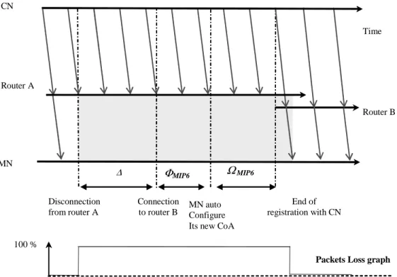
FIGURE II-11IP PACKETS LOSS AS CONSEQUENCE OF MOBILE MOVEMENT 30
FIGURE II-12MOBILE IP NETWORK ARCHITECTURE 33
FIGURE III-1IP HANDOVER DELAY 37
FIGURE III-2TEMPORAL DIAGRAM OF MOBILE IP HANDOVER 39
FIGURE III-3MOBILE IPV6NETWORK 40
FIGURE III-4MOBILE IPV6 HANDOVER PROCESS 41
FIGURE III-5HIERARCHICAL MOBILE IPV6(ONE LEVEL) 43
FIGURE III-6HIERARCHICAL HANDOVERS SIGNALING 44
FIGURE III-7SMOOTH HANDOVER PROCESS 45
FIGURE III-8SMOOTH HANDOVER DATA FLOWS 46
FIGURE III-9FAST HANDOVER PROCESS 48
FIGURE III-10FAST HANDOVER DATA FLOWS 49
FIGURE III-11TCP CONNECTION DURING HANDOVER 55
FIGURE IV-1OVERLAPPING COVERAGE AREAS 61
FIGURE IV-2MULTIHOMING SCENARIOS 62
FIGURE IV-3CONSEQUENCES OF MULTI INTERFACE USE IN MIPV6 63
FIGURE IV-4MULTIHOMING DESIGN POSSIBILITIES 64
FIGURE IV-5MULTIHOMED-MN ADDRESSES MANAGEMENT 66
FIGURE IV-6BINDING CACHE AND DCT STRUCTURES 68
FIGURE IV-7SOFT HANDOVER REGISTRATION PROCESS 70
FIGURE IV-8MULTIHOMING REGISTRATION MESSAGE:MERGING OPTION SIGNALING
MESSAGE 71
FIGURE IV-9DATA IDENTIFICATION OPTION 73
FIGURE IV-10PACKET FORMAT IN THE TUNNEL BETWEEN D&M AGENT AND THE MN 73
FIGURE IV-11SOFT HANDOVER DATA STRUCTURES IN THE NETWORK 74
FIGURE IV-12DOWNLINK DUPLICATION PROCESS IN D&M AGENT 75
FIGURE IV-13UPLINK DUPLICATION PROCESS IN MOBILE NODE 76
FIGURE IV-14MERGING CONTROL TABLE STRUCTURES 78
FIGURE IV-15IPV6 FLOW MERGING ALGORITHM 79
FIGURE IV-16SOFT HANDOVER THRESHOLDS 80
FIGURE IV-17HANDOVER PROCESS 81
FIGURE IV-18SOFT HANDOVER TEMPORAL DIAGRAM 82
FIGURE V-2 FIRST CONNECTION TO AR1 IN GEMINI2 90
FIGURE V-3MOBILE IPV6 AND SOFT HANDOVER FROM AR1 TO AR2 IN GEMINI2 91
FIGURE V-4 IEEE802.11 PROPAGATION MODEL IN GEMINI2 93
FIGURE V-5SIMULATION NETWORK TOPOLOGY. 93
FIGURE V-6MOBILE IPV6 HANDOVERS LATENCY 95
FIGURE V-7AVERAGE END-TO-END TRANSMISSION DELAYS. 96
FIGURE V-8DETAILED MOBILE IPV6 END-TO-END TRANSMISSION DELAYS. 97
FIGURE V-9DETAILED SOFT HANDOVER END-TO-END TRANSMISSION DELAYS. 97
FIGURE V-10END-TO-END JITTERS VARIATION BETWEEN HANDOVERS 98
FIGURE V-11SUM OF RECEIVED PACKETS IN MOBILE IPV6. 99
FIGURE V-12SUM OF UDP RECEIVED PACKETS IN SOFT HANDOVER. 99
FIGURE V-13AVERAGE UDP PACKETS LOSS RATIO 100
FIGURE V-14 FAST HANDOVER BICASTING PROCESS 101
FIGURE V-15SIMULATION NETWORK TOPOLOGY 2 102
FIGURE V-16AVERAGE UDP PACKET LOSS 103
FIGURE V-17AVERAGE UDP TRANSMISSION DELAYS 104
FIGURE V-18DETAILED END-TO-END TRANSMISSION DELAYS (MOBILE IPV6) 105
FIGURE V-19DETAILED END-TO-END TRANSMISSION DELAYS (BICASTING) 105
FIGURE V-20DETAILED END-TO-END TRANSMISSION DELAYS (SOFT HANDOVER) 106
FIGURE V-21HANDOVERS SIGNALLING LOAD 106
FIGURE V-22MOBILE IPV6 THROUGHPUT 107
FIGURE V-23 BICASTING UDPTHROUGHPUT 108
FIGURE V-24SOFT HANDOVER UDP THROUGHPUT 108
FIGURE VI-1HIERARCHICAL D&M AGENTS ARCHITECTURE 111
FIGURE VI-2HIERARCHICAL D&MBINDING ENTRIES 113
FIGURE VI-3 NETWORK TOPOLOGY WITH SINGLE D&M AGENT 114
FIGURE VI-4NETWORK TOPOLOGY WITH HIERARCHICAL D&M ARCHITECTURE 115
FIGURE VII-1PACKET FILTERING ARCHITECTURE IN LINUX 2.4.X 121
FIGURE VII-2MIPL GENERAL ARCHITECTURE 123
FIGURE VII-3D&M ROUTER IMPLEMENTATION OUTLINE. 125
FIGURE VII-4OVERVIEW OF AR AND D&M AGENT STRUCTURES 126
FIGURE VII-5MN IMPLEMENTATION ARCHITECTURE 128
FIGURE VII-6IPV6 PLATFORM 130
FIGURE VII-7ICMPV6 EXPERIENCES SCENARIO 131
FIGURE VII-8AR802.11 CONFIGURATION AND MAP OPTION IN RTADV 132
FIGURE VII-9HOME AGENT BINDING CACHE STRUCTURE 133
FIGURE VII-10D&M AGENT DCT DURING A SOFT HANDOVER 133
FIGURE VII-11DUPLICATED PING6 MESSAGES IN MN 134
FIGURE VII-12DUPLICATED VLCMPEG2 PACKETS RECEPTION IN MN 134
FIGURE VII-13DIO ILLUSTRATION IN DUPLICATED UDP PACKETS 135
FIGURE VII-14LOSS RATIO FOR BIDIRECTIONAL ICMPV6 TRAFFIC 136
FIGURE VII-15 SECOND UDP TESTS SCENARIO 137
FIGURE VII-16 MOBILE IPV6 AND SOFT HANDOVER EFFECT IN UDP THROUGHPUT 138
FIGURE VII-17SIGNAL DEGRADATION SCENARIO 138
FIGURE VII-18UDP THROUGHPUT AND SIGNAL DEGRADATION 139
List of Tables
TABLE 1EXAMPLES OF IPV6 ADDRESS NOTATIONS 21
TABLE 2GENERAL NOTATION. 51
TABLE 3CLASSIFICATION & COMPARISON OF IP-BASED HANDOVER
PROPOSITIONS 52
TABLE 4SUM OF DUPLICATED PACKETS 115
Glossary
2G 3G 4G AP AR BA BC BU CoA CN D&M DAD DCT FBU GPRS GSM HA HiperLan HoA IEEE IETF ICMP ICMPv6 IP IPv4 IPv6 L1 L2 L3 LCoA MAC Madv MCT Mobile IP MIPL Second Generation Third Generation Fourth Generation Access Point Access Router Binding Acknowledgement Binding cache Binding Update Care of Address Correspondent Node Duplication and Merging Duplicate Address Detection Duplication control Table Fast Binding UpdateGeneral Packet Radio Service
Global system for mobile communication Home Agent
High Performance Local Area Network Home Address
Institute of Electrical and Electronics Engineers Internet Engineering Task Force
Internet Control Message Protocol
Internet Control Message Protocol for IPv6 Internet Protocol
Internet protocol version 4 Interne Protocol version 6 Layer 1
Layer 2 Layer 3
Local Care of Address Media Access Control Layer Merging Advertisement Merging Control Table Mobile Internet Protocol Mobile IP for Linux
MN MPEG Msol PCoA RCoA RFC RtAdv RTP Rtsol RTT TCP UDP UMTS WCDMA WLAN Mobile Node
Moving Picture Experts Group Merging Solicitation
Primary Care of Address Regional Care of Address Request For Comments Router Advertisement
Real-Time Transport Protocol Router solicitation
Round Trip Time
Transmission Control Protocol User Datagram Protocol
Universal Mobile Telecommunications System Wideband Code Division Multiple Access Wireless Local Area Network
CHAPTER 1
I.
Introduction
The recent years have seen a rapid development of mobile communication systems. A variety of new wireless radio access technologies such as, UMTS, IEEE WLAN, HYPERLAN and Bluetooth are replacing and augmenting existing GSM radio technology. Therefore, these technologies are not compatible with each others, and each wireless technology provides a tradeoff between coverage range, data rates and costs. On this diversity basis, next mobile networks generation will offer services where users can move freely almost anywhere and communicate with any one, any time, using one or more available services. They support, of course, different radio access technologies and different type of mobility. Users can at any moment manage their connections to fit their application requirements and use the best available and most suitable wireless access technologies. To allow that, future mobile devices will be equipped with more than one network interface in parallel. These interfaces can be from homogenous access radio technologies or can be heterogonous. Using such devices, users can adapt their connection to the current environment and connect many interfaces simultaneously or switch between different technologies if beneficial.
The main goal of mobile communication system is to give the user the freedom of choosing its most suitable communication service at any moment. Mobile communication systems will certainly use IP protocol as universal and common network layer to facilitate the heterogeneous wireless access technologies interconnection and allow the convergence of wireline and wireless communication systems. That will push towards the design of an All-IP wireless and wireline networks, where heterogeneous access wireless networks and mobile devices are under the IP control for signaling and data transmission. In such environment, a true dynamic mobility scenario has to allow the change of mobile user’s connection to the network several times during a single applications session. Moreover, in a heterogonous environment, any user is free to roam its current connection to the network between available access points several times in a session and regardless of their heterogeneity (of course the mobile device has to support desired wireless access technologies).
The grade of service continuity during “the change of mobile user’s connection to the network” (referred to as handover in remains of this dissertation) is crucial to determine the global efficiency of communication
systems. With the deployment of an all-IP mobile communication system, the current increasing demand of IP based multimedia data traffic services compare to the basic voice traffic is encouraged. Regarding the IP based multimedia traffic quality of services requirements compared to voice traffic, new service and communication continuity parameters might be expressed in terms of no data loss, minimal, stable and uniform information transmission delays before and during the handover. This new communication system has to offer, at any moment the best available services to users and propose more sophisticated IP-based handover mechanisms to assure a certain quality of services for dominating multimedia IP traffic in addition to basic voice service continuity. In following, we give some mobile communication systems terminologies and definitions useful for the understanding of remains of this dissertation
1.
Terminology
Today, many heterogeneous radio access technologies coexist, ranging from wireless local area networks (IEEE 802.11 [1][2], Hiperlan [3][4], Bluetooth [5][6]) to outdoor cellular networks (GSM [7][8], GPRS [9], WCDMA [10][11]). These radio technologies are typically not compatible with each others, which make it difficult to perform roaming from one radio network to another. These wireless networks were developed and were evolving independently (e.g., from 802.11/802.11g, from 2G to 3G), but they still have a set of common characteristics and concepts such Wireless cell or coverage area. Wireless cell or coverage area can be defined as the basic service portion of most of Wireless networks. Each one is under the control of an Access Point (AP). An access point is a dedicated node that provides wireless communication services within the coverage area of wireless cell. A set of access points distributed in the coverage area of the network allow the wireless device namely Mobile Node (MN) to keep connection to the fixed network through wireless connections. One of the main characteristic of wireless access technology is the maximal range between the AP and the MN, within this range the MN can receive data from the AP. the area covered by this range is called wireless cell. When the MN is in the center of the cell, the reception quality of wireless connection is optimal, as the MN move away from the cell center; the connection quality degrades progressively toward a complete disconnection outside of the coverage area. When the MN moves out of coverage area of an AP1 and enter the range of a new access point AP2. It disconnects from AP1 and establishes a connection with AP2 that is what we call handover.
Figure I-1 shows a MN performing handover in the border of two coverage areas. A handover is a process that allows the MN to roam from one access point to another while communicating. It transfers the management of MN connection from one access point to another. Both of degradation of wireless connection signal quality when the MN move out of coverage area, and MN disconnection when performing handover, can introduce data loss, additional end-to-end transmission delays and jitters, which perturb the communication.
Old Access Point Cell A Cell B New Access Point Network MN
Figure I-1 MN Handover between two APs
2.
Problem Overview
As stated earlier, next generation networks are expected to integrate many heterogeneous radio access technologies, ranging from indoor wireless LANs to cellular systems. The main reason is that no solution has emerged as universal solution. In the other hand, Internet Protocol (IP)[13][14][15][16][17] is becoming the universal network-layer protocol over all wireless systems, and it is used on the top of all these radio access technologies. That makes the current trend today toward the design of All-IP wireless and wireline networks [18][19], where radio cells are under the control of IP access routers for signaling and data transmission. Mobile IP [20][21] has long been considered as facto standard in providing IP mobility. However, as the demand of wireless mobile devices capable of executing real time applications increases, it has pushed for the development of better IP based handover techniques. The goal is providing a reduced data loss, end-to-end transmission delays and better Quality of services (QoS) support [22]. Several solutions have been designed to improve the QoS in the core of IP-based network, and many others to manage IP-based handover in order to re-establish the IP traffic flow quickly and minimize the service disruption delay that occurs during IP based handover.
In this dissertation, we propose a set of IP based mechanisms to extend mobile IPv6 with bidirectional IP-based soft handover; such solution allows the MN’s session to progress without any interruption and perturbation when it moves from one radio cell to another regardless of their access technologies. To allow an integration of soft handover in mobile IPv6, we have to fix and resolve the following issues:
• The MN must be able to maintain data connection simultaneously with multiple APs at the same time.
• The network and the MN are able to manage the multiple MN connections to the network when using Mobile IPv6 ( multihoming)
• The network must be able, somewhere, to intercept and duplicate IP flows sent by corresponding node to the MN through different ARs • The MN duplicates IP-flows and route them through different access
routers to the network
• The network and the MN correctly merge duplicated flows in a single copy, that can be correctly routed to transport and application layers. • Finally, these mechanisms have to coexist with existing Mobile IPv6
mechanisms. Duplication and merging process should be completely transparent to upper and lower network layers and applications
In addition to the pure problem of soft handover management in IP protocol, which still remains unresolved as explained above. Proposed scheme can be a solution to the general problem of the management of end-to-end quality of service for data communication based on radio transmission. More generally, even when using QoS management mechanisms in the core of the network, there is still a need for improving wireless data communication between a mobile node and IPv6 core of the network, especially in borders of wireless cells. It is an object of present mechanisms to improve the quality of service of wireless data communications using the end-to-end path redundancy and diversity. Particularly for mobile nodes located in the border areas with poor radio coverage from both old and new access routers.
3.
Outline of the Dissertation
The aim of All-IP networks is to allow ubiquitous based access by IP-based MN, with special emphasis on the ability to use a wide variety of wireless and wireline technologies, to access the common information infrastructure. The development of such a mobile device with multiple physical or software-defined interfaces is expected to allow users to switch between different radio accesses technologies. With the extension of basic mobile IPv6 mechanisms using multihoming mechanisms support and soft handover approach, it is possible to eliminate packet loss and reduce jitters and end-to-end transmission delays, which provides a clear advantage to data traffic requiring high level of service. The remainder of this dissertation is organized as follows:
Chapter 2 provides an overview of IPv6 main features and mobility management problems in IP-based networks. We also present main existing intra-technology roaming mechanisms.
Chapter 3 contains a description and analytical analysis of main solutions to manage mobility in Internet protocol; we will focus our analysis in handover management mechanisms.
Chapter 4 describes our mobile IPv6 soft handover mechanisms. We describe the control plane with the introduction of D&M agent and multihoming management. We depict then, the data plane, which allows bidirectional interception, duplication and merging of IPv6 flows.
Chapter 5 analyzes the performance of the IPv6 soft handover in a home made simulator Gemini2. First, simulations evaluate the handover performance gains, and then compare its performance with mobile IPv6 and fast handover bicasting. Chapter 6 contains first, a proposition of D&M agent deployment scheme and protocol. This hierarchical architecture is analyzed than, through simulations Chapter 7 presents our experiences in the implementation of an IPv6-based test bed that support Mobile IPv6. We implement the Duplication &Merging agent in this test bed and additional mechanisms in access routers that allows a dynamic broadcasting of D&M information’s. We implement also a Multi interfaces MN that support soft handover. This testbed allows us to evaluate the performance of soft handover in real network using real time applications. Finally Chapter 8 outlines remarks and summaries of our work and contributions. We discuss the general experience learned about the design of an IPv6 based soft handover mechanisms and outline some directions for future research.
4.
PhD Related publications and Applications
Journal Papers
• Farouk Belghoul, Yan Moret, Christian Bonnet « Mécanismes de Handover pour les réseaux IP sans files” " Technique et Sciences Informatiques, TSI " journal, Revue des sciences et technologies de l'information Vol. 24, No 1/2005.
• Farouk Belghoul, Yan Moret, Christian Bonnet “Prototype Implementation and evaluation study of Mobile IPv6 soft handover mechanisms ” to be Submitted to WILEY Wireless Communication and Mobile Computing .June 2005
• Fethi fillali, Farouk Belghoul, Christian Bonnet & All “” An Open, Pluggable, and Flexible Software-Radio Platform for Heterogeneous Wireless Networks” to be submitted to ACM Mobile Networks and Applications (MONET) June 2005.
International Conferences Papers
Farouk Belghoul Yan Moret, Christian Bonnet “A Multilevel Hierarchical topology of DM agents for MIPv6 Soft handover ” World Wireless Congress SanFrancisco, USA 2004 PP 56-60
Farouk Belghoul Yan Moret, Christian Bonnet “ Performance comparison and analysis on MIPv6, fast MIPv6 bi-casting and Eurecom IPv6 soft handover over IEEE802.11b “ 59 IEEE VTC, MILAN 2004 Vol.5 PP 2672- 2676
• Farouk Belghoul Yan Moret, Christian Bonnet “ Performance analysis on IP- based soft handover across ALL-IP wireless networks” IWUC, PORTO, Portugal 2004
• Farouk Belghoul Yan Moret, Christian Bonnet “ IP-based handover management over heterogeneous wireless networks” LCN 2003, 28th Annual IEEE Conference on Local Computer Networks, October 20-24, 2003, Bonn, Germany PP 772- 773
• Farouk Belghoul Yan Moret, Christian Bonnet “Eurecom IPv6 soft handover:” ICWN 2003, International Conference on Wireless Networks- June 23th - 26th, 2003 - Las Vegas, USA PP 169-174
Applications
• GEMINI2: a wireless and wireline simulator written in C++. It supports IEEE802.11b, Ethernet, IPv6, MobileIPv6, Fast Handover, Soft handover, multihoming, and multi-interfaces mobile.
• Mobile IPv6 Soft handover platform: a soft handover on 802.11b platform test, based on Linux 2.4.18 and MIPL 0.9.3, that support multihoming and multi interfaces mobiles.
CHAPTER 2
II.
State of the Art
This chapter gives first a short overview of handover classification in existing mobile communication systems; with special emphasis on the new requirements of handover designs for All-IP wireless networks. In this context of All-IP mobile communication system, the main features and functionalities of the latest version of Internet Protocol (IPv6) are presented. We specially focus in useful mechanisms to understand the mobility management in Internet Protocol in the remainder of this dissertation. We depict the IP nodes autoconfiguration mechanisms, IP packets tunneling and the opening of the IPv6 protocol to the future development via the option headers. That leads directly to the fundamental mobility problem in Internet Protocol. The problem is clearly defined and the requirements for the design of mobility schemes are elaborated. Finally, mobile IP, the classical solution for mobility support in IP is proposed.
1.
Handover in Mobile Communication Systems
Handover in existing mobile communication systems differs greatly, and many classifications of handover following different criteria have been done. In following, we summarize general handover types and their classification criteria • Topology and location of access points
Local Handover. In a local handover the mobile node roams between two access points that belongs to the same network, or the same domain.
Global Handover. In a global handover the mobile node roams from an access point to a new one that not belongs to the same network or domain.
• Access points wireless technologies
Horizontal handover. It is a handover between access points using the same wireless access technology. A typical example is handover between two access points using UMTS access technology.
Vertical handover. It is a handover between access points using heterogeneous wireless networks such as handover between WCDMA access point and IEEE 802.11 access point.
• Handover initiation
Mobile-initiated handover. The mobile node, as well as the target access point takes the handover decision. Usually the mobile node triggers the handover when the quality of the current signal decreases under a given threshold. Network-initiated handover. In this approach, the Network is able to determine the appropriate new access point of the mobile node, and uses this information to initiate the mobile node handover.
• Number of simultaneous connections to access points
Hard Handover. Called also break-before-make, in this handover family used in WLAN, WCDMA or TDMA [12], the MN can keep connection through only one access point. The mobile node disconnects from the old access point than initiates connection through the new one to perform a handover.
Soft Handover. In the soft handover, the MN can communicate simultaneously with more than one access point, in our example, the old and the new access points. This handover can be seamless but it requires an overlapping region between the old and the new access point to. An additional benefit of soft handover is that the duplication of connection in overlapping area can improve the global quality of mobile connection of the mobile node to the fixed network. The connection is duplicated by sending and receiving the same data through two access points
In second generation mobile networks (GSM), the hard handover was designed for voice traffic. It is achieved via a change of the channel used by the mobile node. The system continually measures the level and the quality of the signal received from the neighbor cells. As soon as the current communication quality goes below a certain threshold, the network decides to change the mobile node radio channel. It chooses another one with a better quality of signal. This procedure was optimized for data voice traffic with strong traffic synchronization mechanisms which allow the reconstruction of lost traffics when performing the handover. Note also that the QoS requirements were not heavies because of the permissibility of human ear.
The massive success of 2G technologies is pushing mobile networks to grow extremely fast as ever-growing mobile traffic puts a lot of pressure on network capacity. In addition, the current strong drive towards new applications, such as wireless Internet access and video telephony, has generated a need for a universal standard at higher user bit-rates. This led the definition of third generation 3G digital cellular systems, standardized in Europe by ETSI (European Telecommunication standards Institute) as UMTS (Universal Mobile telecommunications Systems). Considering third generation networks, in addition to the traditional hard handover mechanism, the soft handover concept is introduced. In the CDMA network such as IS-95 [23], the mobile station can be connected to multiples base station simultaneously. A centralized selection and distribution unit (SDU) is responsible for data distribution in the downlink. It creates and distributes multiples streams of the same data over layer2 circuits to the direction of the mobile terminal through different base station. A strong synchronization mechanism is required, duplicated packets of data arriving from
different radio gateways to the MN, must arrive in the same time, to allow the Mobile to combine them in a single copy, which reduces the overall packet loss. On the other hand, compared with the conventional hard handover, soft handover has the advantages of smoother transmission and less ping-pong effects. As well as leading to continuity of the wireless services, it also brings macro diversity gain to the 3G system. For the purpose of next all-IP heterogeneous mobile communication networks, and the convergence wireless and wireline, the increasing demand of IP based multimedia data traffic services compare to the basic voice traffic is encouraged. Regarding the IP based multimedia traffic quality of services requirements compared to voice traffic, the introduction of new IP efficient handover mechanisms seem to be the most suitable solution to allow a session continuity even when the MN change its point of attachment to the network, regardless of their radio access technologies and with minimal QoS. In chapter III we will detail existing solutions to manage handover in internet protocol. But note that there is no already standard to extend the IP mobility management with soft handover mechanisms.
2.
Internet Protocol Next Generation
The latest version of the Internet Protocol, namely Internet Protocol Version 6 or simply IPv6 [24][25], is a very promising network layer. It is the core of new communication possibilities and services in the future networks. The IPv6 version of the Internet network substantially differs from the known IPv4 version and provides additional features and new possibilities. The main need to imagine a new version of Internet Protocol appears with the fast growing of IP networks and the limitation of address space in IPv4 [26]. This section describes the other important innovations of IPv6 over IPv4. Because of the complexity of IPv6, our focus lies on its features which can be used in mobility management and therefore the understanding of the remainder of this dissertation.
2.1. Expanded Addressing Capability and Autoconfiguration
Mechanisms
In order to solve the problem of the limited address space of IPv4 and in order to offer a deeper addressing hierarchy and simpler address configuration mechanisms, the Internet addressing capabilities have been increased from 32 bits in IPv4 to 128 bits in IPv6. This address space extension in IPv6 requires a new address format. The new preferred form is the hexadecimal notation “X:X:X:X:X:X:X:X”. ‘X’ is a group of 4 hexadecimal numbers, each one represents a piece of 16 bits of the IPv6 address (e.g., “fe80:202:0000:0000:0000:7654:fedc:3210”). Since, it is assumed that an IPv6 address can contain many successive groups of zero, a special compressed representation were defined. The special notation “::” can be used once in the address, it indicates a multiples successive groups of zeros, (e.g., the above IPv6 address can be represented by “fe80:202::7654:fedc:3210” as described in Table 1). IPv6 address is the only way to identify an IPv6 node in the network, IPv6 routing mechanisms are based on this address to route correctly data to the destination node. IP address merges in a single key both identification and
location of each component of the Internet Protocol. Any IPv6 address can be classified into one of three categories: Unicast, anycast and multicast address. The unicast address uniquely identifies an interface of an IPv6 node; any IPv6 packet sent to a unicast address is delivered to the corresponding interface. This kind of address is split in his turn into two forms, link-local address and site-local address.
The link-local address is the address that is exclusively used within the boundaries of a link and is defined on the basis of the Interface IDentifier (IID) [27] assigned to the interface. The IID must be unique on the link and is derived from the hardware interface card address, the form of a Link-local address is “FE80::X:X:X:X”.
The Site-local address is designed for networks that are not reachable from the outside, they have only local routability scope, and any IPv6 packet with site-local address will not be routed outside the corresponding networks. The format of site-local address is “FEA0::X:X:X:X”.
The multicast address identifies a group of IPv6 interfaces. Unlike repeated unicast transmission of packets to multiple nodes, all members of the multicast group process a packet sent to a multicast address.
The anycast address is a new kind of address introduced in IPv6. It is a mixture between unicast and multicast addressing principles, this address identify a group of interfaces; a packet sent to an anycast address will be delivered to the nearest interface of the anycast group. The Table1 illustrates valid examples of IPv6 address in long and compressed notations.
IPv6 address format Long notation example Compressed notation Unicast link-local FE80:0:0:0:12e0:18ff:fea8:abde FE80::12e0:18ff:fea8:abde Unicast Site-local FEA0:0:0:0:12e0:18ff:fea8:abde FEA0::12e0:18ff:fea8:abde Multicast address FF02:0:0:0:0:0:0:1 FF02::1
Loop-back address 0:0:0:0:0:0:0:1 ::1
Unspecified address 0:0:0:0:0:0:0:0 ::0
Table 1 Examples of IPv6 address notations
Neighbor Discovery protocol (ND) [28] is the process used in IPv6 to allow nodes discovery on the same link. This protocol allows each node to discover its neighbor’s link-layer addresses, find routers, learn about further link properties and auto-configure its own valid IPv6 address. The procedures involved in address autoconfiguration are as follows:
Parameter Discovery, used to discover particular parameters and/or options concerning the link, including prefixes.
Address Configuration, used for automatic configuration of an interface's address.
Duplicate Address Detection: an algorithm used to check that an address to be assigned is not already in use.
There are five different ICMPv6 [29][30] messages for this protocol: Router Solicitation, Router Advertisement ( RtAdv), Neighbor Solicitation, Neighbor Advertisement, and Redirect. The most important message for the remained of the dissertation is the router advertisement. Each IPv6 node can advertise a Router Advertisement Message within its different interfaces. This message advertises neighbors about the node presence in the network and its Internet parameters. The format of an RtAdv message is depicted in Figure II-1.
Figure II-1 Router Advertisement Packet Format
The hop limit field specifies the max hop limit of the router advertisement message, the M and O flags are used for the stateful address autoconfiguration mechanisms, Router lifetime indicates the life time of the message in seconds, the reachable time is assumed to be the time, in seconds, that the router is considered is reachable after getting the reach ability confirmation, the retransmission time define the message advertisement frequency. The options field is used by router advertisement daemon to advertise optional message. The RtAdv message can be generated periodically by the router within a retransmit time, or can be an answer to an RtSol message. In fact when an IPv6 node enables a link with a router, it may wait for router advertisement message or can generate RtSol message, which requests the router to generate RtAdv message immediately rather than waiting a total Retransmit Time delay.
The attachment of a mobile node to an IPv6 network is greatly facilitated by a set of mechanisms named address auto-configuration mechanisms. They allow every mobile node, or any communicating device, to configure its own IPv6 address in its new sub network. These mechanisms are based on combination of the unique interface Identifier and a set of information received from the access point serving as physical attachment link, through an RtAdv message. IPv6 defines both a stateful and stateless address autoconfiguration mechanisms. Stateless autoconfiguration [31] takes place automatically as soon as the mobile node interface is enabled. This one starts the autoconfiguration process by registering in the multicast group “FF02::1” which identifies all of the nodes in the same link so that it can receive messages originating from the routers using this destination address. The station then sends a RtSol message with destination address field is set to the all-routers multicast address “FF02::2” in this message. The AP responds with a RtAdv, one or more AP prefix options can be specified in this message. At this moment the mobile node can start stateless configuration
Reachable Time Retransmit Time
Options
Checksum
Type Code
protocol to build its valid IPv6 address by concatenating the address supplied to it by the prefix option with its unique IID (Figure II-2). This only applies if the prefix is not too long, and otherwise will be ignored. After a mobile node has obtained a unicast address using stateless address autoconfiguration, it must check that it is unique before assigning it to the interface. To do so, the mobile node applies the Duplicate Address Detection (DAD) protocol. It sends a Neighbor Solicitation message in which the source address field is set to the unspecified address and the destination address field is set to the solicited-node multicast address. If the same unicast address has already been assigned to another node, the latter will respond with a Neighbor Advertisement. If the mobile node receives this message, it disables the use of the address that has just been obtained.
IPv6 Access Point
IPv6 Network MN
RIID: Router IID P: all on-link Prefixes IID: interface IID
Link-local address: FE80::IID
S@ FE80::IID,D@ FF02::1:FF:IID RS, @FE80::IID
@FE80::RIID,@FE80::IID RA, @FE80::RIID,P Request: Router solicitation
1
2
1
Answer: Router Advertisement
Router Advertisement Broadcasted periodically Solicited Router
Advertisement
Unsolicited Router
Advertisement @FE80::RIID,@FE80::IID RA, @FE80::RIID,P
Figure II-2 Address autoconfiguration mechanisms
In the stateful autoconfiguration model, the mobile node obtains interface addresses and/or configuration information and parameters from a server. Servers maintain a database that keeps track of which addresses have been assigned to which node. The stateful autoconfiguration protocol allows IPv6 nodes to obtain addresses, other configuration information or both from a Dynamic Host Configuration Protocol (DHCP) server [32].
2.2. Simplification of the Header Format
In order to simplify and reduce the cost of Internet protocol packet routing and processing, the IPv4 header format have been changed. The new IPv6 header [25] has a fixed total length of 40 bytes as shown in figure II-3. In this figure we compare an IPv6 packet header to an IPv4 header, which includes 12 fields in its 20 byte of length. Some fields of the IPv4 header have been removed or become optional. This way, packets can be handled faster and easier. The
IPv6 header consists of two parts, the basic IPv6 header (as illustrated in Figure II-3) and optional IPv6 extension headers. The usage of the fields conveyed by the IPv6 header is summarized in following.
• Version (4 bit): Indicates the protocol version, and will thus contain the number six to denote IPv6 protocol.
• Traffic class (8 bit): This field is used by the sending source and routers to identify the packets belonging to the same traffic class and thus distinguish between packets with different priorities and allow Quality of Service management in routing mechanisms.
• Flow label (20 bit): Label for a data flow.
• Payload length (16 bit): Indicates the total size of the packet data field. • Next header (8 bit): Identifies the type of header immediately following the
IPv6 header. Which can be an option header as explained in next paragraph • Hop limit (8 bit): Decremented by one by each node that forwards the
packet. When the hop limit field reaches zero, the packet is discarded. • Source address (128 bit): The address of the IP node originator of the
packet.
• Destination address (128 bit): The address of the recipient of the packet.
(a) (a)
(a) (IPv6)
Flow Label Traffic Class
Next Header Hop Limit Source Address Payload Length Destination Address Version Total Length IHL
Class
FlagsHeader
Fragment Offset Time to LiveVersion Service Type
Source Address
Destination Address
Option and Padding Identifier
Protocol Header Checksum
Note that additional header fields besides the source and destination address in IPv6 were reduced to only 6 scattered over 40 bytes compared to the IPv4 header, which carries 10 fields in 20 bytes. In particular, the Header Length (the length of the IPv6 header is fixed to 320 bytes), the Identification, the D- and M- flags, the Fragment Offset and the Header Checksum field from IPv4 header were dropped or made optional in IPv6 extension headers. Even though the IPv6 addresses are four times longer than the IPv4 addresses, the header itself is only twice the size.
2.3. Improved Support for Extensions and Options
In IPv4, options fields were integrated into the main IPv4 header. Within IPv6, they are handled as Extension headers. Extension headers are optional and only inserted after the IPv6 header. As a direct consequence, forwarding IPv6 packets becomes much more efficient. New options that will be defined in the future can be integrated easily. The basic format of an extension option header is depicted in the following figure.
Next Header Ext Hdr Len
Extension Header specific Data
Figure II-4 IPv6 Extension Header Format
An IPv6 packet can have more than one type of extension header; each next header type is determined by the Next Header field of the previous packet header or extension header. These packets headers will be processed only in the destination node, and in the order of their occurrence, except the hop-by-hop extension header. All routers in the packet delivery path can process the hop-by-hop header, so it must be in the first position. The figure shows how option headers can be used:
IPv6 Header Next Header = UDP
UDP header + Data
IPv6 Header Next Header = Routing Routing header Next header = DestinationOpt DestinationOpt Next Header = UDP
UDP Header + Data
Figure II-5 Example of the use of IPv6 extension headers
Any full IPv6 implementation has to support the following packet header extensions:
• Hop-by-Hop: this header is processed by every passed IPv6 router, it holds optional information relevant for these routers on the packet way to the destination. The information that carries the Hop-by-Hop option or destination option is structured on one or more TLV (Type-Length-Value).
Option Type Opt Length Option Data Note that one or more TLV can be inserted in each option header.
• Destination Option: This option header is quit similar to the hop-by-hop option header; the difference is that the destination option conveys special option that requires processing only in the destination node.
• Routing Header: This option holds information that specifies a set of routers that the IPv6 packet has to visit along the path to the destination node. This option corresponds to the source routing in IPv4. The routing header has the following format:
Figure II-6 Format of an IPv6 Routing Header
The “segments left” field specifies the number of explicitly defined router that the packet has to visit.
Figure II-7 is a practical example of the forwarding of an IPv6 packet with a routing header .the followed IPv6 packet should be routed from mode @ to @’, over the intermediate routers @1 and @2. When processed the node swaps the destination address and segment left address and decrements the segment left. • Fragment option header: When the global IPv6 packet size is larger than
the Maximum Defined Transfer Unit (MTU) of a connection, the fragment Address n
..
..
Address 1
Routing Type Next Header Header Length
Reserved
header is used for the fragmentation of the packet to smaller fragments and then to reassemble these fragments
• Authentication: this header is used to ensure the integrity and the authentication for the IPv6 packets during a session between sender and receiver [33].
• Encapsulation: an encapsulation header guarantees confidentiality (between source and destination) for the reminder of the packet.
•
@, @1
2, @2, @
’
data
@, @2
1 @1, @’
data
@, @’
0, @1, @2,
data
@2
@’
Internet
Nodes
@1
@
Figure II-7 Source Routing in IPv6.
For the purpose of our dissertation, a special option for destination header has been defined in our IPv6 stack, named Duplication Information Option. This header will be detailed in the third chapter; it can be processed only by received node, and will be exploited in our proposed mechanisms to mange packets duplication and merging in MobileIPv6 soft handover.
2.4. IPv6 in IPv6 Packet Encapsulation ”IPv6 Tunnels”
IPv6 tunnels are an IPv6 concept that will be used frequently in the rest of this dissertation. The IPv6 tunneling [34] is a technique for establishing a "virtual link" between two IP nodes for transmitting data packets as payloads of other IPv6 packets, using a new IPv6 header, source and destination address, as described in Figure II-8 . In this figure all IPv6 packets sent by node @1 to node @2 are intercepted by router S and tunneled to router R. This one decapsulates received packets and route them to the final destination @2. This IPv6 "virtual link", named an IPv6 tunnel, appears as a point-to-point IPv6 link by which packet is encapsulated and carried as payload within another IPv6 packet. The tunnel is unidirectional and the two IPv6 nodes are identified by their IPv6
unicast addresses. The tunnel sender-node encapsulates IPv6 packets forwarded or intercepted from other nodes or just itself and forwards the resulting new packets through the tunnel. The receiver-node decapsulates tunneled packets at reception; it applies, then, the basic IPv6 routing process to the resulting initial packets.
Tunnel
Router S
encapsulation
Router R
decapsulatio
n
@1 @2 Payload
@1 @2 Payload
@S @R @1 @2 Payload
Figure II-8 example of IPv6 tunnel
Tunnel 1
Node S
Node R
@3 @4 Payload
@1 @2 Payload
@S @R @1 @2 Payload
Tunnel 2
@R @S @3 @4 Payload
@3@4 Payload
@1 @2 Payload
In our soft handover approach, we will use a bi-directional IPv6 tunneling to carry data between the mobile and the network. Such as concept, is achieved by merging two basic unidirectional tunnels. We need to configure two tunnels; each in opposite direction to the other, the sender node of first tunnel is the receiver node of the second tunnel as indicate the figure II-9.
In the encapsulation process, a new IPv6 header is added to the original packet, the source field of the added IPv6 header is filled with an IPv6 address of the tunnel sender node. The destination field is filled with an IPv6 address of the tunnel receiver node. The resulting packets from encapsulation are than sent automatically to the receiver node. The encapsulated packets sent through the tunnel are then routed by intermediate routers in the tunnel way, according to the basic IPv6 routing mechanisms. The following figure depicts the format of an encapsulated packet.
Original IPv6 Header
Payload
IPv6 Header IPv6 Extension header
Original IPv6 Header
Payload Original IPv6 packet Tunneling
Additional IPv6 tunnel header
Figure II-10 Packet encapsulation
3.
Internet Protocol and Mobility Requirements
As detailed in previous paragraph, Internet Protocol (v4, v6) has traditionally been designed for fixed networks. Each correspondent node is assumed to get connection to the network through the same link in a fixed subnetwork. A fixed IP address identifies the link of correspondent node in the network and allows IP packet to be routed correctly to the destination node. The IP address, considered as a base of an Internet networks, merges in a single key both identification and location of each components of the Internet Protocol.
The mobility management problem appears when a fixed node in the IP network becomes mobile while communicating with another node, and moves from its old location to a new sub network, by performing a handover from one access point to another one. The direct consequence is that its old IP address becomes topologically incorrect. Moreover any current correspondent node, without additional IP mobility information, will continue to use this erroneous IP address to identify the mobile node, and all packets sent by the correspondent node will
use this obsolete address as destination address. Intermediate routers in the core of the network will, logically, route sent packets to the old location of the mobile using the IP normal routing mechanisms. As direct consequence, all packets sent after the mobile node movement will be simply lost, as illustrates the scenario in Figure II-11. @IP1 @IP? IP1data IP1data IP1data IP1data IP1data IP1data IP1data IP1data
IP node change its physical link to the network
Figure II-11 IP packets loss as consequence of Mobile movement Therefore, the first natural solution that can be proposed to resolve this problem is to assign automatically a new topologically correct IP address to the mobile node after each physical handover. This address will correctly identify the mobile at its new location in the network, so it can be reachable at this address. Unfortunately this solution is not sufficient, to understand the reason, we take a look to an application which generates data over an IP- based network; For example, if an application establishes a TCP or UDP session between a correspondent node and mobile node through Internet Protocol, it takes the IP addresses of correspondent and the mobile as node-id for application session. If the mobile nod moves during this session, it changes its connection to the network from an old access point to a new one that can be not in the same subnetwork. If we apply the early solution, the mobile node will get a new IP addresses automatically to identify its new location, however the session can not be continued, the mobile–id in application session does not longer match the new subnetwork of the Mobile node. All packets sent from correspondent node to the mobile node during this session after mobile movement will be simply lost. The use of IP address as key to identify the mobile and its location in Internet network is the fundamental mobility problem in Internet Protocol, we need solution that guarantee that any mobile node can be able to receive its ongoing communication in any place and, the most important, maintain its application session continuity after a physical handover.
Any IP based mobility management scheme shall support the mobile node initial identification and registration, physical handover detection, allow new IP
address configuration, introduce an address registration mechanisms to keep trace of mobile location from the IP view (introduce a dynamic address binding), and extend IP routing mechanisms to forward mobile destined IP packets to its real location at any moment.
• The initial registration and identification is a process by which a network becomes aware of the existence of a special IP node with mobility capability and its associated user. When a Mobile node becomes active (i.e., is turned on) in a network, it shall be registered with the network. This process comprises sending an identity registration request from the Mobile Node to the network, and performing an AAA (i.e., authentication, authorization, and accounting) process by the network. This registration process should occur when the user turn on its mobile node in the network or when it performs handover to a new administrative domain (there is new entity to mange the mobility in the new network).
• A physical handover detection mechanism in network layer is a process by which the IP layer of the mobile node becomes aware of the occurrence of physical handover. If there is no interaction between the IP layer and the link layer of the mobile node, it is necessary to introduce IP based mechanisms allowing the mobile to check, regularly, the IP sub-net address of its access point, and detect any elements that can indicate a physical handover and, if possible, the type of the handover.
• After detecting a handover, the mobile node needs to process an IP address Configuration mechanism. This is the process by which the mobile updates its IP address as a consequence of handover either within the same administrative domain or in different administrative domains. As an Mobile node moves between two different sub-networks or networks, it needs to acquire a new IP address, possibly new default gateway, subnet mask, etc. as well, and to reconfigure itself accordingly as described in previous paragraph.
• Dynamic address registration and binding is a process for allowing a mobile to maintain a constant identifier (e.g., a constant URL) for application in upper layer, regardless of its point of attachment to the network (e.g., its IP address). In such as process, after initial identification of the mobile node in the mobility administration entity of the network, as consequence of a handover, the mobile have to register its new IP address within the entity. The results are that the mobile node can maintain its initial identifier as universal identifier regardless of its point of attachment. Needless to say that such as process require an additional special singling mechanisms
• Mobile node binding address management and packets redirect is a process by which the network stores and updates the mobile location
database and supports location/redirect services if IP packets to the mobile node. This service is essential for any open session during and after a mobile handover. The requirements of location management are accuracy, being up to date, and simplicity of database and confidentiality of the location information. So we need to introduce a new entity in the network that can manage mobile nodes mobility location and packets redirection
.
3.1. Mobile IP
Mobile IPv4 [20][21] or simply mobile IP or MIP is the oldest and the simplest way to introduce mobility management in the Internet Protocol. Its simplicity and scalability gives it a growing success. Several Internet drafts and publications have proposed various improvements for Mobile IP [36][37]. The basic principle of this approach is the use of a couple of addresses to identify the mobile node and manage its movements. Mobile IP and its successor mobile IPv6 define the following basic entities that will be used across the dissertation to refer to its features. The Figure II-12 illustrates the main features.
• Mobile Node: A mobile node (MN) is an Internet node or a host that can change its point of attachment to the Internet from one network to another while maintaining any ongoing communications.
• Home Address (HoA): A mobile node home address is an IPv6 address that has been assigned to the mobile node permanently. This home address does not change when the mobile node moves from one network to another. This address will not change usually. A mobile nodes Home address will only change under certain circumstances. Any application uses this address to identify the MN regardless of its location.
• Home Link: In the core of the Internet network, a home link subnetwork addresses space is used as base-network for mobile nodes. The IP prefix of the home link allows the definition of the mobile nodes home address • Home Agent: a home agent (HA) is a router with at least one network interface on the mobile nodes home link. It is responsible of keeping MN addresses binding and packets redirection, when the MN is away from its home network.
• Foreign Link: a foreign link is any network to which a mobile node is connected to, away from its home network.
• Access router: an access router (AR) is the last router between the network and the mobile node, i.e. the mobile node has link layer connectivity to the core of the network through the access router. • Care-of Address: a care-of address (CoA) of a mobile node basically
refers to the second IPv6 address of the mobile node. The care-of address associated with a mobile node is the IPv6 address, which the mobile node has, when it is visiting a foreign link. In mobile IPv6, the care-of-address is always a collocated one, which is an IPv6 address temporarily assigned to an interface of the mobile node itself. Only one mobile node can use a particular care-of address at a time.
• Binding Update: It is a signaling message issued by the MN. It contains the new CoA and information in a MN's registration request
• Binding Cache: The binding cache is a table maintained by each home agent and correspondent node (only in Mobile IPv6) that contains the current bindings for mobile nodes. Each binding cache entry contains the main following information:
The home address for the mobile node The care of address for the mobile node The lifetime of the binding cache entry
• The binding update list is maintained by a mobile node to record the most recent binding updates sent for the home agent and correspondent nodes (only in Mobile IPv6). A binding update list entry contains a set information such :
The address of the node to which the binding update was sent The home address for the binding update
The care of address sent in the last binding update and the remaining lifetime of the binding entry.
Access Router Foreign Agent Binding cache(HoA,CoA) Home link Foreign network MN Internet 1 2 3
1. MN Connection and foreign agent discovery 2. Foreign Agent attributes a CoA to the MN
3. MN registers its CoA within its HA.
Correspondent node
Home Agent
CoA