HAL Id: tel-03174262
https://tel.archives-ouvertes.fr/tel-03174262
Submitted on 19 Mar 2021HAL is a multi-disciplinary open access archive for the deposit and dissemination of sci-entific research documents, whether they are pub-lished or not. The documents may come from teaching and research institutions in France or abroad, or from public or private research centers.
L’archive ouverte pluridisciplinaire HAL, est destinée au dépôt et à la diffusion de documents scientifiques de niveau recherche, publiés ou non, émanant des établissements d’enseignement et de recherche français ou étrangers, des laboratoires publics ou privés.
and Orientation Workspaces
Saman Lessanibahri
To cite this version:
Saman Lessanibahri. Cable-Driven Parallel Robots with Large Translation and Orientation Workspaces. Robotics [cs.RO]. École centrale de Nantes, 2020. English. �NNT : 2020ECDN0006�. �tel-03174262�
T
HESE DE DOCTORAT DE
L'ÉCOLE
CENTRALE
DE
NANTES
COMUE UNIVERSITE BRETAGNE LOIRE
ECOLE DOCTORALE N°602 Sciences pour l'Ingénieur
Spécialité : Robotique - Mécanique
Cable-Driven Parallel Robots with Large Translation and Orientation
Workspaces
Thèse présentée et soutenue à Nantes, le 12 mai 2020
Unité de recherche : Laboratoire des Sciences du Numérique de Nantes (LS2N)
Par
Saman LESSANIBAHRI
Rapporteurs :
Marc GOUTTEFARDE Directeur de recherche, Université de Montpellier Med Amine LARIBI Maître de conférences HDR, Université de Poitiers
Composition du Jury :
Président : Marc GOUTTEFARDE Directeur de recherche, Université de Montpellier Examinateurs : Coralie GERMAIN Enseignante Chercheuse, Agrocampus-Ouest, Rennes
Darwin LAU Professeur assistant, Université Chinoise de Hong Kong, Chine Dir. de thèse : Stéphane CARO Directeur de recherche, École Centrale de Nantes
iii
Résumé
Les Robots Parallèles à Câbles (RPC) sont considérés comme des manipulateurs parallèles avec des câbles flexibles au lieu de liens rigides. Un RPC se compose d’un bâti, d’une plate-forme mobile et de câbles les reliant l’un à l’autre. Les RPC sont réputés pour leurs performances avantageuses par rapport aux robots paral-lèles classiques en termes d’espace de travail en translation, de reconfigurabilité, de capacité de charge utile importante et de performances dynamiques élevées. Cepen-dant,l’amplitude de rotation de la plateforme mobile des RPC est généralement lim-itée en raison des collisions de types câble/câble et câble/plateforme mobile.
De nouveaux concepts sur le potentiel des RPC avec un espace de travail en orientation très large ont été introduits dans la littérature. L’un de ces concepts sug-gère l’utilisation d’un circuit de câble bi-actionné pour l’actionnement à distance d’un mécanisme parallèle intégré dans la plateforme mobile des RPC, formant des manipulateurs hybrides. Ces manipulateurs sont hybrides parce qu’ils combinent les avantages d’un grand espace de travail en translation des RPC et de grandes am-plitudes de rotation des poignets actifs. Même s’il s’agit d’un concept prometteur pour l’augmentation de l’espace de travail en orientation des RPC, au meilleur de la connaissance de l’auteur, il n’a pas été réalisé. Les circuits de câble bi-actionnés, à savoir les boucles de câbles, sont l’essence même des RPC hybrides munis d’une plateforme articulée et actionnée au moyen de moteurs fixés au sol. Par conséquent, les plateformes mobiles n’ont pas besoin d’actionneurs embarqués, ce qui réduit l’inertie des parties mobiles des manipulateurs. Ainsi, l’objectif principal de cette thèse de doctorat est ainsi de concevoir, d’analyser et de prototyper des RPC hy-brides ayant à la fois un grand espace de travail en translation et un grand espace de travail en orientation en utilisant des boucles de câbles.
Ce manuscrit est composé de cinq chapitres. Le premier chapitre présente des robots parallèles à câbles existants, l’état de l’art des manipulateurs hybrides, les concepts fondamentaux ainsi que les contributions de ce manuscrit.
Le deuxième chapitre traite de l’étude, de l’analyse et de la conception d’un manipulateur parallèle à câbles planaire composé d’une paire de câbles et dédié à des opérations de manutention dans de grands espaces. L’objectif principal est l’étude d’une approche innovante pour la construction de RPC hybrides par le biais de boucles de câbles. La modélisation, l’analyse et la conception optimale du RPC hybride proposé sont présentées dans le chapitre.
Un RPC muni d’un poignet à deux degrés de liberté est étudié dans le troisième chapitre. Le manipulateur combine les avantages des RPC, c’est-à-dire un grand espace de travail en translation, avec ceux des poignets, à savoir des amplitudes de rotation importantes autour de deux axes. L’effecteur comprend également huit degrés de liberté (ddl) contrôlables.
poignet sphérique d’architecure parallèle à trois degrés de liberté intégré et un es-pace de travail en orientation considérablement augmenté. La plate-forme mobile sous-actionnée possède neuf degrés de liberté.
Finalement les conclusions et les perspectives pour les travaux futurs sont présen-tées dans le cinquième chapitre. Les recherches menées dans le cadre de cette thèse proposent des solutions inédites pour les RPC à grands espaces de travail en trans-lation et d’orientation.
Mots clés: robot parallèle à câbles, robots hybrides, espace de travail, boucles de câbles, conception, poignet à deux degrés de liberté, poignet sphérique
v
Abstract
Cable-Driven Parallel Robots (CDPRs) also noted as wire-driven robots are parallel manipulators with flexible cables instead of rigid links. A CDPR consists of a base frame, a platform and a set of cables connecting in parallel the moving-platform to the base frame. CDPRs are well-known for their advantageous perfor-mance over classical parallel robots in terms of large translational workspace, re-configurability, large payload capacity and high dynamic performance. They have drawn interests towards industry thanks to their fundamental advantages and ca-pabilities. However, most of the CDPRs provide only limited amplitudes of rotation of the moving-platform due to collisions between the cables and the moving parts.
Novel concepts towards the potential of CDPRs with drastically large orienta-tion workspace have been introduced in literature. One of those concepts suggests using a bi-actuated cable circuit for remote actuation of a parallel mechanism em-bedded in the moving-platform of CDPRs, forming hybrid manipulators. Those manipulators are hybrid because they combine advantages of large translational workspace of CDPRs and large rotational amplitudes of active wrists. Even though it is a promising concept for augmentation of orientation workspace of CDPRs, to the best of author’s knowledge, it has not been realized. Bi-actuated cable circuits, namely, cable-loops are the essence of the hybrid CDPRs with augmented orienta-tion workspace, since they transmit power directly from motors fixed on the ground to the moving-platform. Consequently, the actuators do not have to be mounted on the moving-platform, which leads to lower inertia of the moving parts of the ma-nipulators. The main objective of this doctoral thesis is to design, analyze and pro-totype hybrid CDPRs to enlarge the orientation workspace in addition to their large translational workspace by exploiting cable-loops.
This manuscript is composed of five chapters. The first chapter introduces CD-PRs, the state of the art related to hybrid manipulators, the fundamental concepts and contribution of the manuscript.
The second chapter deals with the study, analysis and design of a planar cable-driven parallel crane as the fundamental step for construction of hybrid CDPRs with large translation and orientation workspaces. The primary objective is the investi-gation of an innovative approach for construction of hybrid CDPRs through cable-loops. Modeling, analysis and optimum design of the proposed hybrid CDPR are presented in this chapter.
A CDPR with an embedded tilt-roll wrist is studied in the third chapter. The ma-nipulator combines the advantages of CDPRs, i.e., a large translational workspace, with those of tilt-roll wrists, namely, drastically large amplitudes of rotations about two axes. It also has eight controllable Degree of Freedom (DoF).
The fourth chapter introduces the research work on a CDPR with an embed-ded parallel spherical wrist with a substantially augmented orientation workspace,
i.e., more than fifty turns of rotation about three axes. The under-actuated moving-platform possesses nine-DoF.
Finally, the conclusions and perspectives are presented in the fifth chapter. The research that had been conducted in the context of this thesis proposes novel solu-tions for CDPRs with large translational and orientation workspaces.
Keywords: Cable-Driven Parallel Robots, Hybrid Robots, Workspace, Cable loops, Design, Tilt-roll wrist, Parallel spherical wrist
vii
Acknowledgements
I would like to thank my thesis director, Stéphane Caro for offering me the oppor-tunity of this doctorate position and moreover for his guidance during my PhD journey despite his busy schedule. I am greatly thankful to my supervisor, Philippe Cardou for his wonderful insight and clever propositions whenever I needed him. Moreover, I thank Philippe for his continuous encouragement and patience through-out this journey. Stéphane Jolivet, the mechanic of the laboratory helped me with prototyping and manufacturing of my thesis. I am really grateful for his substantial help and being always nice and amusing despite of my design mistakes. I have had the honor to work on my experimentations with Philippe Lemoine whom I admire for his engineering knowledge and personality. I am deeply thankful to talented and friendly master students, Marceau Métillon and Gaspard Bourgeois who enor-mously helped me out with my PhD thesis. Furthermore, I would like to extend my appreciation to my colleagues and staff of LS2n, namely, Sana Baklouti, Sébastien Rouquet, Rafael Balderas Philippe Perlot, Arnaud Hamon for their technical sup-port and help.
My parents have always encouraged me for pursuing my goals and despite all the difficulties they have never stopped supporting me. I am eternally grateful to them, my two sisters Sarahs and my brother Sina for their endless love and support. I am glad that I have befriended so many nice persons who made this jour-ney easier for me by sharing so many happy moments with me. I am so grateful to my friends Abhilash, Caroline, Arushi, Rafael, Khaoula, David, Abdulah, Vic-tor, Emmanuel, Antoine, Marlène, Beatriz, Stephanie, Elaheh, Mehrazin, Armel, Tahir, Swaminath, Ghita, Konstantin, Ginevra, Aleksandrea, Alessandra, Franco, Hajar, Kenza, Borzoo, Susana, Misbah, Simone, Avgi, Frank, Gabriel, Vignesh, Julia, Manon, Sébastien and Maxim.
ix
Contents
Résumé iii
Abstract v
Acknowledgements vii
List of Figures xvi
List of Tables xvii
Acronyms and Abbreviations xix
1 Introduction 1
1.1 Cable-Driven Parallel Robots (CDPRs) . . . 2
1.2 Applications . . . 3
1.3 Classification . . . 6
1.4 CDPRs with Large Translation Workspaces . . . 9
1.5 CDPRs with Large Orientation Workspaces . . . 10
1.6 Hybrid CDPRs. . . 11
1.7 CREATOR Project . . . 15
1.8 Contribution and Thesis Organization . . . 15
1.8.1 A Planar Hybrid Cable-Driven Parallel Crane . . . 15
1.8.2 Hybrid CDPR with an Embedded Tilt-Roll Wrist . . . 16
1.8.3 Hybrid CDPR with an Embedded Parallel Spherical Wrist . . 17
1.8.4 Twist Feasible Workspace . . . 17
2 Planar CDPR with an Embedded Crane 19 2.1 Modeling . . . 22
2.1.1 Cable Loop (bi-actuated cable) . . . 22
2.1.2 Kinetostatic Model of the CDPC . . . 22
2.1.3 Elasto-static Model of the CDPC . . . 30
2.2 Analysis . . . 32
2.2.1 Twist Feasible Workspace (TFW) . . . 34
2.2.2 Wrench Feasible Workspace (WFW) . . . 38
2.2.3 Parasitic Inclinations . . . 42
2.2.4 Required Height of the Ceiling for a Given Payload . . . 59
2.3 Optimum Design of the CDPC . . . 62
2.4 Prototyping and Experimentation. . . 71
2.4.1 CREATOR Demonstrator . . . 71
2.4.3 Measurement of the Natural Inclinations . . . 76
2.5 Summary of the Chapter . . . 77
3 CDPR with an Embedded Tilt-Roll Wrist 81 3.1 Modeling . . . 83
3.1.1 Kinetostatic Model of the Tilt-Roll Wrist . . . 84
3.1.2 Kinetostatic Model of the Overall Manipulator . . . 88
3.1.3 Wrench Feasible Workspace . . . 90
3.1.4 Twist Feasible Workspace . . . 95
3.2 Optimum Design of the Manipulator . . . 95
3.3 Prototyping and Experimentation. . . 103
3.3.1 Control scheme . . . 104
3.3.2 Test-Trajectory. . . 107
3.4 Summary of the Chapter . . . 114
4 Cable-Driven Parallel Robot with a Parallel Spherical Wrist 117 4.1 Description of the Manipulator . . . 118
4.1.1 Kinetostatic Model of the Parallel Spherical Wrist . . . 118
4.1.2 Kinetostatic Model of the Manipulator. . . 124
4.1.3 Static Workspace . . . 126
4.2 Design and Optimal Cable Arrangement . . . 126
4.2.1 Design of the Moving-Platform . . . 127
4.2.2 Cable Arrangement. . . 130
4.3 Experimental Demonstration . . . 131
4.4 Conclusions . . . 133
4.5 Future work . . . 133
5 Conclusions and Perspectives 137 5.1 General Conclusions . . . 137
5.1.1 Analysis and Modeling . . . 137
5.1.2 Design of Hybrid CDPRs . . . 138
5.1.3 Manufacturing and Demonstration . . . 138
5.2 Perspectives . . . 138
5.2.1 Analysis and Modeling . . . 139
5.2.2 Design of Hybrid CDPRs . . . 139
5.2.3 Manufacturing and Experimentation . . . 140
Appendices 141 A Design and Prototyping of the CREATOR Demonstrator 141 A.1 Overall Architecture . . . 141
A.2 Actuation and Winch Unit . . . 141
A.3 Exit-point . . . 144
B Workspace Analysis 147 B.1 Wrench-Feasible Workspace . . . 147
B.2 Twist Feasibility Analysis of Cable-Driven Parallel Robots . . . 151
xi
B.2.2 Twist Feasibility Analysis . . . 154
B.2.3 Case Study. . . 156
B.2.4 Conclusion . . . 164
C Publications 169
xiii
List of Figures
1.1 Architecture of the cable-driven parallel robot, developed in the
frame-work of the CREATOR project, LS2N, Nantes, France . . . 2
1.2 FAST spherical radio telescope [Dua99;KZW06;Dua+09;WR15]. . . 4
1.3 Skycam camera system at NRG Stadium in Texas [Skya;Skyb] . . . . 4
1.4 Amusement park ride with cable-suspended vehicle, [Pot18;CN12] . 4
1.5 CDPRs flying over the heads of the visitors at the EXPO 2015, [Tem+15] 4
1.6 Cables routed through the cuffs and controlled in tension in CARTEX
CDPR for arm training and rehabilitation purposes [Mao+14] . . . . 5
1.7 String-Man CDPR for gait rehabilitation and posture control [SB04;
Pot18] . . . 5
1.8 The Raven II robot of UW EE’s BioRobotics is an open-source
plat-form for surgical robotics research [Han+12;Lab]. . . 6
1.9 High-speed pick-and-place FALCON prototype [Li94;KKW00b;KK15] 6
1.10 CABLAR CDPR as a large-scale storage retrieval machine [Bru+13b;
Bru+13a;LBS13] . . . 6
1.11 A mobile cable-driven parallel robot for logistics [Ped+19] . . . 7
1.12 IPAnema 2 measurement device: Cable sensor based 6-DoF pose mea-surement system applied to measure the pose of an industrial robot,
[Pot+13] . . . 8
1.13 A modular CDPR for the maintenance of a large solar array, [SGW16] 8
1.14 Prototype of the CDPR with large translation worksapce in the
con-text of the CoGiRo project, [Gou+15b] . . . 9
1.15 The CableRobot motion simulator with a large translation workspace,
[Mie+16] . . . 9
1.16 Schematic of the concept of a reconfigurable CDPR in [Gag+16b] . . 10
1.17 Concepts of CDPRs each with an unlimited rotatable axis [MP15;Rei+19] 11
1.18 Hybrid cable suspended 3D foam printer, [BG15]. . . 12
1.19 CAT4, 4-DOF cable actuated parallel manipulator, [KN02] . . . 13
1.20 Cable-driven humanoid arm, [Che+13] . . . 13
1.21 Concept of a hybrid CDPR with remote actuation of the end-effector,
[LDN16] . . . 14
1.22 A planar CDPR with a point mass moving-platform with (a) two
single-actuated cables (b) a differentially driven cable, [KBT14]. . . . 15
1.23 Tendon-driven mechanism types, (a) TC (b) HT (c) UT, [OHK09] . . . 15
1.24 Task coordination of the CREATOR project . . . 16
2.1 Planar Cable-Driven Parallel Crane . . . 21
2.2 Representation of a simple cable-loop system for the moving-platform
of a CDPR . . . 23
2.4 Moving-platform of cable-driven parallel crane . . . 25
2.5 Moving-platform of the four-DoF planar cable-driven parallel crane. 26 2.6 Hoist mechanism . . . 27
2.7 Displacement of the moving-platform based on the elastic model for given m = 0.5 kg . . . 33
2.8 TFW of CDPC with ωd= 0 rad.s−1 . . . . 39
2.9 TFW of the CDPC with−2.77 m.s−1≤ ˙p x, ˙py ≤2.77 m.s−1 . . . 40
2.11 Articulated MP of a planar CDPR containing a cable loop . . . 44
2.12 A four-DoF planar hybrid driven parallel robot with a cable-loop system . . . 46
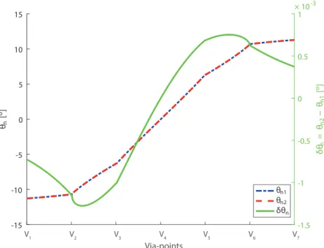
2.13 Moving-platform of the four-DoF planar under-constrained CDPR . 47 2.14 Natural inclinations θn1and θn2of the moving-platform . . . 52
2.15 Rotation angle θm1and θm2of the moving-platform . . . 53
2.16 Parasitic inclination θpof the moving-platform . . . 53
2.17 Parasitic inclination of the moving-platform along the test path . . . 54
2.18 Schematics of a planar suspended under-constrained CDPR . . . 55
2.19 Contour-plot and asymptote of φ as a function of ξ and ψ . . . 57
2.20 Contour-plot of φ as a function of ξ and ψ . . . 58
2.21 Contours of ρ over ξ and ψ . . . 59
2.22 Static workspace, SCDPC for different heights and the overall mass . 63 2.23 Feasible solutions and Pareto frontier of the optimization problem . . 68
2.24 Parallel graphs corresponding to the optimal solutions . . . 70
2.25 Design drawings of the moving-platform of the CDPC . . . 72
2.26 Assembly of the manufactured moving-platform of the CDPC . . . . 73
2.27 Equivalent architecture of the CREATOR prototype, [Bak+19] . . . . 73
2.28 computed torque control scheme . . . 76
2.29 Measurement of the inclination θnof the CDPC moving-platform with the accelerometer of a mobile phone . . . 77
2.30 Measured inclination of the CDPC moving-platform along a test path with three different heights . . . 78
3.1 Prototype of the CDPR with an embedded tilt-roll wrist . . . 82
3.2 Schematic of the CDPR with an embedded tilt-roll wrist . . . 83
3.3 Section-view of the moving-platform and tilt-roll wrist . . . 85
3.4 Schematic of the moving-platform with an embedded camera . . . . 86
3.5 Angles α, β, θ3and θ4 . . . 86
3.6 S1and S2for different orientations of the top-plate . . . 93
3.7 Twist feasible workspace of the manipulator with (ωx = ωy = ωz = ωα = ωβ = 0 rad.s−1) . . . 96
3.8 Twist feasible workspace of the manipulator with (−1.6 m.s−1 ≤ ˙px, ˙py, ˙pz ≤1.6 m.s−1& ωx = ωy= ωz = 0 rad.s−1) . . . 97
3.9 Top-view of the base frame and up-scaled moving-platform with the embedded tilt-roll wrist . . . 99
3.10 Workspace of the CDPR without (Left) and with (Right) an embedded tilt-roll wrist . . . 103
xv
3.11 Workspaces S1 and S2 associated with the optimum design of the
CDPR with an embedded tilt-roll wrist with two additional uni-actuated
cables . . . 104
3.12 Evolution of RS2 as function of pairs of decision variables . . . 105
3.13 Mechanical drawing of the tilt-roll wrist and the moving-platform, section-view(left) top-view (right) . . . 106
3.14 PID control scheme of the 3T2R manipulator . . . 106
3.15 Equivalent architecture of the manipulator . . . 107
3.16 Parameterization of test-trajectory 2 . . . 109
3.17 Schematic illustration of the inverse-geometric solutions of the tilt-roll wrist for a given pose of the top-plate related to test-trajectory 2. 111 3.18 Controller tracking error along the test-trajectory 2 . . . 112
3.19 Extracted laser dot trajectory during the second phase of the test-trajectory 2 . . . 113
3.20 Variation in the cable length during test-trajectory 2 . . . 113
3.21 Proportion of the cable-loop lengths variation due to the wrist rota-tions during the test-trajectory 2. . . 114
4.1 Design and prototyping process of the concept of CDPRs with an em-bedded parallel spherical wrist . . . 119
4.2 Architecture of the CDPR with an embedded parallel spherical wrist, in the framework of the CREATOR project. . . 120
4.3 The mobile platform with cables . . . 121
4.4 Parametrization of the parallel spherical wrist, [Pla+18] . . . 122
4.5 Representation of the applied wrench on a drum of a cale-loop . . . . 124
4.6 Orientation of the camera axis, y2with respect to F1 . . . 125
4.7 Exploded view of the parallel spherical wrist . . . 128
4.8 Top plate sub-assembly . . . 129
4.9 Carriage assembly. . . 129
4.10 Schematics of the assembly of cable-loops . . . 130
4.11 Top-plate of the 3T3R manipulator and anchor points . . . 132
4.12 Results of the optimization algorithm . . . 133
4.13 Control architecture of CREATOR . . . 134
5.1 Schematic of the proposed parallelogram cable system . . . 140
A.1 Initial architecture of the CREATOR demonstrator . . . 142
A.2 Architecture of the Reconfigurable CREATOR demonstrator . . . 142
A.3 Exploded view of the actuation unit . . . 143
A.4 Exploded CAD-view of the winch mechanism . . . 143
A.5 Assembly of the preliminary actuation and winch unit . . . 144
A.6 Reconfigurable actuation unit and winch mechanism . . . 145
A.7 Preliminary 3D printed eyelet, [Bak+19] . . . 145
A.8 Eyelet plate. . . 145
A.9 CAD design of a 2-DoF pulley . . . 146
B.1 Analysis of CMI for a given configuration of a CDPR . . . 148
B.3 WFW boundary of the first case study . . . 149
B.4 WFW boundary of the second case study . . . 150
B.5 Geometric description of a fully constrained CDPR . . . 152
B.6 A two-DOF point-mass planar cable-driven parallel robot driven by
three cables. . . 156
B.7 Required Twist Set (RTS) of the point-mass P and corresponding Re-quired Cable Velocity Sets for the three cables of the CDPR in a given
robot configuration . . . 158
B.8 Required cable velocity polytope and available cable velocity polytope 159
B.9 Maximum Required Cable Velocity (MRCV) of each cable through the
Cartesian space for the RTS shown in Fig. B.7b . . . 160
B.10 A feasible twist pose and an infeasible twist pose of the CDPR . . . . 161
B.11 TFW of the planar CDPR for four maximum cable velocity limits and
for the RTS shown in Fig. B.7b . . . 162
B.12 Planar and spacial CDPRs for analysis of TFW . . . 164
B.13 TFW of case study 1 calculated by CMI approach for different ˙li,max . 165
B.14 TFW of case study 1 calculated by cable velocity boundary approach 166
B.15 TFW of case study 2 calculated by different approaches for different ˙li,max . . . 167
xvii
List of Tables
1.1 Merits and demerits of Cable-Driven Parallel Robots (CDPRs) . . . . 3
2.1 Radius of the main components of the hoist mechanism . . . 25
2.2 Design parameters of the CDPC . . . 51
2.3 Design variables boundaries . . . 66
2.4 Input parameters of the optimization problem . . . 69
2.5 Boundary of optimal design variables and objective functions . . . . 69
2.6 Design parameters of CREATOR prototype . . . 75
3.1 Parameters of the CREATOR prototype . . . 94
3.2 Boundaries and optimum values of the design variables. . . 100
3.3 Given design parameters . . . 101
xix
Acronyms and Abbreviations
CDPR Cable-Driven Parallel Robot
WFW Wrench-Feasible Workspace
TFW Twist-Feasible Workspace
SW Static Workspace
DoF Degree-of-Freedom
CoM Center of Mass
RCVS Required Cable Velocity Set
ACVS Available Cable Velocity Set
RTS Required Twist Set
ATS Available Twist Set
PSW Parallel Spherical Wrist
TRW Tilt-Roll Wrist
CDPC Cable-Driven Parallel Crane
CDPR\TRW Cable-Driven Parallel Robot with an Embedded Tilt-Roll
Wrist
CDPR\PSW Cable-Driven Parallel Robot with an Embedded Parallel
Spherical Wrist
CREATOR robot parallèle à Câbles ayant un gRand Espace de trAvail
en Translation et en ORientation)
HSM Hyperplane Shifting Method
1
Chapter 1
Introduction
Contents
1.1 Cable-Driven Parallel Robots (CDPRs) . . . 2
1.2 Applications . . . 3
1.3 Classification . . . 6
1.4 CDPRs with Large Translation Workspaces . . . 9
1.5 CDPRs with Large Orientation Workspaces . . . 10
1.6 Hybrid CDPRs. . . 11
1.7 CREATOR Project . . . 15
1.8 Contribution and Thesis Organization . . . 15
1.8.1 A Planar Hybrid Cable-Driven Parallel Crane . . . 15
1.8.2 Hybrid CDPR with an Embedded Tilt-Roll Wrist . . . 16
1.8.3 Hybrid CDPR with an Embedded Parallel Spherical Wrist . . 17
1.8.4 Twist Feasible Workspace . . . 17
Parallel robots are closed-loop mechanisms with high performance in terms of accuracy, rigidity and payload capabilities. They have been used in a large variety of applications, like, astronomy and flight simulators. They have drawn many in-terests towards the machine-tool industry [Mer06]. Parallel architectures were origi-nally proposed in the context of tire-testing machines and flight simulators [Gou57],
[Ste65]. Since then, they have been used in other applications requiring
manipula-tion of heavy loads with high acceleramanipula-tions such as vehicle driving simulators or a
riding simulator developed for the french national riding School [KD04].
Parallel manipulators share the payload on theirs limbs leading to a high pay-load capacity. Moreover, due to the traction-compression in the joints of parallel robots, a better positioning precision is obtained by parallel manipulator compared to serial manipulators. Parallel manipulators have attracted the attention of the re-searchers and manufacturers due to their outperforming characteristics in terms of stiffness, precision, dynamic performance, compared to serial robots. Parallel robots include variety of industrial applications, such as flight simulation, machining and medical robotics.
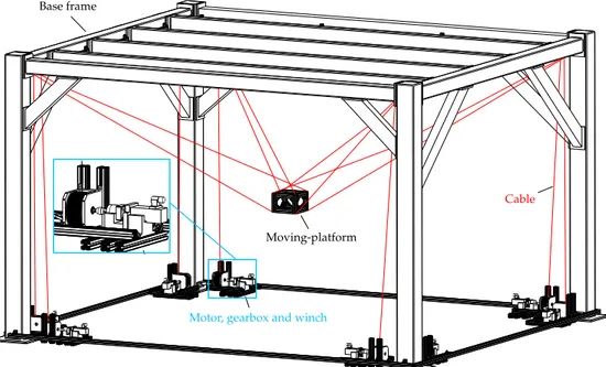
Motor, gearbox and winch
Moving-platform
Cable
Base frame
Figure 1.1: Architecture of the cable-driven parallel robot, developed in the framework of the CREATOR project, LS2N, Nantes, France
1.1
Cable-Driven Parallel Robots (CDPRs)
Cable-Driven Parallel Robots (CDPRs) also noted as wire-driven robots are parallel manipulators with flexible cables instead of rigid links. A CDPR consists in a base frame, a Platform and a set of cables connecting in parallel the moving-platform to the base frame. The pose of the moving-moving-platform is determined based on the geometry of the exit-points as well as the anchor-points. The former is the con-nection between a cable and a point on the fixed frame and the latter is the connec-tion point between a cable and the moving-platform. Active cable lengths, i.e., the distance between exit and anchor points are adjusted by coiling the cables on
motor-ized winches. A schematic of the architecture of CDPRs is presented in Fig.1.1.
CD-PRs are well-known for their advantages over the classical parallel robots in terms of large workspace, reconfigurability, large payload capacity and high dynamic per-formance. Nevertheless, one of the main shortcomings of the CDPRs is their limited orientation workspace. The latter drawback is mainly due to cable interferences and collisions between cables and their surrounding environment.
The interest of researchers has been drawn toward CDPRs because of their nov-elty and open issues originated from the nature of cables. Despite of classical paral-lel robots, CDPRs consist in uni-directional force transmission limbs.
In spite of all the mentioned advantages of CDPRs, we can note the common drawbacks and challenges that should be dealt with. One of the main drawbacks of the CDPRs arises from the actuation of cables. Cables can only pull but not to push, as a result, the control of the robot is more complicated than the conventional parallel robots. Another challenge can be considered as lower stiffness due to nature of cables resulting to the instability and vibration of the moving-platform. The main characteristics of CDPRs are pointed in Table1.1.
1.2. Applications 3
Table 1.1:Merits and demerits of Cable-Driven Parallel Robots (CDPRs)
Merits Demerits
• Large translational Workspace • Limited orientation workspace
• Inexpensive • Repercussions due to cable
rup-tures
• Low inertia of the moving
plat-form • Cable interferences
• Reconfigurability and
transporta-bility • Cable elongation and deformation
• Remote actuation of the
moving-platform • Poor accuracy
• Energy efficiency
• High payload-to-weight ratio
1.2
Applications
Due to the distinct merits of the CDPRs, they are used in variety of tasks from in-dustrial to entertainment applications. NIST RoboCrane is one of the earliest CDPRs designed based on the idea of the Stewart platform. NIST RoboCrane is a suspended crane by six cables capable of performing tasks within its large workspace with six (Degree of Freedom) DoFs. Its example applications are mentioned as flexible-structure mobility, heavy flexible-structure and equipment handling [Bos+94;BJB99].
One distinct characteristic of CDPRs was demonstrated by FAST (Five-Hundred Meter Aperture Spherical Radio Telescope) where its moving-platform contains the
receiver cabin of a large reflector dish as shown in Fig. 1.2. FAST is a large-scale
CDPR with a suspended moving-platform while encountering two main challenges
in terms of inverse kinematics and the stiffness due to sag in the cables [Dua99;
KZW06;Dua+09;WR15].
Skycam is one of the most popular CDPRs used in sport broadcasting. Skycam was patented in 2005 as a three dimensional moving camera assembly with an infor-mational cover housing. This CDPR consists of a cable driven trolley and a camera platform similar to Stewart platform and suspended by four cables. One instance of the application of skycam is presented in Fig.1.3.
CDPRs have also engaged in entertainment and art. Thrill ride CDPR, i.e, an amusement park ride with cable-suspended vehicle is a patented concept shown in
Fig.1.4by Disney [Pot18; CN12]. Two CDPRs each suspended by eight cables were
simultaneously flying over head of visitors for entertainment and artistic purposes
at EXPO 2015 in Milan as shown in Fig. 1.5. The safety, robustness and technical
feasibility of the robots were demonstrated by showing its performance in front of
Figure 1.2: FAST spherical radio tele-scope [Dua99;KZW06;Dua+09;WR15]
Figure 1.3: Skycam camera system at NRG Stadium in Texas [Skya;Skyb]
Figure 1.4: Amusement park ride with cable-suspended vehicle, [Pot18;CN12]
Figure 1.5: CDPRs flying over the heads of the visitors at the EXPO 2015, [Tem+15]
Several interesting CDPR prototypes and demonstrations employed in the med-ical and rehabilitation field. A Light-weight exoskeleton, namely, CAREX was
pro-posed by Ying Mao et al. as shown in Fig. 1.6. This prototype is a rehabilitation
and human movement training CDPR designed for upper arm movement training
[Mao+14]. String-Man prototype is presented in [SB04]. The prototype is an
ad-vanced gait rehabilitation robot aiming at weight bearing, balancing and posture
control in 6-DoFs as shown in Fig.1.7. Another application of CDPRs in the field of
medical science and specialized in surgical robotics is demonstrated in Fig.1.8. The Raven-II system with a grasper which has 4 DoF (wrist roll, wrist yaw, and finger pitch times two fingers) actuated by cables.
Intralogistics, handling and sorting of goods at industrial level, are suitable ap-plication for CDPRs due to their advantages in terms of high payload capacity, large workspace and high dynamic performance. The prototype of FALCON-7 is the
earliest CDPR with high-speed pick-and-place ability illustrated in Fig. 1.9. The
moving-platform of FALCON-7 (FAst Load Conveyance robot with 7 wires) obtains ultra-high speed and more than 40 times of the gravitational acceleration with
com-mercial actuators [Li94; KKW00b; KK15]. A lightweight and fast CDPR, namely,
1.2. Applications 5
Figure 1.6: Cables routed through the cuffs and controlled in tension in CAR-TEX CDPR for arm training and rehabili-tation purposes [Mao+14]
Figure 1.7: String-Man CDPR for gait rehabilitation and posture control [SB04; Pot18]
logistic by Bruckmann et al. in [Bru+13b; Bru+13a; LBS13]. Moreover, a mobile
CDPR, named FASTKIT, with multiple mobile bases for logistics was introduced in
[Ras+18;Ped+19] as shown in Fig.1.11. The prototype was developed to be a faster
and more versatile alternative solution for industrial logistics.
CDPRs have also been employed as measurements and calibration systems. In
[Jeo+98; JKK99] a CDPR was introduced for measuring the pose of a robot
end-effector. The position and orientation of the robot are computed through solving forward kinematic equations for the cable lengths of the CDPR. Similarly, IPAnema 2 (shown in Fig.1.12) estimates the pose of the end-effector of an industrial robot based
on the measured cable lengths through optical absolute encoders [Pot+13].
Further-more, Pott in [Pot10] developed an algorithm for real-time forward kinematics of
CDPRs, which was employed for IPAnema 2.
A modular hybrid CDPR consists of standalone modules, an end-effector and a rover with a robotic manipulator. This architecture enables the manipulator for per-forming inspection and space exploration on celestial bodies as studied in [SGW16].
One application of the proposed manipulator is illustrated in Fig. 1.13. Moreover,
comprehensive introduction to the history and development of CDPRs and their latest applications are presented in the literature, e.g., [Qia+18;Pot18].
Figure 1.8: The Raven II robot of UW EE’s BioRobotics is an open-source platform for surgi-cal robotics research [Han+12;Lab]
Figure 1.9: High-speed pick-and-place FALCON prototype [Li94;
KKW00b;KK15]
Figure 1.10: CABLAR CDPR as a large-scale storage retrieval machine [Bru+13b; Bru+13a; LBS13]
1.3
Classification
CDPRs can be categorized into different groups based on their geometry, DoF, func-tion, actuafunc-tion, motion pattern and etc. In the following some CDPRs are classified based on their geometry.
A CDPR is kinematically categorized into under-constrained, fully-constrained
and over-constrained in [Pot18;Min94]. By assuming number of cables denoted by
mand the number of the DoF of the moving-platform as n, we proceed to distinguish
CDPRs as follow:
In Under-constrained CDPRs, the number of cables is less than DoF of the
1.3. Classification 7
Figure 1.11:A mobile cable-driven parallel robot for logistics [Ped+19]
some DoFs cannot be controlled by the cables and the moving-platform can go through stable or unstable equilibrium state in presence of applied wrench.
Fully-constrained CDPRs have controllable n-DoF of the moving- platform and
the force equilibrium is dependent on the external wrench applied onto the moving-platform. Since this group of CDPRs are dependent on the external wrench, they can be classified as Incompletely Restrained Positioning Mechanism (IRPM) according to Ming et al. in [Min94]. In fully-constrained CDPRs like DeltaBot [Beh+03], NeReBot
[Ros+05], number of cable is equal to the number of Dof, i.e., n = m.
The moving-platform of a CDPR manipulator is denoted as over-constrained while
m > n. In this family of CDPRs they are called Completely/Over Redundantly
Restrained Positioning Mechanisms (CRPM/RRPM). They are not kinematically re-dundant since they have one solution to their inverse geometric problem but redun-dant in actuation, e.g. CaTraSys [OCP10] and Cogiro [LG13]. Therefore, generally, there exist more than one solution to their static equilibrium and the domain of the solutions depends on the admissible cable tensions. A CDPR depending on its moving-platform pose and applied external wrench may undergo slack cable(s).
Furthermore, CDPRs can be classified based on their cable arrangement. A
Figure 1.12: IPAnema 2 measurement device: Cable sensor based 6-DoF pose measurement system applied to measure the pose of an industrial robot, [Pot+13]
1.4. CDPRs with Large Translation Workspaces 9
moving-platform, e.g, Skycam [Con85]. In this configuration, the gravity force
ex-erted on the moving-platform can be assumed as a virtual cable with a constant ten-sion along the gravity direction and the static equilibrium is dependent on the mass of the moving-platform. Suspended CDPRs have advantages over non-suspended ones in terms of interference of cables with objects and their environment. Moreover, the suspended CDPRs over-perform non-suspended ones regarding maximum ad-missible payload. On the other hand, in non-suspended configurations, the moving-platform obtains a better stiffness and dynamic performance and as a consequence, less instability and vibration of the moving-platform.
1.4
CDPRs with Large Translation Workspaces
CDPRs are well-known for their large translation workspace thanks to the flexible nature of cables. Few CDPRs with drastically large translation workspace are enu-merated in the previous section, e.g., FAST with a suspended moving-platform over 520 meter diameter telescope aperture and Skycam with a suspended camera and a stadium-sized translation workspace.
Geometry selection and cable arrangement are crucial parameters involved in
the workspace size of CDPRs. M. Gouttefarde et al. in [Gou+15b] developed a
new suspended CDPR geometry with large workspace to footprint ratio. The study is carried out in the context of CoGiRo project with the demonstrator shown in
Fig. 1.14. CableRobot is a large scale motion simulator with a workspace size of
100 cubic meter introduced in [Mie+16]. The CableRobot simulator developed at
the Max Planck institute is one of the first CDPRs capable of human transport and
motion simulation as shown in Fig.1.15
Figure 1.14: Prototype of the CDPR with large translation worksapce in the con-text of the CoGiRo project, [Gou+15b]
Figure 1.15: The CableRobot motion simulator with a large translation workspace, [Mie+16]
Reconfigurability, one of the main features of CDPRs, can be used to extend their
workspace. In [Gag+16b], the authors studied the importance of the geometry
deter-mination of the CDPRs with respect to the sizes of their workspaces. These authors proposed a methodology for the planning reconfiguration of CDPRs from a discrete
set of possible exit-points unlike conventional CDPRs. Figure1.16demonstrates the
Figure 1.16:Schematic of the concept of a reconfigurable CDPR in [Gag+16b]
1.5
CDPRs with Large Orientation Workspaces
There are varieties of tasks and applications requiring CDPRs with large orienta-tion workspace, e.g., camera surveillance, inspecorienta-tion, 3D object scanning, entertain-ment. Despite their large translation workspaces, CDPRs are generally unable to provide large amplitudes of rotation of their moving-platform due to collisions be-tween their moving parts. For instance, the large cable-suspended parallel robot of
the project CoGiRo in [Gou+15b], can only provide a limitted range of orientation,
i.e.,±40◦about its horizontal axes and 105◦(−70◦to+ 35◦) about its vertical axis. In
general, the workspace of parallel robots can be increased by combining them with other parallel or serial mechanisms and constructing hybrid mechanisms. To the best of the authors’ knowledge, there is but a limited number of research-works
ad-dressing the question of extending the rotation workspaces of CDPRs. In [Pla+18],
a parallel spherical wrist was introduced into the design of a CDPR to obtain large rotation and translation workspaces. The authors showed that the workspace of CDPRs can be enlarged by combining the advantages of the parallel spherical wrist in terms of rotation amplitudes with those of CDPRs in terms of large translation
workspace. Miermeister et al. in [MP15; Rei+19] introduced a new hybrid design
for CDPRs with coupled platforms while enabling them for an endless rotatable
axis. In Fig. 1.17a a moving-platform with thirteen as the minimal number of
re-quired cables for a spatial CDPR with the geometry of a crankshaft, is proposed to achieve an endless rotatable axis. Furthermore, a planar manipulator with eight
cables was presented with an unlimited orientation DoF as depicted in Fig. 1.17b.
Moreover, a cable structure for haptic interface and cable robots with large
orienta-tion workspace were patented by Gosselin in [Gos07]. The mechanism is claimed to
1.6. Hybrid CDPRs 11
(a)A spatial CDPR with a crankshaft geometry (b)A planar CDPR with two platforms
Figure 1.17:Concepts of CDPRs each with an unlimited rotatable axis [MP15;Rei+19]
1.6
Hybrid CDPRs
Serial manipulators exhibit characteristics that are often opposite to those of paral-lel manipulators. Serial robots have a large workspace while that of paralparal-lel ma-nipulators is usually smaller and more complex. In general, the payload, speed, acceleration, stiffness and accuracy of serial robots are lower than those of parallel robots [PD14]. The combination of a parallel and a serial manipulator or at least two parallel manipulators forms a hybrid manipulator. The goal is generally to exploit the advantages of their parallel and serial kinematic chains to improve their overall performance in given tasks. They are generally designed to extend the workspaces of parallel robots.
Macro-micro manipulators are made up of a large (macro) robot carrying a small (micro) robot with high performance in order to improve the functionality of the
overall manipulator [SHH93]. Macro-micro manipulators are often known as
hy-brid robots. A micro manipulator is called active wrist on condition that its
orienta-tion DoFs replace those of the macro robot [Mer06]. This architecture enhances the
overall manipulator workspace size while imposing mass and size constraints on the manipulator.
Similar to hybrid parallel robots, the combination of CDPRs with serial and
par-allel mechanisms form hybrid CDPRs. In [BG15], a large-scale cable-suspended 3D
foam printer was introduced. The proposed manipulator is an hybrid robot, i.e., a serial end-effector (foam gun mechanism with one-DoF) connected to the
moving-platform of the CDPR as shown in Fig.1.18. This hybrid CDPR employs
motoriza-tion on the moving-platform and as a consequence on-board motor requires cable routing, which increases the chance of interferences with the CDPR cables. CAT4 is
a hybrid cable actuated truss with 4-DoF presented in [KN02]. This hybrid
manip-ulator, namely, a combination of two parallel kinematic chains, consists in a central mechanism while its end-effector is constrained to three translational and one rota-tional motions as depicted in Fig.1.19. In [Che+13], the authors presented a hybrid
(parallel-serial kinematic structure) CDPR as a 7-DoF humanoid arm. Figure 1.20
illustrates the hybrid robot with a passive spherical wrist.
Figure 1.18:Hybrid cable suspended 3D foam printer, [BG15]
The synthesis of CDPRs with complementary mechanisms to design hybrid CD-PRs can be realized through bi-actuated cables, i.e, cable-loops. One advantage of cable-driven parallel robots that has not yet been fully exploited is the possibility of using the cables to transmit power directly from motor fixed to the frame to the moving-platform. This power can then be used to actuate a tool or to control
ad-ditional degrees of freedom such as rotations over wide ranges [Pla+18], for
exam-ple. There has been a few research conducted on the modeling of cable-loops. In
[Nag+12], a cable-loop is denoted as a Double Actuator Module (DAM). Moreover,
cable-loops were developed and studied in context of different types of manipula-tors. Antagonistic cable pairs accompanied with multi-radius pulleys are presented
in [RSBT17] to consolidate the actuation of multiple links of a snake robot.
Na-gai K. et al. in [Nag+11] proposed a cable-loop-powered mechanism for producing
motions with high acceleration of the moving-platform in the global frame by the total force of cable-loop exerted on the moving platform. Besides, it leads to precise motion of the end-effector in its local frame by induced moment of cable-loops. A
hybrid CDPR employing cable-loops is presented in [LDN16]. The proposed
con-cept of the hybrid robot by employing seven cable-loops (and fourteen actuators) for producing fast and precise motions is shown in Fig1.21.
A cable-loop forms a cable circuit by connecting two actuators while passing through two anchor points on the moving-platform and coiling about a drum as
shown in Fig. 1.21. This arrangement of cables is used for two distinct purposes.
The former is to locate the moving-platform within its workspace and the latter is to actuate the drum. In other words, two motions can be induced by the cable-loop depending on the relative rotation of its two actuators. The first one is the
1.6. Hybrid CDPRs 13
Figure 1.19:CAT4, 4-DOF cable actuated parallel manipulator, [KN02]
displacement of the moving-platform and extension of the loop for identical inputs of the two motors. The second motion is circulation of the loop which results into rotation of the drum, when the two actuators rotate in opposite directions. This convention leads to a very large amplitude of rotation of the drum. The cable-loop system provides a vast orientation of its drum, which can be employed whether for enlarging the orientation workspace or for actuating an embedded mechanism on the body of the moving-platform.
Figure 1.21:Concept of a hybrid CDPR with remote actuation of the end-effector, [LDN16]
Khakpour et al. ([KB14], [KBT14] and [KBT15]) introduced differentially driven cable parallel robots using cable differentials. This idea focuses on replacing ac-tuated cables with two or more cables while connected to one actuator through a differential mechanism. They proved that, by replacing single-actuated cables with differential cables the static and wrench feasible workspaces of CDPRs can be ex-tended while keeping the same number of actuators. The schematic of the proposed
deferentially driven planar CDPR is presented in Fig.1.22. Similarly, many
tendon-driven robotic hands with hybrid structure have employed differential mechanisms
for power transmission. The authors in [BG04;BG06] address kinetostatic and force
analysis of tendon-driven mechanisms. In [OHK09], Ozawa et al. enumerate
differ-ent types of tendon-driven mechanisms, namely Tendon-Controllable mechanisms (TC) capable of generating any joint torque, under-actuated Hybrid Tendon-driven mechanisms (HT) with unique solutions to their associated inverse kinematic prob-lems and finally Under-Tendon driven mechanisms (UT) are the under-actuated systems with multiple solutions for their inverse kinematic problems as shown in Fig.1.23
1.7. CREATOR Project 15
Figure 1.22:A planar CDPR with a point mass moving-platform with (a) two single-actuated cables (b) a differentially driven cable, [KBT14]
Figure 1.23: Tendon-driven mecha-nism types, (a) TC (b) HT (c) UT, [OHK09]
1.7
CREATOR Project
The CREATOR (robot parallèle à Câbles ayant un gRand Espace de trAvail en Trans-lation et en ORientation) project aimed to design a hybrid robot with a large workspace in translation and orientation. The CREATOR project, funded by Atlanstic 2020
pro-gramme (link 1), started in 2016 and ended in 2020. The task coordination of the
project in illustrated in Fig.1.24.
The robot is hybrid because it combines advantages of a CDPR in terms of a large translation workspace and pros of spherical wrists with large rotational amplitudes to form CDPRs with large translation and orientation workspaces.
1.8
Contribution and Thesis Organization
Generally, CDPRs have large translation workspace, however, most of them pro-vide only limited rotations of the moving-platform due to the collision between the cables. The objective of this research-work is to design hybrid robots with both large translation and orientation workspaces. Those robots are hybrid because they combine the advantages of cable-driven parallel robots in terms of large translation workspace and the pros of the parallel spherical wrists in terms of large rotational amplitudes. The main contributions of the thesis are highlighted in the following.
1.8.1 A Planar Hybrid Cable-Driven Parallel Crane
This manuscript introduces the concept of a new planar Cable-Driven Parallel Crane (CDPC) for lifting and carrying payloads with a moving hoist mechanism connected in parallel to the ceiling. In the context of our research work. The main objective of this manipulator is to provide underlying foundation for realizing hybrid CDPRs using cable loops. Therefore, the simplest form of a hybrid robot, i.e., one-DoF ar-ticulated moving-platform, is considered for further investigation regarding hybrid CDPRs with large translation and orientation workspaces. In contrast to bridge-crane, CDPC is inexpensive and practicable for diverse tasks with simple assembly setup. The hoist mechanism is an under-constrained moving-platform articulated
Modeling and Valibration of Hybrid robots
Concept of Parallel Spherical Wrist
Task Coordination of the Project
Concept of the Cable-Driven Parallel Robot
Trajectory Generation, Control and Simulation of Hybrid Robots
Prototype and Experimental Validation
Figure 1.24:Task coordination of the CREATOR project
through a bi-actuated cable circuit, namely, a cable-loop. The hoist is connected to a suspended moving-platform with four DoF. The power is transmitted directly from the motors, mounted to the ground, to the hoist through the cable loop. There-fore, the dynamic performance of the robot is increased due to lower inertia of the moving-platform. However, the moving-platform undergoes some parasitic incli-nations because of the cable-loop for remote actuation of the moving-platform in the CDPC. In the second chapter, we investigate these unwanted rotational motions of the moving-platform. Parasitic inclination as a property of lower mobility parallel mechanisms leads to inaccuracy in positioning. Finally, those parasitic inclinations are modeled and assessed for the mechanism at hand.
This manuscript investigates the parasitic inclination and its effect on the sys-tem. The workspace of the proposed CDPC is studied in terms of static and kine-matic performances. Moreover, the kinetostatic model, optimum design, control
and demonstration of the CDPC are presented in Chapter2.
1.8.2 Hybrid CDPR with an Embedded Tilt-Roll Wrist
The development of a novel CDPR with an embedded tilt-roll wrist is addressed in the framework of the thesis. The manipulator consists of a tilt-roll wrist mounted on the moving-platform of a suspended CDPR. The embedded wrist provides large amplitudes of tilt and roll rotations and a large translational workspace obtained by the CDPR. This manipulator is suitable for tasks requiring large rotation and translation workspaces like tomography scanning, camera-orienting devices and vi-sual surveillance. The moving-platform is an eight-DoF articulated mechanism with
1.8. Contribution and Thesis Organization 17 large translation and orientation workspaces and it is suspended from a fixed frame by six cables. The manipulator employs two bi-actuated cables, i.e., cable-loops to transmit the power from motors fixed on the ground to the tilt-roll wrist. Therefore, the manipulator achieves better dynamic performances due to a lower inertia of its moving-platform. Furthermore, the kinetostatic model, optimum design, configu-ration, prototyping, workspace analysis and control of the proposed CDPR with an embedded tilt-roll wrist are elaborated in Chapter3.
1.8.3 Hybrid CDPR with an Embedded Parallel Spherical Wrist
The concept of a hybrid CDPR with an embedded parallel spherical wrist is studied and implemented in the context of the manuscript. This manipulator employs the similar kinematic architecture as the CDPR with an embedded tilt-roll wrist but with an additional DoF. The proposed manipulator has nine-DoF while its parallel spher-ical wrist provides three drastspher-ically large orientations DoF of its end-effector beside six DoF of the moving-platform. The hybrid manipulator employs three cable-loops for remote actuation of its active wrist. The kinetostatic model, static workspace, design and experimental demonstration of the proposed manipulator are detailed in Chapter4.
1.8.4 Twist Feasible Workspace
Although several papers addressed the wrench capabilities of cable-driven parallel robots, few have tackled the dual question of their twist capabilities. In the context of this thesis, these twist capabilities are evaluated by means of the specific concept of twist feasibility, which was defined in [Gag+16b]. A CDPR posture is called twist-feasible if all the twists (point-velocity and angular-velocity combinations), within a given set, can be produced at the CDPR mobile-platform, within given actuator speed limits. Two problems are solved in this manuscript: (1) determining the set of required cable winding speeds at the CDPR winches being given a prescribed set of required mobile platform twists; and (2) determining the set of available twists at the CDPR mobile platform from the available cable winding speeds. Then, twist feasibility is investigated for the proposed hybrid CDPRs.
19
Chapter 2
Planar Cable-Driven Parallel Robot
with an Embedded Crane
Contents
2.1 Modeling . . . 22
2.1.1 Cable Loop (bi-actuated cable) . . . 22
2.1.2 Kinetostatic Model of the CDPC . . . 22
2.1.3 Elasto-static Model of the CDPC . . . 30
2.2 Analysis . . . 32
2.2.1 Twist Feasible Workspace (TFW) . . . 34
2.2.2 Wrench Feasible Workspace (WFW) . . . 38
2.2.3 Parasitic Inclinations . . . 42
2.2.4 Required Height of the Ceiling for a Given Payload . . . 59
2.3 Optimum Design of the CDPC . . . 62
2.4 Prototyping and Experimentation. . . 71
2.4.1 CREATOR Demonstrator . . . 71
2.4.2 Control . . . 74
2.4.3 Measurement of the Natural Inclinations . . . 76
2.5 Summary of the Chapter . . . 77
The motivation of this chapter is to analyze, build and prototype a simple hy-brid manipulator with large translational and rotational workspace. The strategy followed for realizing hybrid CDPRs with large orientation workspaces is to com-bine manipulators with large orientation workspaces with CDPRs with large trans-lational workspace. This chapter investigates an innovative approach for the con-struction of such hybrid robots. The basis of the manuscript i.e., CDPRs with large translation and orientation workspace is formed by studying and realizing one of the earliest type of hybrid CDPRs through remote actuation of the moving-platform through cable-loops. To the best of the author’s knowledge, there have been a few research proposing the idea of the remote actuation for CDPRs without practical im-plementation. A cable-loop or bi-actuated cable circuit is detailed in the context of this chapter.
In order to design the simplest form of a hybrid CDPR compatible with one cable-loop, we introduce the concept of a new planar Cable-Driven Parallel Crane (CDPC) with an embedded hoist mechanism within the moving-platform of the
CDPR. The proposed hoist mechanism is embedded into the CDPR and has one
DoF. Figure 2.1 shows the prototype of the proposed manipulator consisting of a
moving-platform with an embedded hoist mechanism, two cables (shown in red) which connect the moving-platform to the actuators and a third cable (shown in yellow) which connects the hoist to a payload and adjusts its height. The target applications of the proposed hybrid robot is lifting and carrying payloads indoors with a moving hoist mechanism connected in parallel to the ceiling. The proposed concept of the CDPC does not require its moving-platform to approach the payload. This design improves the CDPR capabilities for carrying payloads while reducing interferences between cables and objects on the ground. The concept of embedding the hoist into the moving-platform is sensible as long as the hoist mechanism does not require actuation on the moving-platform. Actuators on the moving-platform lead to lower-level dynamic performance due to the higher inertia and interference between motor wires and cables of the CDPR. The issue is overcome by employing a cable loop in order to articulate the moving-platform remotely.
Nowadays, overhead cranes or bridge-cranes are widely used in industry. They usually consist in runways fixed to a ceiling which accommodates a hoist mecha-nism for lifting or lowering payloads throughout its workspace. They are appli-cable for heavy-payload tasks. However, the bridge-cranes have some drawbacks that reduce their utilization, i.e., they are bulky, expensive and should adapt to the structure of the buildings. In contrast to bridge-crane, the CDPC is inexpensive and practicable for diverse tasks with simple assembly setup. On the other hand, CDPRs may seem sound alternatives for bridge cranes as they can overcome the above-mentioned issues. A CDPR consists of a base frame, a moving-platform and a set of cables connecting in parallel the moving-platform to the base frame. CD-PRs have some advantages over bridge cranes. Indeed, they are easy to reconfigure
[Gag+16c], easy to assemble and comparatively inexpensive. Nevertheless, they
suffer from cable interferences with the surrounding environment and requires a mounting structure. Therefore with these advantages and drawbacks in mind, we hypothesize that in same situations the capabilities of the bridge cranes can be ex-tended by exploiting the advantageous features of CDPRs.
The hoist mechanism is an under-constrained moving-platform actuated through a bi-actuated cable circuit, namely, a cable loop. The hoist is connected to a sus-pended moving-platform with four degrees of freedom. The power is transmitted directly from the motors fixed on frames to the hoist through the cable loop. There-fore, the dynamic performance of the manipulator is increased due to lower inertia of the moving-platform.
Overall, this chapter is divided into six sections. Concept and design of the CDPC with an under-constrained mobile hoist, the cable-loop model, kinetostatic model and following the latter models the elasto-static of the manipulator are
pre-sented in Sec.2.1. The analysis of the CDPC in terms of the workspace and parasitic
inclinations is carried out in Section 2.2. Section 2.3 studies the optimum design
of the manipulator. In addition, the validation of the proposed concept is realized
in Sec. 2.4. Finally, conclusions are drawn and future work is presented in the last
Chapter 2. Planar CDPR with an Embedded Crane 21 Uni-actuated cable Uni-actuated cable Uni-actuated cable Bi-actuated cable Hoist cable Moving-platform Payload Obstacle Front-view Side-view Hoist Mechanism
2.1
Modeling
This section deals with the model of a simple CDPR with an embedded hoist mech-anism and its remote actuation through a cable-loop. Therefore, the cable-loop is introduced as well as kinetostatic and elastostatic models of the hybrid robot.
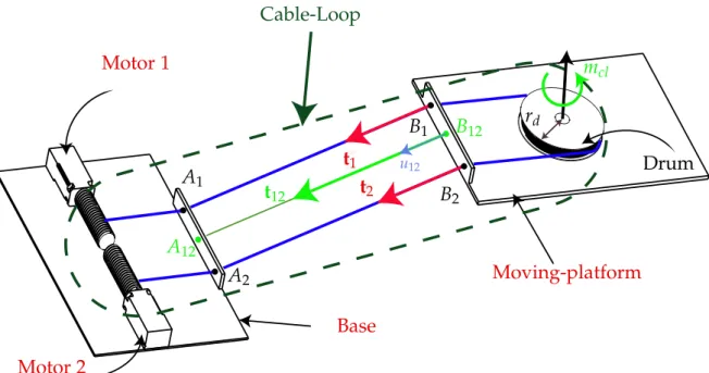
2.1.1 Cable Loop (bi-actuated cable)
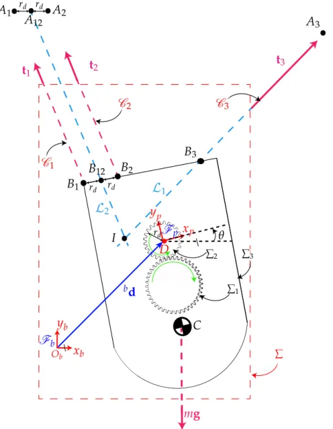
In Fig.2.2, a schematic represents a simplified form of a cable-loop system actuated by two motors while passing through exit-points, namely, A1, A2, and anchor-points,
namely, B1, B2. The cable-loop is coiled up around a drum on the moving-platform.
The cable-loop drum then acquires one rotational DoF with respect to the moving-platform used to actuate a tool or to control additional degrees of freedom such as rotations over wide ranges.
For the sake of the simplicity in modeling, one virtual uni-actuated cables can
substitute cable-loops. The latter virtual cable replace the cable-loop with A12 and
B12, as their exit point and anchor point, respectively. As long as the
moving-platform is far from points A1 and A2, then A1B1and A2B2can be assumed parallel and the virtual cable model replaces the cable-loop. The main geometrical charac-teristic of the manipulator is expressed as points Ai and Bi, which stand for the ith exit point and anchor point, respectively. ai = [aix, aiy]T, b
i = [bix, biy]T are the
respective Cartesian coordinate vectors of points Aiand Bi. The former point is the
location of ith pulley fixed to the ceiling and the latter point is ith cable associated anchor point located on the moving-platform.
a12 = (a1+ a2)/2 (2.1)
and,
b12 = (b1+ b2)/2 (2.2)
Hereafter, the effect of the cable loop tension onto the moving-platform is the force
passing through the midpoint B12 between B1 and B2 along the unit vector u12 of
segment A12B12,
t12 = t1+ t2 (2.3)
and a moment generated about rotational axis of the drum,
mcl = rd(t1−t2), (2.4)
where rdis the radius of the cable-loop drum.
2.1.2 Kinetostatic Model of the CDPC
This section deals with the kinetostatic modeling of a simple hybrid CDPR with an embedded one DoF mechanism. The proposed manipulator consists in an articu-lated platform actuated by three motors through two cables. The moving-platform accommodates a hoist mechanism, which is coupled with a cable loop. The cable loop has two distinct purposes. The first is to position the moving-platform and the second is to actuate the hoist. The hoist consists in a triple-stage reducer that
2.1. Modeling 23 Motor 1 Motor 2 Base Moving-platform t1 t2 Drum rd B1 B2 A1 A2 Cable-Loop B12 A12 mcl t12 u12
Figure 2.2:Representation of a simple cable-loop system for the moving-platform of a CDPR
increases the input torque generated by the cable loop and transmits it to a cable, Ch, that is wound onto a drum. Therefore, the relative height between the given pay-load and the moving-platform can be adjusted within the workspace of the CDPC. As the proposed application of the CDPC does not require its moving-platform to approach the payload, the risk of collision between objects on the ground with ca-bles of the manipulator is eliminated.
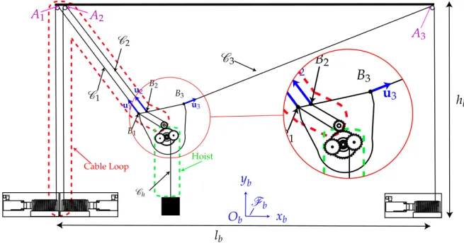
Architecture of the Manipulator
Here, we discuss the architecture of the CDPC. The overall manipulator consists in a base frame and a moving-platform connected in parallel by two actuated cables as
shown in Fig.2.3. The under-actuated moving-platform possesses four DoF within
a planar workspace. The moving-platform has two translational DoF in the xOy plane, one rotational DoF of axis normal to its translation plane. The actuation of the additional degree of freedom on the moving-platform is done through a cable loop and a drum, so that no motor needs to be mounted on the moving-platform for actuation of the end-effector.
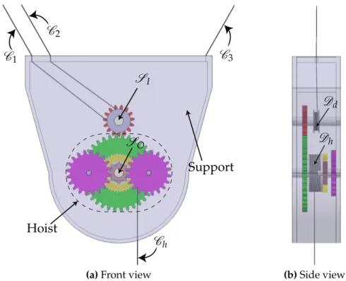
Figure2.4illustrates the overall schematic of the moving-platform of the CDPC.
The moving-platform is suspended by two cables, i.e., a cable loop (C1and C2) that
are actuated by two motors and another cable, C3, that connects the support of the
moving-platform to the third motor. The cables are directly connected to the sup-port of the moving-platform and the hoist mechanism is accommodated within the support. The hoist is outlined in the figure and its main task is to transmit the power from input shaft, SI, to the second shaft, SO. The input shaft is actuated by two mo-tors fixed to the ground and through the cable loop. The gear train, which is inspired from the one inlink1, increases the input torque and transfers it to S
O. The second
yb Ob xb A1 A2 A3 B1 B2 B3 C3 Fb lb hb u1 u2 u3 Cable Loop C1 C2 Hoist Ch
B
1B
2B
3 1u2
u
3Hoist
Figure 2.3:A four-DoF planar cable-driven parallel robot with a cable loop
shaft, transmits the power to the hoist drum, Dh, through a gear train. Consequently, Ch, is wound onto Dh. SO and Dhare concentric but are not in contact.
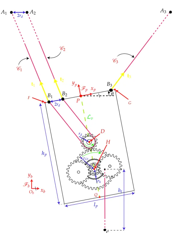
The cable loop connected to two actuators, which are shown in Fig.2.5, is coiled about, Ddto make the latter rotate about its own axis. The left side of this cable loop is denoted by C1 whereas its right side is denoted by C2. Another cable, identified
by C3, is connected to both the support of the articulated moving-platform and a
third actuator. The cable loop consists in two segments each with independent cable
tensions t1 and t2. Segment C1, is composed of the part of the cable-loop, which
connects the first motor to the drum through points A1and B1. The second segment
is denoted as C2 and connects the second motor to the drum through points A2
and B2. Two motions can be induced by the cable-loop depending on the relative
rotation of two actuators connected to the cable-loop. The first one is the translation of point D (the center of Ddshown in Fig.2.4) for identical inputs to the two motors and the second motion is a rotation about point C when the two actuators rotate in opposite directions.
Figure2.5shows the geometry of the platform of the CDPC. The
moving-platform frame, Fp, is located on the top of the moving-platform and belongs to its
vertical center-line, Lv. The overall dimension of the moving-platform is specified
by hpand lpthat denote the height and length of the moving-platform, respectively.
The radius of Dd is denoted as rd. Anchor-points B1 and B3 are located on the top corners of the moving-platform, so that the width of the moving-platform is com-puted as lp = b3x−b1x. Finally, the height of the moving-platform is denoted as hp.
2.1. Modeling 25 C1 C2 Support Hoist C3 Ch SI SO
(a)Front view
Dd
Dh
(b)Side view
Figure 2.4:Moving-platform of cable-driven parallel crane
Table 2.1: Radius of the main components of the hoist mechanism
Parameter rG1 rG2 rG3 rG4 rG5 rG6 rG7 rG8 rh
Value [mm] 17 42 12 25 25 12 12 21 20
Hoist mechanism
The hoist consists of a triple-stage reducer that increases the input torque generated by the cable loop and transmits it to a cable, Ch, that is wound onto a drum. There-fore, the relative height between the given payload and the moving-platform can be
adjusted within the workspace of the CDPC. The hoist is outlined in Fig.2.6and its
main task is to transmit the power from input shaft, Sd, to the second shaft, Sh. The input shaft is actuated by two motors fixed to the ground and through the cable-loop. The cable-loop rotates the input shaft (Sd), which leads to the rotation of the first gear, namely, G1and second gear G2. Next, the power is transmitted to the third gear G3through SO. It should be noted that the rotation of the SI does not affect
the rotation of Dhas the drum is connected to Shthrough a bearing. Then, gears G4 and G5rotate the left and right shafts Sr and Sl, respectively. The last gear, namely,
G8is actuated through G6and G7. The hoist drum, namely, Dhis attached to G8and
coils up Ch. Table2.1expresses the radii of the main parts of the hoist components,
![Figure 1.8: The Raven II robot of UW EE’s BioRobotics is an open-source platform for surgi- surgi-cal robotics research [Han+12; Lab]](https://thumb-eu.123doks.com/thumbv2/123doknet/7793928.260256/27.892.173.704.121.516/figure-raven-robot-biorobotics-source-platform-robotics-research.webp)
![Figure 1.12: IPAnema 2 measurement device: Cable sensor based 6-DoF pose measurement system applied to measure the pose of an industrial robot, [Pot+13]](https://thumb-eu.123doks.com/thumbv2/123doknet/7793928.260256/29.892.270.601.160.622/figure-ipanema-measurement-device-measurement-applied-measure-industrial.webp)
![Figure 1.21: Concept of a hybrid CDPR with remote actuation of the end-effector, [LDN16]](https://thumb-eu.123doks.com/thumbv2/123doknet/7793928.260256/35.892.222.648.299.681/figure-concept-hybrid-cdpr-remote-actuation-effector-ldn.webp)