Anthro Arm: The Design of a Seven Degree
Of Freedom Arm with Human Attributes
By
Adam Paul Leeb
SUBMITTED TO THE DEPARTMENT OF MECHANICAL ENGINEERING IN PARTIAL FULFILLMENT OF THE REQUIREMENTS FOR THE DEGREE OF
BACHELOR OF SCIENCE
AT THE
MASSACHUSETTS INSTITUTE OF TECHNOLOGY
JUNE 2007
@2007 Adam Leeb. All rights reserved.
The author hereby grants to MIT permission to reproduce and to distribute publicly paper and electronic copies of this thesis document in whole or in part in any medium now known or hereafter created.
Signature of Author:
Dep ment of Mechanical Engineering May 11, 2007
Certified by: H. Harry Asada
Professor of Mechanical Engineering Thesis Supervisor
Accepted by:
John H. Lienhard V Professor of Mechanical Engineering Chairman, Undergraduate Thesis Committee
MASSACHUSETTS INSTITUTE
OF TECHNOLOC3Y
ARCHIVES
JUN 2 12007
Anthro Arm: The Design of a Seven Degree
Of Freedom Arm with Human Attributes
By
Adam Paul Leeb
Submitted to the Department of Mechanical Engineering on May 11, 2007 in partial fulfillment of the requirements for the Degree of Bachelor of Science in Engineering as recommended
by the Department of Mechanical Engineering
ABSTRACT
Studying biological systems has given robotics researchers valuable insight into designing complex systems. This thesis explores one such application of a biomimetic robotic system designed around a human arm. The design of an anthropomorphic arm, an arm that is similar to that of a human's, requires deep insight into the kinematics and physiology of the biological system. Investigated here is the design and completion of an arm with 7 degrees of freedom and human-like range of motion in each joint. The comparison of actuation schemes and the determination of proper kinematics enable the
arm to be built at a low cost while maintaining high performance and similarity to the biological analog. Complex parts are built by dividing structures into interlocking 2d shapes that can easily be cut out using a waterjet and then welded together with high reliability. The resulting arm will become part of a bionic system when combined with an existing bionic hand platform that is being developed in the Intelligent Machines Laboratory at MIT. With a well thought out modular design, the system will be used as a test bed for future research involving data simplification and neurological control. The completion of the anthropomorphic arm reveals that is indeed feasible to use simple DC motors and quick fabrication techniques. The final result is a reliable, modularized, and anthropomorphic arm.
Thesis Supervisor: H. Harry Asada
TABLE OF CONTENTS
Introduction ... Literature Review ... Anthropom orphism ... 5 Design Evolution ... 7 Modularity ... 12Design for Fabrication ... ... 13
Actuation schem e... 14
Joint Design... 16 Shoulder ... 17 Elbow ... 19 Forearm ... 19 W rist ... 20 Controls...21 Further W ork... 22 Final Considerations ... ... 23 References ... 24
Appendix A: Rendered Draw ings ... ... 25
Appendix B: Various Arm configurations ... ... 26
Appendix C: Encoder Data Sheet... ... 27
Appendix D: Servo Specification Sheet ... ... 29
INTRODUCTION
In modern robotics research, very few if any systems have been shown to be as capable as their biological counterparts. A robotic leg or wing, for example, using conventional actuators is no match for a biological system of similar size. The question why this could be has pushed researchers into trying to mimic nature's design that has
evolved over millions of years. The common belief is that nature must have at least found an excellent solution, if not the best solution, for accomplishing difficult physical problems whether they are flapping a hummingbird wing or keeping a water strider afloat. Many researchers have now looked to biomimicry as the ultimate goal for robotic systems.
Another purpose for looking at nature, specifically human physiology is to try and mimic it for a robotic prosthesis. The purpose of creating a simulated system that can look, feel, and function like the real thing is a major area of focus for prosthesis research. In this paper, an anthropomorphic arm is developed and built such that it will be in turn used for research as a test bed for a human arm prosthetic. Coupled with an ongoing project
developing a biomimetic hand, these two components will form the backbone of a complete bionic system. Using the system in an experimental fashion during everyday tasks,
researchers in the lab will be able to reduce the complex kinematics of a 7 DOF arm into a simpler set of coordinate frames. This data simplification is a crucial step before
overcoming one of the largest problems in bionics: overcoming the limited amount of communication data between the brain and prosthesis.
LITERATURE REVIEW
In the area of Anthropomorphic robotics, there have been a string of noteworthy research efforts worth mentioning. While not meant to be a complete list, the following presents a snapshot of the field.
A new type of 3 DOF arm using tendon drive and fine motor control was developed to mimic biology's arm structure by Klug et al (1). The design proposed in their paper is a unique implementation of tendon drives with built in compliance. The problem that they were trying to eliminate is the need to use very rigid, large links to prevent arm flex. With
their link and actuation design, they can use less rigid links and also be more human friendly. Scaling from 3 to 7 DOF is clearly a challenge for them that has not yet been solved.
The work of Tondu et al on a seven DOF arm provided necessary anthropomorphic background needed for my research (2). In their project, they chose to use opposing air muscles as actuators. This arm served as the closest analog to the arm described in this thesis. There are also arms that have been designed with no intention of being built such as that proposed by Hollerbach in his paper, "Optimum Kinematic Design for a Seven Degree of Freedom Manipulator" (3). He describes a kinematic model that is supposed to be ideal for arrange seven degrees of freedom in the arm.
Research done on specifically designing an anthropomorphic shoulder was described in a paper by Lenarcie et al (4). Their design used a complicated, parallel
actuator setup with four translational joints attached to a plate. The plate can be moved in all the necessary axes by implementing the correct control method. This joint system was determined to be unfeasible to be used in the arm designed for this thesis due to
unnecessary complexity.
In "Cora: Anthropomorphic Robot Assistant" (5) the researchers used an off the shelf, light weight 7 DOF arm from Amtec. Their goal was to use the robot in conjunction with different sensors to look at interactions between the robot and its environment. Other researchers have also looked into the interaction with robots and their safety around people. This topic will become more important as controls and safety objectives are developed for the Anthro Arm. In work done by Tuijthof et al (6), it was shown that robot arms could be developed to be safe. The design that they tested was one in which the arm was intrinsically compliant all the time. They accomplished this through controls of the actuators and using pneumatic muscles for the mechanisms.
ANTHROPOMORPHISM
Developing an arm that will be used for prosthesis work forces the functional requirements of the design to be centered on human attributes, robustness, and
modularity. Human attributes such as size, weight and range of motion provided strict guidelines for the anthropomorphic arm. It was important to keep the profile of the arm in mind when designing the system. Many commercial systems look mostly like an arm but then have a motor hanging off the back of a joint. This was avoided almost entirely with the final arm design that was realized. The robustness of the overall system depended mostly
on the strength of the joints and mechanisms. Interlocking aluminum pieces that were then welded together forms the structure of the arm providing a rigid foundation for the joints and actuators. Modularity also helps with robustness because the arm was designed to be
used with interchangeable parts/systems. Not only are the gearhead motors easily
reconfigured or replaced, the whole arm can be reduced to its parts in a matter of minutes. Any part that needs replacement due to failure can be redesigned and then integrated into the rest of the system without much difficulty.
While modularity helps the anthropomorphic arm in many ways, the human arm is much more intrinsically robust. A real human arm is a highly redundant, complex system
of muscle, tendons, bone, and nerves. If any small system fails, there are many other systems backing it up. The redundancy found in biological systems starts at the
fundamental building block, the cell, and scales to larger and larger systems. With current technology, this can only be mimicked at the macro level forcing the design of such system to make many compromises. Much of the actuator redundancy in the Anthro Arm was removed to make way for large enough drivers that can handle the required payload.
Unfortunately, limitations in actuator technology prevent using anything that is as capable as human muscle.
Biological muscles also have their downside. While their power to weight ratio is very high, they cannot perform the same motions that a mechanical system can such as complete rotations.' The ability of a motor to turn a shaft continuously allows for spinning motions that can be very useful in mechanical systems. In places like the forearm, it turns out that it is easy to obtain a range of motion that extends far beyond what is natural for a
human's forearm because of the motor's ability to rotate continuously. A human's arm is limited in this respect as the tendons and bones prevent rotation past 85 degrees in either direction. Other joints in the robotic arm bring challenges when designing for shaft
actuation from motors. The shoulder has to have carefully placed cutouts to allow the shafts to have clearance when the joints move through their range of motion. Additionally, each of the shafts must be supported so as not to inflict unnecessary moments on the internal gearing. The biggest difficulty when using motors is that they have to be rigidly mounted to their working frame. Muscles, on the other hand, are able to be much more flexible especially when they are not contracting.
DESIGN EVOLUTION
The first step in the design process involves making a list of key areas that are
crucial to the success of the arm. The following challenges highlight these important issues. Key Challenges:
* Designing a 3 axis spherical joint in the shoulder
* Finding motors that were small enough but could power the arm with a suitable payload ("51bs) and human like speed
* Keeping the overall design lightweight (<101bs) * Staying within typical arm/body dimensions * Designing a small 2 axis wrist and forearm rotator * Keeping all axis/actuators backdrivable
* Accomplishing all goals in less than a semester
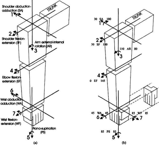
In the human arm there are three distinct joints that allow it to move. There is a wrist with three degrees of freedom (DOF), an elbow with one DOF and a shoulder with three degrees of freedom. Using guidelines from previous research done by Kapandji on human joints, I was able to recreate the biological joints into joints made of metal and mechanical components. See Figure 1 below for joint information.
0
4!
FIGURE 1. HUMAN JOINT RANGE OF MOTION AND TERMINOLOGY. JOINT ANGLES ARE FROM KAPANDJI 1982 (2)
In general, human arms diagrammatically show the wrist having three degrees of freedom. In the arm discussed here the pronation/supination movement has been translated into the forearm to allow for simpler mechanics while maintaining proper kinematics. Indeed, this appears more accurate when looking at the actual structure of the
human wrist and forearm complex. When a human wrist pronates, the forearm twists with it along its length. While the Anthro Arm does not twist the whole forearm, it does twist the axis of the wrist through the joint in the forearm.
Quickly going from a concept to fabrication required heavy design work using SolidWorks@2. As the design evolved from simple shapes to a more advanced
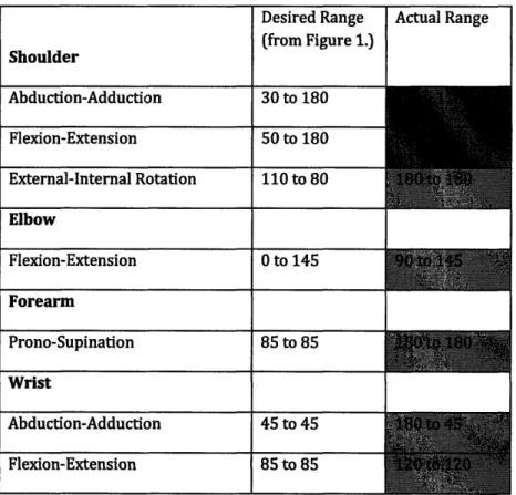
anthropomorphic arm, complexity increased and challenges quickly sprang up. Clearance issues became the continuous problem as ever incremental change in geometry changed how the pieces interacted with each other. Table 1 below shows the range of motion in the actual system as compared to a human arm.
TABLE 1. RANGE OF MOTION FOR EACH JOINT, DESIRED AND ACTUAL. Desired Range Actual Range
(from Figure 1.)
Shoulder Abduction-Adduction 30 to 180 Flexion-Extension 50 to 180 External-Internal Rotation 110 to 80 1U|1L... .I
bl
WI
I
I
Flexion-Extension 0 to 145 ForearmI
Prono-Supination 85 to 85Wrist
I
I
I
Abduction-Adduction 45 to 45 Flexion-Extension 85 to 85To accurately design the arm with the correct kinematics and human like motions,
computer aided solid modeling was extensively used. Creating design iterations on the computer allowed for easy changes before any physical parts were cut. Using Solidworks@ and a very detailed model allowed me to position joints and check for clearance along their full range of motion. Every part including fasteners was included in the model to make
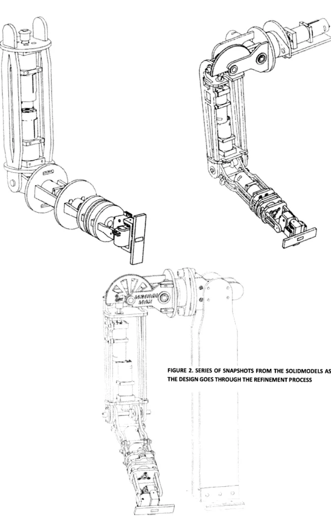
sure that it was accurate for testing. A specific model allowed for quicker fabrication times than if I were to have just modeled the main components. All the guesswork due to fit between parts was eliminated with a combination of detailed models and CNC machining. Even before some of the stock parts were ordered such as gears and motors, these parts were modeled with their specifications found on the manufacturer's data sheet and put into the final assembly on the computer. The next series of pictures below in Figure 2 show just a few snapshots of the solid model as it went through the design process. At each snapshot, it is easy to see the major changes that were made but countless smaller changes go unseen until the arm is actually fabricated.
j"E
7I
...~ •]i • ••••. : • 7 •••
--;;··-s.~- •'
FIGURE 2. SERIES OF SNAPSHOTS FROM THE SOLIDMODELS AS THE DESIGN GOES THROUGH THE REFINEMENT PROCESS
1i. 4 II
i'
14 V. VOut of the seven axes in the arm, three axes have an additional gear for transmitting power: two through miter gears and one through spur gears. I tried to keep this number to a minimum by directly attaching output shafts to joints where possible. On the joints that this did not end up happening, it was because doing so would prevent the motors from falling within the space constraints of the arm. Keeping motors internal to the frame of the arm was more important than adding one additional gear mesh for each of the three axes that needed this transfer of power. Each additional gear mesh that I would have had to design into the system would have resulted in significantly more precision needed when machining parts and a reduction in space efficiency. The planetary drives used instead offer compactness with a high efficiency gear reduction. The specific gearboxes chosen allow for interchangeability with other drive components. For a given size, different length ring gears can add or subtract gearbox stages, and the ability to swap different size motors in and out give flexibility to the system.
MODULARITY'
Designing this arm such that the platform was an open bed for future
research was critical to the project. In keeping with this idea, many of the main parts have a modular design component built in to the architecture of the piece. The motors are a standardized Mabuchi motor that can be swapped easily with the adjoining Banebots gearbox. If a motor were ever to burn out, new motors of the same type can be swapped
out but even if new specifications require a new type of motor, the gearboxes are flexible enough to accept a couple different sizes of motor. Each of the gearheads consists of replaceable bearing blocks and ring gears. If another gearing stage needed to be added, swapping a ring gear and adding another sun carrier is no problem. If the whole
motor/gearhead system needed to be removed, the mounting places in the robot are such that 6 out of 7 of the motors do not need any other parts to be removed before removing the motor. There is also additional space around the motor mounts in 4 out of 5 of the main joints to allow for future upgrading of larger or smaller motors. In the wrist, the
servos are a standard RC size making way for any future swap in servos simply a matter of unscrewing a few screws and swapping out the servo units.
The openness of the frame will provide a strong backbone for additional parts whether they are circuit boards, sensors, or mechanical components. In designing the forearm, specific areas were located for placement of control circuitry that will enable the adjoining hand. At the interface of the hand, a swappable piece is in place to give
maximum freedom for the end effector connection.
DESIGN FOR FABRICATION
The primary structure of the robot was designed to be able to be cut on a waterjet machine and then welded with very little extra machining. Absolutely every detail was included in the software solid model before beginning any machining. Once a precise software model was made, individual pieces are quickly and easily made because there is no guesswork and very little fitting to do. This allowed me to be very accurate and make few extra parts.
When designing for the waterjet, sometimes it is easier to make complex shapes or an assembly of simple shapes that can all be waterjetted where no extra machining is involved even if it requires more design time. Using the extra machine time to cut the longer paths or additional shapes if it allows less secondary machining is a model that I followed in designing the parts for the arm. The majority of the secondary machining that was needed came from non-through holes that were absolutely necessary and tapping for screws.
Keeping materials standardized sped up fabrication time as well. The majority of the parts were 2D shapes made out of standard .25" thick aluminum. Each of the pieces formed a piece in a 3d jigsaw puzzle. To facilitate construction, all of the pieces that needed to be welded had built-in indexing tools by design. The interlocking pieces had tabs so that the welders were able to use the pieces themselves as their own jig. Instead of needing to clamp plates together, all of the plates rested in slots keeping the stabilizing bars in line. Using this method, bearing holes remained concentric and shafts were able to turn freely.
An additional benefit is that it speeds welding prep time as the welder did not have to clamp and jig every piece.
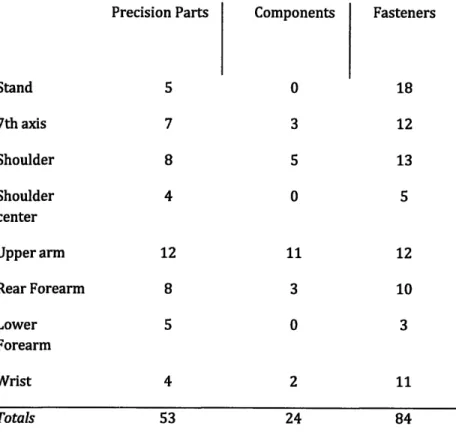
Utilizing the waterjet is beneficial in many ways but to get an accurate part, the machine must be calibrated. This is especially important when there are press fit bearings/bushings that need to go in waterjetted holes. In order to get this type of accuracy, a series of test cuts on the exact material were made on the machine using different offsets. Once I found the correct offset for a given material type and thickness, I could run the rest of the parts with the assurance that the parts will be accurate. In Table 2. Component Map a component map shows the composition of the arm as a sum of precision parts, off the shelf components, and fasteners.
TABLE 2. COMPONENT MAP
Precision Parts Stand 7th axis Shoulder Shoulder center Upper arm Rear Forearm Lower Forearm Wrist Components 0 3 5 0 11 3 0 2 Fasteners 18 12 13 5 12 10 3 11 Totals ACTUATION SCHEME
The choice for actuating robotic mechanisms are vast, including: shape memory alloy, pneumatic muscles, DC motors w/gearheads, direct drive motors, steppers,
and more. The pertaining functional requirements for the arm that narrowed the choices were mainly low cost, high familiarity and good power density. Shape memory alloy wires have a high power density but their performance is nonlinear. They require massive amounts of power and have limited precision. Pneumatic muscles also have a high power density but are fairly expensive and require a constant air supply. This air supply prohibits mobility that is eventually desired for this arm. Eventually, the choice was made to use geared DC motors. This decision was based on the availability of a low cost modular gearhead/motor that could provide the types of torques that were necessary for the arm.
There was another major design decision about whether to use tendon drives or shaft drives for each of the joints. In order to build a truly biomimetic arm, one would be required to use tendon drives that can accurately simulate muscle contraction. While a lot of research has been done in this area, most arms that have tried to use tendon drives use SMA, pneumatic muscles or DC motors driving pulleys and are simply not capable of the dexterity that a human arm is capable of demonstrating. Biology is an excellent craftsman being able to create all the muscles and connective tissues such that they work in perfect synchrony but recreating this in physical models is quite complex. A human arm has the benefit of multiple layers of natural shrouding from the micro level at the muscle fibers to the macro level of the outer skin. No mechanical equivalent is nearly as capable as human muscular system. So instead of spending a lot of time innovating actuators, it was more important for this project to work as we intended. In keeping with a simplistic and low cost model, DC motors transferring motion through shafts proved to be the best choice. Table 3 below shows the composition of each joint and what type of actuator is used and the correlating feedback mechanism.
TABLE 3. MOTOR AND ENCODER SELECTION FOR EACH JOINT
Actuator Feedback Mechanism
Shoulder
Abduction- Banebots 42mm 48:1 planetary gearbox, US digital MAE3 Miniature absolute
Adduction Mabuchi RS-550 motor magnetic encoder
Mabuchi RS-540 motor magnetic shaft encoder
External-Internal Banebots 36mm 125:1 planetary gearbox, US digital MA3 Miniature absolute
Rotation Mabuchi RS-540 motor magnetic shaft encoder
Elbow
Flexion-Extension Banebots 36mm 125:1 planetary gearbox, US digital MAE3 Miniature absolute
Mabuchi RS-540 motor magnetic encoder
Forearm
Prono-Supination Banebots 36mm 36:1 planetary gearbox, US digital MA3 Miniature absolute
Mabuchi RS-540 motor magnetic shaft encoder
Wrist
Abduction- Hitec HSR-5995TG Titanium geared R/C Potentiometer(built-in)
Adduction servo
Flexion-Extension Hitec HSR-5995TG Titanium geared R/C Potentiometer(built-in) servo
JOINT DESIGN
Figure 3. Simplified model of the Human Armbelow shows the basic kinematic model for a human arm. The Anthro Arm design needed to match this model as close as possible.
FIGURE 3. SIMPLIFIED MODEL OF THE HUMAN ARM (5)
SHOULDER
The most complicated joint of the robot is the 3 axis, spherical shoulder. In a human shoulder, the three axes of rotation are virtually spherical, meaning the center of rotation all go through the same point. To approximate the movements of a human shoulder, an asymmetrical spherical style shoulder joint was developed. Abduction and adduction are driven through a motor mounted to the inside of the arm, offset from the center of rotation. To transfer the torque from the motor to the arm, a gear train consisting of an off the shelf spur gear mounted to the motor meshes with a heavily modified spur gear mounted on a two-axis joint. Orthogonal to the previous axis is another axis that provides flexion and extension motion. The flexion and extension motions are powered through a miter gear mated to the two axes joint. The adjoining miter gear is attached to the shaft of a motor located in the upper arm. The two axis joint and large modified spur gear are the key components to giving the shoulder the proper range of motion. Adding redundancy to the system is a 7t axis that is the main connection between the base (artificial body) and the arm. I plwuJ a~~~ D I • lo jit o' Wristjoint -Ir
In order to get the proper range of motion, the two joint system in the shoulder had to be able to have axes that become concentric at their extents. To facilitate this, the
driving motor in the upper arm was offset towards the outside of the arm while keeping the center of rotation down the center of the arm. This gave enough room for the shaft of the motor to clear the shaft of the perpendicular axis as the two axes became coincident. It was just enough room to fit in a brass bushing but not a bearing such as those that are used elsewhere in the robot.
Using two half shafts in the center two axis joint became necessary so that the inner miter gear could, fit in. While it is easy to model a piece like this on the computer, it was important to think about assembly while designing. The two half shafts could be welded into place but the heat from the welding torch will most likely warp the parts. It will also be difficult to get these two pieces concentric without any reference. The solution was to weld in a full shaft, trying not to apply so much heat that the box deforms. After the parts were welded, the center was cut out to allow for the miter gear that goes in the center thus ensuring that that the shafts are concentric.
To transfer the rotational torque of the flexion and extension motions, a keyed steel flange was machined that mounts to the two axes joint. Instead of relying on the key through the aluminum, the steel flange will give the arm joint the needed linkage accuracy and reliability.
In reviewing the design for assembly, a big problem arose with the two main
shoulder plates that hang the arm away from the body. In the original design, these were to be welded in on both sides. If this were to happen, the shoulder joint would need to be placed captively between these plates before welding. This would also prevent the bearing from being replaced if this was ever needed in the future and would hamper arm
adjustment. A solution to this problem came in the form of a new front plate that had ribs and was bolted in. The rear plate was still welded in but with the removable plate in the front, the pieces of the shoulder could be removed and replaced if necessary.
In the 7th axis, a motor is sandwiched between two plates that are welded to a face
plate and bolted to the motor frame. This face plate holds a large pillow block bearing that takes a steel flange attached to the arm. The bearing in the pillow block will support the tremendous load caused by an outstretched arm on the motor. The shaft of the motor
extends past the face plate and well into the steel flange that is attached to the arm.
Because the shaft of the motor and the pillow block fit into the same piece, this steel flange must have a concentric inner and outer surface.
For feedback, a semi hollow encoder is placed on the abduction-adduction joint and the flexion extension joint on the shaft mounted towards the outside stabilizer plate. This location provided the best place for retaining joint motion and ease of access. On the body mounted 7th axis, a small plate was made to mount on the face of the motor to hold the encoder offset the motor shaft. The motor shaft and encoder shaft use a pair of lightweight plastic spur gears to transfer motion between each other.
ELBOW
Perhaps the simplest joint, the elbow has only 1 degree of freedom. Once again, the motor chosen was the 36 mm Banebots 125:1 planetary type. The motor was placed in the upper arm instead of the upper forearm to bring in the heavy masses as close to the base as possible. This reduces the torques needed on the links above it in the kinematic chain. To transfer power to the elbow shaft, the motor is linked via a set of straight cut miter gears. The miter gears are the same as in the shoulder and provide a 1:1 gear ratio. Transferring the torques through the shaft required keying the shaft and upper forearm stabilizer bars. To ensure reliable operation, a small steel flange was attached to the upper forearm such that the torque can be properly transmitted from the motor through the miter gears and into the lower arm. Locating the axle became a challenge in the tight space. A collar is mounted on the outside of the upper arm link towards the inside of the arm (towards where the body would be) and another thin collar next to the steel flange. A collar could not be positioned on the outside because it would conflict with the encoder placement.
In order to provide pronation/supination, the rotating function of the wrist was moved into the forearm. As previously mentioned, this was done to allow for simpler, more efficient mechanics while still providing the complete range of motion. The motor chosen for this application was based on the same 36mm platform as the other motors, but has a 36:1 gearbox for increased speed.
The lower arm is divided into two major sub-assemblies: lower forearm and the upper forearm. Connecting these two joints is the shaft of the motor. The long .375dia steel shafts that come standard on the gearboxes allow the design to do away with a lot of unnecessary hardware such as shaft couplers and bearings. Instead, the lower forearm rides directly on the gearbox shaft. To counteract moment forces on the gearbox, one additional bearing is located at the far end of the upper forearm. This bearing is also the point that stops the face plates of the two forearm assemblies from rubbing on each other.
Providing feedback for the mechanism, a shaft encoder is placed in
communication with the output shaft of the motor through a set of spur gears. The encoder is attached via the same plate that is on the face of the motor. It would have been ideal to not place a gear mesh between the encoder and the motor shaft but there is virtually no loading at the encoder so this should not be a problem. Placing the spur gears between the support plates forced the motor attachment points to move from the face of the front bearing block to the outside stabilizer bars. In designing for assembly, it was important to envision putting the machine together but also making sure that all parts could be easily removed and replaced.
WRIST
The wrist: is centered on two Hitec servos (HSR-5995TG). Each of these servos is in a custom aluminum bracket that is designed such that the two axes are perpendicular and the total package is the smallest possible. The symmetrical brackets have cutouts that permit each piece to interlock with each other prior to welding. This keeps the pieces aligned and straight. For power take off, each of the servos has an aluminum servo horn on
one side and m3 tapped bushing on the other. While only the horn is powered, both sides were utilized to prevent cantilevering of the connecting link. A pressed bushing in the
adjoining aluminum held a shoulder screw that went into the m3 tapped hole in the bottom of the servo. This provided a strong connection yet still provided low friction for rotation. On the far end of the wrist, a blank aluminum plate is provided for the later addition of a hand. It was designed to be modular so this piece is easily taken on and off.
Actuating the wrist required two very power dense motors. Incredible advances in the RC industry have brought small servos to the point where they are very well adept at handling big loads in a small package. The servos chosen for this scenario have the highest torque rating in the industry contained in the standard RC servo size. In order to do this, these small systems have digital controllers, titanium gears, and high powered motors. These were chosen because the wrist needed to be able to provide the most amount of torque (416 oz-in) in the smallest package possible to maintain human wrist-like size.
Even though the servos can hold an incredible amount of torque for their size, they became the limiting factor when computing max payload.
CONTROLS
By virtue of muscle tendons and a complex neurological network, it is possible for
our brains to easily compute path planning and error correction. In the Anthro Arm, it will take feedback mechanisms and advanced controllers in order to make the arm function.
Feedback for joint position of the arm is dependent on 5 absolute magnetic encoders and two potentiometers. The reason for the awkward combination of encoders and
potentiometers is because the two pots are built into the Hitec servos in the wrist. Instead of adding another layer of control on top of the servos, it was decided for simplicities sake to utilize the existing feedback mechanism built into the small hobby servo package. Using absolute encoders instead of incremental encoders was a conscious decision because of an absolute encoder system's ability to always know their position. It is inherently safer to rely less on the controller than on the physics of the hardware. With the eventual
intention of using this arm around people, it is important to integrate as much safety into
the system as possible. If incremental encoders were used and the arm's controller was to skip counts it would quickly lose track of its exact position. As the system continues
operating, the accuracy will wander until the machine is homed again. This is clearly not a good scenario but luckily it can totally be alleviated by using absolute encoders.
Enabling the arm to use absolute style encoders is the recent miniaturization and cost reduction of these types of feedback mechanisms. Previously, absolute encoders were prohibitively expensive costing hundreds of dollars per piece. US digital has developed a low cost version in an ultra small package. I chose to use two shaft type and 3 semi-hollow versions of the same style encoder. One of the features of the integration of the encoders into the arm is that with this modular architecture, I was able to place the encoders after all loaded gearing and put them directly onto the rotating joints. Locating the encoders on the joints and after all gear meshes reduces controller complexity. Often, the encoders are placed directly on the motors and before gear trains. This suboptimal design reduces the high accuracy encoders into low accuracy feedback mechanisms when the lash from the geardrives gets magnified by the length of the arm. Software can try to counteract this with
careful arm modeling but it is not a trivial task. Two of the joints do have the encoders after a set of gear mesh but this was not able to be avoided. In addition, these gear meshes are unloaded and have very low backlash due to precise gearing. If the lash does end up being a problem, due to the modular design, it would be trivial to swap the traditional spur gear with a zero-backlash style gear.
FURTHER WORK
The arm is at the point where it needs control electronics and motor drivers for it to be fully operational. The absolute encoders are all installed along with the motors. The system is ready to be plugged in and used. Once the control electronics are developed, the system will need to be tuned with the right gains to achieve stable motion. Mechanically, the only area left to be developed is where the hand interfaces with the end of the wrist. Because the latest generation of hand is still in the development phase, the arm interface
could not be fully defined. An open mounting plate with plenty of space was designed instead to provide a flexible base for the future hand/wrist connection point.
The idea has been laid out to use the arm as a mechanical teaching tool to catalog trajectory and position profiles. At the beginning of the project, it was determined that backdrivability of the system was a must have in order that the arm could be used as a data
capture device when driven externally. This mode of operation would give researchers the capabilities to run the data simplification algorithms mentioned previously. By externally guiding the arm and recording joint locations while performing basic tasks, eventually enough data will be captured to perform a reduction analysis producing a set of motion primitives. The set of motion primitives will form the basis for the study of using a
complicated Multi-degree of freedom arm in an application with limited data outputs such as a brain-machine interface.
FINAL CONSIDERATIONS
Using computer aided modeling coupled with CNC tools like the waterjet significantly sped up the design and fabrication processes for this arm. Without tools such as these, it would have taken many more design iterations and multiple prototypes before a working arm could have been completed.
For the next generation of Anthro Arm, a new type of shoulder mechanism would need to be created. While the three axes of the shoulder are indeed spherical, the home position of the joint that provides internal-external rotation is not correct. In order to update the system, the 7th axis joint should be moved after the two axes shoulder joint in the kinematic where as it is before it in the current version. A byproduct of this redesign would be a new shoulder structure that could provide more range of motion than what is allowed in the current generation. This would make the arm even more biomimetic than it is in its current configuration.
REFERENCES
1. Design and Application of a 3 DOF Bionic Robot Arm. Klug, Sebastian, et al. Illmenau, Germany : s.n., 2005.
2. A Seven-degrees-of-freedom Robot-arm Driven by Pneumatic Artificial Muscles for
Humanoid Robots. Tondu, B., et al. s.l. : International Journal of Robotics Research, 2005.
3. Optimum Kinematic Design for a Seven Degree of Freedom Manipulator. Hollerbach, John
M.
4. Kinematic design of a humanoid robotic shoulder complex. lenarcic, jadran, Stanisic,
Michael M. and Parenti-Castelli, Vincenzo. San Francisco, CA : International Conference
on Robotics & Automation, 2000.
5. Cora: An Anthropomorphic Robot Assistant. Iossifidis, loannis, et al. Germany : s.n. 6. Design, actuation and control of an anthropomorphic robot arm. Tuijthof, Gabrielle J.M.
and Herder, Just L. s.l.: Mechanism and Machine Theory.
7. Design and Control Architecture of an Anthropomorphic Robot. Berns, K., et al.
APPENDIX A: RENDERED DRAWINGS
:9 .tr~
APPENDIX
C:
ENCODER DATA SHEET
MA3inatueAbslt..geicSat-noe
i.
Description:The MA3 is a miniature rotary absolute shaft encoder that reports the shaft position over 360' with no stops or gaps. The MA3 is available with an analog or a pulse width modulated (PWM) digital output
Analog output (MA3-A) provides an analog voltage that is proportional to the.
absolute shaft position. Analog output is only available in 10-bit resolution.
PWM output provides a pulse vndth duty cycle that is proportional to the absolute shaft position. PWM output is available in 10-bit (MA3-P) and 12-bit (MA3-P12)
resolutions. The accuracy is the same for both resolutions, even though the 12-bit version offers higher resolution.
Three shaft torque versions are available. The standard torque version has a sleeve
bushing lubricated with a viscous motion control gel to provide torque and feel thatv
is ideal for front panel human interface applications.
The NT-option (no torque added) has a sleeve bushing and a low viscosity lubricant
(that does not intentionally add torque) for low RPM applications where a small. amount of torque is acceptable.
The 88-option (ball bearing option) has a ball bearing rather than a sleeve bushing for high speed, free spinning. and zero torque applications. The B8-option is:
recommended when a pulley, gear, orfriction wheel drives the shaft This eliminates: the wear that would otheriwise result from the side load even at slow speeds. The
shaft diameter for 88-option is 1/8" rather than 1/4".
Connecting to the MA3 is simple. The 3-pin high retention snap-in 1.25mm pitch polarized connector provides for +5V, output, and ground. Note thatthe MA3 has a 3-: pin connector and issmallerthan it's predecessor, the MA2 which hasa 4-pin connector.
Features:
.Patent pending
;Low cost
SMiniature size (0.408 diameter)
Non-contacting magnetic single chip sensing technology
>-40 to "125'C. operating temperature range
- 10-bit Analog output -2.6 kHz sampling rate (MA3-A)
> 10-bit PWM output - 1024 positions per revolution, 1 kHz (MA3-P)
; 12-bit PWM output -4096 positions per revolution, 250 Hz (MA3-P12)
- RoHS compliant
SUS Digital warrants its products against defects in materials and
workmanship fo• two years. See complete warranty for details.
Applications:
>Front panel control
-Camera pan-tilt position sensor Rotary valve position sensor
>Rotary air duct valve position sensor ;Studio lighting position feedback
> Office equipment
MA2 I MA3 Comparison: Magnetic Field Crosstalk to
US Digital continually seeks to improve our products by making them smaller, faster, Neighboring Encoders:
more accurate, and lower cost. We found a way to make the MA2 even smaller by The MA3 absolute encoder contains a small internal magnet,
changing the connector from4-pins to 3-pins. This new productbecame the MA3 and mounted on the end of the shaft that generates a weak magnetic
onty has adiameter of 0.48". This next generation MA3productis highly recommended field extending outside the housing of each encoder. If two MA3:
for all new designs and applications units are to be installed closer than 1 inch apart (measured between the center of both shafts), a magnetic shield, such as a small steel
Feature MA2 MA3 plate should be installed in between to prevent one encoder from Size 0.62" dia. 048" die. causing small changes in reported position through magnetic field
Weight 0.56 oz. 0.46 oz. cross-talk.
Connector 4-pin 3-pin
Price No Difference in Price
Mechanical Specifications: Electrical Specifications:
Specification Sleeve Bushing Ball Bearing ;-Specifications apply over entire operating temp. range.
(Default, 8-option, M6-option) (B8-optlonj - Typical values are specified at Vcc=+5SV and 25"C.
Moment of Inertia 4.ix-lx0 oz-in-s 4.1x0I oz-in-s= Parameter Min. Typ. Max. Units Accuracy <c0.5' @ 25'C <±0.5 @ 25'C Power Supply 4.5 5.0 5.5 Volts
Over Temp. '<0.9' q-40 to 125'C c<±.9' g -40 to 1252C Supply Current 16 20 mA
Shaft Speed 100 RPM max. continuous 15,000 RPM max. continuous Power-up Time - 50 ni
Acceleration 10,000 rad/sec' 250,000 radlsec2
Vibration 20 g. 5 to 2KHz 20 g. 5 to 2KHz Materials:
Shaft Torque 0.5 ±0.2 in. oz. 0.05 in. or max. Parameter Dimension
0.3 in. oz max. (NT-option) Shaft Stainless
Shaft Loading 2 lbs. max. dynamic* 1 lb. max. Bushing Brass
20 lbs. max. static
Beanng Life - (4UP)' = tife in millions of revs. Environmental Specifications:
where P = radial load in pounds Parameter Dimension Weight 0.46 oz. 0.37 oz. Operating Temperature -40 to +1256C Shaft Runout 0.0015 T.I.R. max. 0.0015 ST.I.R. max. Storage Temperature -55 to +125'C
When a pulley, gear, or friction wheel drives the shaft, the Ball Bearing option is recommended ESD 2kV minimum
instead of the Sleeve Bushing. Humidity Non-condensing 5 to 85%
U S m
ULocal:
info@usdigital.com @ www.usdigital.comrn360.260.2468 a Sales: 800.736.0194
Support: 360.397.9999 a Fax: 360.260.2469 page
£E
Abolt Manei Kit Encode
Description:
The MAE3 is an absolute magnetic kit encoder that provides shaft position information over 360' of rotation with no stops or gaps. This magnetic encoder is designed to easily mount to and dismount from an existing shaft to provide digital feedback information.
Analog output (MAE3-A) provides an analog voltage that is proportional to the absolute shaft position. Analog output is only available in 10-bit resolution. PWM output provides a pulse width duty cycle that is proportional to the absolute shaft position. PWM output is available in 10-bit (MAE3-P) and 12-bit (MAE3-P12) resolutions. The accuracy is the same for both resolutions, even though the 12-bit
version offers higher resolution.
The MAE3 consists of three components: base, push-on magnetic hub, and encoder body. The base will acconmmodate a 0.750" mounting bolt circle. No tools are needed
for the push-on, collet gripping hub. The hub mounts to a standard shaft in seconds
and provides a simple and reliable means of securing the magnet to the shaft. Two 4-40 pan head screws secure the base and encoder body to any flat surface. If desired, the encoder can be powered up and rotated by hand to any desired; absolute position before the screws are tightened.
Connecting to the MAE3 is simple. The 3-pin, high retention, snap-in 1.25mm pitch polarized connector provides for +5V, output, and ground.
Mechanical Specifications:
Parameter Dimnelsioh Units
Moment of Inertia 8.49 x 'iO- oz-in-s:
Mounting Screw Size (pan head) 4-40 x 1/4"
Required Shaft Length
Size 220 Shaft Length-option 0.220 (+0.04 / -0.2) in. Size 500 Shaft Length-option 0.500 (+0.04 / -0.02) in.
Absolute Maximum Ratings:
Parameter Max. Units Vibration (5 to 2kHz) 2z 9
Shaft Axial Play .0.025 in.
Shaft Eccentricity Plus Radial Play 0.004 in. Acceleration 250,000 rad/sec
> Note that radial play translates directly to postion inaccuracy.
Electrical Specifications:
> Specifications apply over entire operating temperature range.
>Typical values are specified at Vcc=+5V and 25"C.
Parameter Min. I yp. Max. Units
Power Supply 4.5 5.0 5.5 Volts
Supply Current - 16 20 nA
Power-up Time - - 50 nS Mechanical Drawing:
Size 500 Shaft Size 220 Shaft
Length-option Length-option
A &"*I ti
Features:
-Patent pending
>Low cost
Quick, simple assembly and disassembly
>-40 to +1250C operating temperature >Accepts ±.010" axial shaft play
> Mounts to 0.750" bolt circle
> Fits shaft diameters from .125" to .250"' or 2mm to 6mm , 10-bit Analog output -2.6 kHz sampling rate (MAE3-A)
-10-bit PAM output - 1024 positions per revolution, 1 kHz (MAE3-P)
> 124AitPM output- 4096 positions per revolution, 250 Hz(MAE3-P12)
> RoHS compliant
;US Digital warrants its products against defects in materials and workmanship for two years. See complete warranty for details.
Applications:
-Motor Position sensor
>Camera pan-tilt position sensor
" Rotary valve position sensor
SAir duct damper position sensor
, Studio lighting position sensor
: Office equipment
Torque Specifications:
Parameter T
Base t Mounting S~urface
orque 4-b in.-I•s. Environmental Specifications: Parameter Dimension Operating Temperature -40 to +125CC Storage Temperature -55 to +125TC ESD 2kVminimum Humidity Non-condensing 5 to 85% U S m= info@usdigital.com a www.usdigital.com Local: 360.280..2468 a Sales: 800.736.0194
Support: 360.397.9999 a Fax: 360.260.2489 page
D
I
I T
A
L
1400 NE 136th Ave.Vancouver,
Wasington 98684 USA. . .. , .- -- , - ., . . ..
,
o
.53t
APPENDIX D: SERVO SPECIFICATION SHEET
PREPARED BY JUN IeEE,LEE
GENERAL
SPECIFICATION OF
UPDATEJAN 01.,2004HSR-5995TG CORELESS DIGITAL SERVO
ITECHNEAL VALUE
CONTROL SYSTEM
OPERAT ING VOLTAGE RANGE
OPERATING TEMPERATURE RANGE
TEST VOL'AGE
OPERAT ING SPEED
STALL TORQUE STANDING TORQUE
IDLE CURRENT
RUNN ING CURREN T STALL CURRENT
DEAD BAND I IDTH OPERAT ING TRAVEL DRECT IDN
MOTOR TYPE
POTENT 101 ETER TYPE AMPLIFER TYPE
DI ENSIONS
I EIGHT BALL BEARING
GEAR MATERIAL
HORN GEAR SPLINE
SPLINED HORNS
CONNECTOR I RE LENGTH
CONNECTOR I RE STRAND COUNTER CONNECTOR IRE GAUGE
*PULSE I IDTH CONTROL 1500usec NEUTRAL
4SV TO 6DV
- 200C TO + 601C(-68 F TO + 1400F)
AT 6.O AT 7AV
:015sec)A0S AT NO LOAD 0.12sec/600 AT NO LOAD
2.4Dkgca (333 29oz:m) 30 Dkg um (416 1 loz.i)
:31 2kga (433 27oz.i0n)S] HOLD OUT 39kg.cm (541 59oz.a)/15 HOLD OUT 3mA AT STOPPED 3SA AT STOPPED
:300m A0 LOAD RUNNING 380n AiMO LOAD RUNNING
4200m A 5200m A
:2usec 2usec
9009WONE SIDE PULSE TRAVELING 400usec CLOCK I ISEIPULSE TRAVELING 1500 TO 1900usec CORELESS M ETAL BRUSH
6 SL IDERIlNDIRECT DRIVE
DEIGITAL AMPLIFPER ITrH M OSFET DRIVE :40x20x37a m (15 7x0128l A5h)
$2g(2 18oz)
DUA Lil 1106 fT IAN UI ALLOY :24 SEGM ENT SA95,576
SEGULAR ETAL-IL L 300m (11blik) £OEA :22A I G TAPPED 2 FEATURE!
PROGRAlIl ABLE DIGff AL All PLFIER I ffTH11 OSPET DRIVE
DURABLE T TAN IU ALLOY METAL GEARSI IT 1 DUAL BALL BEARING ULTRA HARDNESS SHAFT I f1r 3 AXIAL METAL BUSH ING
ER & DUST T IGHT
TON SIDE AXIALIMOUNT HOLE
3APPLICAT UNS ROBOTS
APPENDIX
E::
BANEBOTS MOTOR SPECIFICATIONS
125:1 36mm RS-540 Gearmotor Specifications Physical Type :Planetary Reduction :125:1 Stages : 3Gear Material : All Metal
Weight (Gearbox only) : 7.2 oz (205g)
Weight (with motor) : 12.6 oz(358g)
Length (Gearbox only) :1.9 in (49mm)
Length (with motor) : 4 in (102mm)
Width (Square) :1.5 in (38mm)
Shaft Diameter : 0.375 in (10mm)
Shaft Length : 2.15 in (55mm)
Shaft Key : 0.125 in (3.2mm)
Shaft End Tap : #8-32
Mounting Holes (12) : #10-32 Calculated Performance* Motor : RS-540 (Pinion) Operating v : 4..5v - 12v Nominal v : 12v No Load RPM : 134 No Load A : 1A
Stall Current : 42A
Stall Torque : 4935 oz-in 34849 mN-m
Kt : 117.5 oz-in/A 830 mN-m/A
36:1 36mm RS-540 Gearmotor Specifications
Physical
Type :Planetary
Reduction : 36:1
Stages :3
Gear Material : All Metal
Weight (Gearbox only) : 7.2 oz (205g)
Weight (with motor) : 12.6 oz(358g)
Length (Gearbox only) :1.9 in (49mm)
Length (with motor) : 4 in (102mm)
Width (Sqaure) : 1.5 in (38mm)
Shaft Diameter : 0.375 in (10mm)
Shaft Length : 2.15 in (55mm)
Shaft Key : 0.125 in (3.2mm)
Shaft End Tap : #8-32
Mounting Holes (12) :#10-32 Calculated Performance* Motor : RS-540 (Pinion) Operating v : 4.5v -12v Nominal v :12v No Load RPM :467 No Load A :1A
Stall Current : 42A
Stall Torque : 1421 oz-in 10036 mN-m
Kt : 33.8 oz-in/A 239 mN-m/A
Kv : 39 rpm/v
Type : Planetary
Reduction :48:1
Stages : 3
Gear Material : All Metal
Weight (Gearbox only) : 11.8 oz(335g) Weight (with motor) : 19.5 oz(553g) Length (Gearbox only) : 2.1 in (52mm) Length (with motor) : 4.3 in (109mm) Width (Square) : 1.75 in (44mm)
Shaft Diameter : 0.5 in (13mm) Shaft Length : 2.15 in (55mm)
Shaft Key : 0.125 in (3.2mm)
Shaft End Tap : #:8-32
Mounting Holes (12) : #10-32 Calculated Performance* Motor : RS-550 (Pinion) Operating v : 6v -14.4v Nominal v : 12v No Load RPM :402 No Load A : 1.2A
Stall Current : 85A
Stall Torque : 3386 oz-in 23913 mN-m
Kt : 39.8 oz-in/A 281 mN-m/A
Kv : 34 rpm/v
*All performance numbers are calculated using motor data at Nominal Voltage. They do not factor in loss