XVII. APPLIED PLASMA RESEARCH
A. Active Plasma Systems
Academic and Research Staff
Prof. L. D. Smullin Prof. R. R. Parker Prof. R. J. Briggs Prof. K. I. Thomassen
Graduate Students
Y. Ayasli P. J. McCleer J. A. Rome
J. A. Mangano M. I. Mirkin J. M. Tarrh
RESEARCH OBJECTIVES
The research of the Active Plasma Systems Group is primarily concerned with the behavior of highly ionized plasmas and charged-particle beams, with particular empha-sis on the understanding of wave interactions in plasmas. Some of the major areas of investigation are listed below.
1. Plasma Source
A dense, highly ionized plasma source using a pair of hollow beam electron guns is being constructed. Plasma is produced in small chambers on each end of the device by beam-plasma interactions. The beams are collected on an annular plate and the hot plasma drifts into the differentially pumped central chamber. The goal is to achieve densities greater than 101 2/cm 3 and temperatures from 10-20 eV, with as low a neutral background pressure as possible.
R. R. Parker, K. I. Thomassen
2. Stochastic Heating
Using a microwave noise tube we are exploring the problem of stochastic ion heating at the lower hybrid frequency in a magnetic mirror. The frequency spec-trum of the source spans the range of hybrid frequencies in the mirror. The objec-tives are to determine the efficiency of this method of ion heating, and to compare the velocity distribution with those obtained by coherent signal sources.
K. I. Thomassen
3. Direct Conversion
The direct conversion of the kinetic energy of energetic ions streaming out of a thermonuclear reactor to electrical energy offers many advantages. Studies of the energy conversion between energetic ions with a fairly broad energy spectrum and a traveling electrostatic wave are under way.
R. J. Briggs, R. R. Parker
4. Stability of Sheared Electron Flow
Our investigations in this area are nearing completion. A fairly detailed under-standing of the instability modes in magnetically confined electron beams with veloc-ity shear has been obtained, and a very efficient numerical scheme for obtaining the eigenfrequencies in such systems has been developed which is applicable to a wide variety of plasma instability problems.
R. J. Briggs 5. Interaction of a Heavy Ion Beam with a Plasma
A potassium ion beam is injected into a hydrogen plasma to study the interactions of charged-particle beams with plasmas in the regime where the beam speed is comparable to the ion acoustic velocity. These interactions are of interest from the standpoint of ion heating by charged-particle beams.
R. J. Briggs 6. Plasma Heating at Hybrid Frequencies
During the past year, we have concluded a study of ion-cyclotron heating of a beam-generated plasma. Although ideally suited for mirror geometries, this heating scheme is not particularly attractive in toroidal geometry. Thus, we plan to inves-tigate other heating methods; in particular, heating at hybrid frequencies. The study will examine effects of density profile, wave number parallel to B and mode con-version mechanisms responsible for energy absorption.
R. R. Parker 7. Microwave Scattering from Beam-Plasma Interactions
The objective of this work is to develop microwave scattering techniques for the purpose of measuring wave number and frequency spectra of plasma instabilities and fluctuations. By applying these techniques to beam-plasma discharges, we hope to shed further light on the nature of the interactions. Although X-band has been used thus far, we plan to extend the work to the millimeter range. We also plan to explore the feasibility of far infrared scattering with eventual application to Alcator.
R. R. Parker
XVII. APPLIED PLASMA RESEARCH
B. Plasma Physics and Engineering Academic and Research Staff
Prof. R. A. Blanken Prof. E. P. Gyftopoulos Prof. L. M. Lidsky
Prof. T. H. Dupree Dr. E. Oktay
Graduate Students
G. W. Braun B. H. Hui A. Pant
D. L. Cook D. S. Komm C. A. Primmerman
J. C. Hsia T. A. Moulia J. E. Robinson
RESEARCH OBJECTIVES
1. Nonlinear and Turbulence Theory of Plasmas
Plasma processes that depend upon particle discreteness can be greatly enhanced by the tendency of turbulent plasma to develop small-scale phase space granulations, or clumps. Such granulations can, in some circumstances, behave as single large par-ticles, or macroparticles. We propose to derive and solve the equations for clump for-mation and evolution. We hope to apply this theory to a variety of physical problems. We shall continue our study of nonlinear dispersion relations for both high- and low-frequency instabilities; particularly, we intend to use the dispersion relation to predict the saturation levels and other turbulence properties measured in several recent experiments.
T. H. Dupree 2. Turbulence and Diffusion in a Highly Ionized Plasma Column
Although it is generally agreed that fluctuating electric fields are the cause of exper-imentally observed enhanced plasma transport, the expected quantitative relations between the magnitude and frequency of the fluctuations and the speed and direction of transport are not often satisfied. We have developed a new technique from the direct measurement of diffusion flux and are using it to investigate plasma flows in a radiofrequency-produced collisionless plasma column. We have discovered large-scale rotating vortices that appear to be the nonlinear limit of the Kelvin-Helmholtz shear instability. We shall try to understand their role in transport and compare the nonlinear saturated state with theoretical predictions.
T. A. Moulia, J. E. Robinson, E. Oktay, L. M. Lidsky 3. Investigation of Velocity Space Instabilities
Existing apparatus will be modified to produce a minimum B mirror device designed expressly for the detailed study of velocity space instabilities. We plan to observe the development and saturation of specific instabilities. Principal diagnostics will be ultrahigh-frequency probes (for measurement of temporal and spatial development) and
coherent scattering (for direct observation of s(w, k)).
R. A. Blanken
4. Far Infrared Plasma Diagnostics
We plan to construct several dual-purpose lasers that will operate on either HCN or HZO. Suitable optics will be developed and the lasers used for diagnostics in several plasma experiments. The 3371 HCN line is particularly suitable for use in our experi-mental investigations of velocity space instabilities.
J. C. Hsia, R. A. Blanken 5. High-Power Laser Development and Applications
The high-power TEA laser will be investigated in an effort to develop a light source suitable for plasma diagnostics in the coherent regime. Such a laser might, for example, be used in Alcator to measure the radial distribution of ohmic heating current. The transverse-flow cw laser will be further investigated in our continuing effort to develop a low-cost stabilized discharge laser in the 500-1000 W range. This is suitable for laboratory studies (electrode-heating thermionic diodes and plasma sources, for example) and various industrial uses.
C. A. Primmerman, L. M. Lidsky
XVII. APPLIED PLASMA RESEARCH
C. Plasma Effects in Solids
Academic and Research Staff Prof. A. Bers Dr. L. D. Pleasance Graduate Students J. H. Cafarrella C. M. Krowne RESEARCH OBJECTIVES
During the past year we have concluded1' 2 our work on noise emission from InSb. This year we are redirecting our activities in the area of plasma effects in solids. We have initiated new work in high-frequency (UHF and microwave) acoustic surface wave amplification and coupling. In this work we have pointed out the possibility of a resonant interaction between acoustic surface waves (in piezoelectrics) and free electrons (in semiconductors) in applied electric and magnetic fields. Our recent experiments give a preliminary confirmation of the theory. During the next year we plan to focus our efforts in this area. The experimental work will be carried out with the help and col-laboration of the Microsound Group at Lincoln Laboratory, M. I. T.
A. Bers References
1. E. V. George and G. Bekefi, Appl. Phys. Letters 15, 33 (1969). 2. A. Bers and R. N. Wallace, Phys. Rev. Letters 25, 665 (1970).
1. OBSERVATION OF INTERACTION BETWEEN ACOUSTIC
SURFACE WAVES AND ELECTRON SURFACE WAVESt
We report the experimental observation of resonant coupling and amplification of acoustic surface waves on a piezoelectric with electron surface waves on an adjacent semiconductor in a transverse magnetic field.
Room-temperature measurements were made at 30 MHz and 150 MHz on an LiNbO3 -GaAs structure, using magnetic fields of up to 144 kG.
It has been shown in a recent theoretical paperl that acoustic surface waves on a piezoelectric can interact resonantly with electron surface waves propagating on an
This work was supported by the National Science Foundation (Grant GK-18185), and in part by Lincoln Laboratory Purchase Order No. CC-554.
tThis work was supported in part by the U. S. Navy (Office of Naval Research) under Contract N00014-67-A-0204-0019. Part of this work was performed while one of the authors (C. K.) was a Guest Scientist at the Francis Bitter National Magnet Laboratory, which is supported by the Air Force Office of Scientific Research.
adjacent semiconductor in a transverse magnetic field. This wave -wave coupling differs markedly from the well-known nonresonant interaction of acoustic waves with drifting electrons.2 The former involves the excitation of a relatively well-defined electron sur-face wave, whereas in the latter the wave is entirely established by the acoustic system. The resonant interaction is of particular interest because it provides a means of studying the stable propagation of electron surface waves on semiconductors,3 and also for its applicability to investigation of the detailed electrical properties at the surface of a
semiconductor.
The dispersion relation for the coupled waves, including the effects of diffusion and with arbitrary values of b
E
jB (wherevi
is the electron mobility, B is the magnetic field), for a semiconductor with a depletion region of depth d, which is separated from the piezoelectric by a negligibly small air gap, is given byl' 42
Rcw
(l-Q)
(k-k )(k-k ) K (b-j) (la) (k-ka)(k-k e 2 va v o (l+jbQ)Rw
(I
-Q
+Q/R)
k -- + T (b-j) (lb) e vo v (1 +jbQ) K Av 1 - tanh kd (c) 2s I + (E /E ) tanh kd 1 + (E /Es) tanh kd R = (Id) (1+E /s )(1+tanh kd) 1/2jW/WD
Q= J / (le)(kvo
/w)
-
+ j
(W/+w/
D
where the coupled-wave fields are assumed to have angular frequency w and wave number k along the direction of propagation, ka is the wave number of the acoustic surface wave when the semiconductor conductivity -o = 0, k is the wave number of the electron surface wave when (Av/v) is zero, K is the effective electromechan-ical coupling constant, (Av/v)s is the fractional change in the acoustic phase velocity
5 2"-1
when
a-
changes from infinity to zero, c = (- /E )(l+b ) is the dielectric relax-ation frequency in the magnetic field, D = (c/k)2 (1+b2)e/KT[ is the electron diffusion frequency in the magnetic field, E and E are the dielectric constants for thep s
(XVII. APPLIED PLASMA RESEARCH)
piezoelectric and semiconductor, respectively, v0 is the electron drift velocity, and va
is the velocity of the acoustic surface wave on the piezoelectric in the absence of the semiconductor. The factor R represents a reduction in the effective electron con-ductivity for the interaction arising from the geometry and the differences in dielec-tric constants. The effective electromechanical coupling constant K is similarly affected and thus becomes frequency-dependent. The factor Q arises from the effects of electron diffusion, because of their finite temperature T.
The sample geometry, and the positive-polarity directions for the magnetic 'field and the electron drift velocity are shown schematically in Fig. XVII-1. It can be shown that for b >0, a weakly damped (Im ke << Re k e) electron wave has a negative small-signal energy and hence can amplify the acoustic wave. For b < 0, the inter-action between the acoustic and electron surface waves is that of a coupler, since both waves are positive-energy modes. In our particular experiments, in which acoustic waves are excited and detected, the coupling is manifested as a transfer of energy from the acoustic to the electron wave system.
DRIFT-FIELD PULSE
SIGN
INPU IVER
/
Fig. XVII-1. Schematic of the sample configuration showing the positive -polarity directions for the magnetic field B and the drift velocity vo.
The acoustic surface waves, propagating along the Z direction on a Y-cut polished surface of single-crystal LiNbO3, were generated and detected by a pair of inter-digital transducers, of 30-MHz fundamental frequency, spaced 1. 3 cm apart. The GaAs crystal, 8 mm X 3 mm X 0. 3 mm, had its front surface optically polished
by using a chemical-mechanical polishing procedure. The two ohmic contacts for the drift field were placed along the 3-mm edge on the rear surface of the crystal.7
The interaction length, that is, the region over which the GaAs and LiNbO3 were in close proximity (<1000 A), was 5 mm long.
Room-temperature measurements were made at 30 MHz and 150 MHz, with mag-netic fields up to 144 kG. A low duty-cycle drift field pulse (10 is at 25 pps) was used to avoid sample -heating problems. The acoustic gain that is due to the interaction was determined by measuring the changes with drift field or magnetic field of the sample's insertion loss in an RF circuit. The reference level for zero amplification was taken to be the insertion loss when v = v .
o a 40 - 30 MHz E 30-20 1-< 10 - B<0 / / - 0 1 I 0 40 80 120 0 40 80 B (kG) B (kG)
(a)
(b)
Fig. XVII-2. Acoustic surface-wave attenuation as a function of magnetic field, with no applied drift field, at (a) 30 MHz and (b) 150 MHz. The theoretical curves (dotted lines) are calculated from Eq. 1,
2 -1 -1
using an electron mobility t = 5000 cm V s , a free carrier 13 -3
density n0 = 1.3 X 10 cm , and a depletion-region depth
-4 d = 2.1 X 104 cm.
Figure XVII-2 shows the observed acoustic surface-wave attenuation as a function of magnetic field for both 30 MHz and 150 MHz. In the absence of a drift field, and with diffusion neglected (Q = 0), the maximum interaction occurs when W Z -RW b. As we shall show, this condition is nearly satisfied at 150 MHz for the highest negative -polarity mag-netic field. For positive-polarity magnetic fields, w >> -Rw b for both 30 MHz and
150 MHz; hence, the observed attenuations are very small.
The theoretical curves here, and in Figs. XVII-3 and XVII-4, were calculated from 2 -1 -1
Eq. 1, under the assumptions of an electron drift mobility L = 5000 cm V s , a free
(XVII. APPLIED PLASMA RESEARCH)
13 -3 -4
carrier density n = 1. 3 X 10 cm , and a depletion-region depth d = 2. 1 X 10 cm in the GaAs. These three parameters were chosen to fit the experimental data in Fig. XVII-2 and to be within the range of expected values as determined from indepen-dent measurements of the electrical properties for this and other samples from the
same boule. For simplicity, the air gap was neglected in the theoretical calcula-tions, since its effect was minor compared with that of the depletion region.
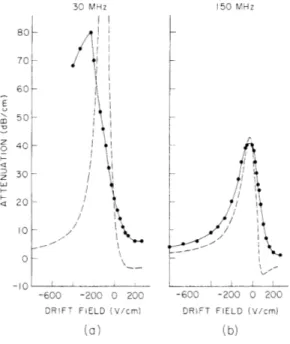
In the presence of a drift field, and with -b >> 1, the maximum coupling between acoustic- and electron-wave systems occurs when ka = ke ; that is, (Vo/V ) 1 + Rw b/w, with diffusion neglected. Figure XVII-3 shows the acoustic surface-wave
30 MHz 150 MHz
30 MHz 50 MHz
Fig. XVII-3.
Acoustic surface -wave attenuation as a func -tion of electric drift field, with B = -140 kG (coupler) at (a) 30 MHz and (b) 150 MHz. The theoretical curves (dotted lines) are calcu-lated using the same parameters as in Fig. XVII-2. The theoretical attenuation for a 30-MHz signal reaches a maximum of 138 dB/cm at -80 V/cm.
-600 -200 0 200 -600 -200 0 200
DRIFT FIELD (V/cm) DRIFT FIELD (V/cm)
(a) (b)
attenuation as a function of drift field, for B = -140 kG. The experimental curve for 30 MHz exhibits the magnitude (80 dB/cm) and sharpness characteristic of the resonant interaction. In contrast, the measured attenuation curve at this frequency for zero magnetic field (nonresonant interaction) was broad and shallow, reaching a maximum loss of 12 dB/cm at a drift field of -700 V/cm. The maximum attenu-ation at 150 MHz is considerably lower than that for 30 MHz because electron dif-fusion effects, which reduce the interaction, are much more important at the higher frequency. Since the 150-MHz curve peaks at v 0, it follows that w -Rw b, which is consistent with the previous assertion that the experimental curve in
Fig. XVII-2b was near its peak at the highest obtainable negative-polarity magnetic field. The discrepancy between the theoretical and experimental curves at 30 MHz may be caused by resistivity inhomogeneities which were known to exist in the GaAs,
80 70 60 E S50 z 0 40 · 30 < 20 10 -in II i i
E m -O z o -L a-oB_ 50 E
40
z o 30 U a 10 I0 R -and also by electron trapping.' These effects are not as pronounced at150 MHz, since the curve peaks near
zero drift field.
The experimental results for the amplification measurements (b > 0) at
150 MHz, and the corresponding
theoretical curves, are shown in Fig. XVII-4. The relative enhancement in amplification with shift of the peak to lower drift fields for increasing
mag-200 bUU (nl ouu netic fields, and the substantial decrease
B (kG) in amplification at the highest magnetic
0 field (because of electron diffusion) are
25.4 all in accord with the theory. The
51.0
140.3 experimental gain curves cross at drift
fields for which v va , as predicted; thus our having taken the reference level for zero acoustic amplification at this particular value of insertion loss appears to be valid. Although there is qualitative agreement between the
200 600 1000 experimental and theoretical curves,
DRIFT FIELD (V/cm) the former show considerably less gain
(b)
with a broader resonance and peak at Fig. XVII-4. somewhat higher drift fields. As we Amplification of 150-MHz acoustic surface have noted, this may be caused by the
waves as a function of electric drift field resistivity inhomogeneities and the for se veral positive -polarity magnetic
fields: (a) Experimental results. (b) The- electron trapping effects.
oretical results calculated using the same From our results at the highest parameters as in Fig. XVII-2.
magnetic fields (for which b 7) and with moderate drift fields (200-400 V/cm) we find that the electron surface wave generated on the GaAs had a relative damping rate (Im ke/Re ke) between 0.3 and 0. 5. This damping rate could be decreased by an order of magnitude by using materials with lower electron concentration. The direct elec
-trical excitation of this electron surface wave could then be studied, even in the absence of an acoustic wave. Finally, the process could be reversed, with directly generated electron surface waves used, via the resonant coupling, to excite and detect acoustic surface waves. This would be useful in studying acoustic surface-wave propagation
(XVII. APPLIED PLASMA RESEARCH)
in weak piezoelectrics, for which direct acoustic excitation by interdigital transducers is difficult.
We wish to thank B. E. Burke for helpful discussions and for providing the com-puter programs, L. G. Rubin for helpful suggestions on the use of the magnet facility,
and D. L. Spears for providing the GaAs sample and information on its electrical sur-face properties.
C. Krischer, A. Bers References
1. A. Bers and B. E. Burke, Appl. Phys. Letters 16, 300 (1970); 17, 47 (1970). 2. A. R. Hutson, J. H. McFee, and D. L. White, Phys Rev. Letters 7, 237 (1961)
(bulk-wave interaction); Y. V. Gulyaev and V. I. Pustovoit, Soviet Phys. - JETP 20, 1508 (1965); K. A. Ingebrigtsen, Elab Report TE-94, Norwegian Institute of Tech-nology, Trondheim, Norway, November 1967 (surface-wave interaction). The non-resonant effect of a magnetic field has been discussed by M. C. Steele, RCA Rev. 28,
58 (1967) (bulk waves) and by C. A. A. J. Greebe, Phys. Letters 31A, 16 (1970) (surface waves).
3. For a discussion of electron surface-wave instabilities see R. Hirota, J. Phys. Soc. Japan 23, 798 (1967); G. S. Kino, Appl. Phys. Letters 12, 312 (1968). 4. A. Bers and B. E. Burke (to be published).
5. (Av/v) = [(Ep +E)/(~p+E )] (Av/v), where (Av/v) is the commonly measured param-eter; see C. C. Tseng, J. Appl. Phys. 38, 4281 (1967).
6. The transducer fabrication was supplied by D. B. Armstrong of Litton Industries. 7. The prepared GaAs sample was given to us by D. L. Spears of Lincoln Laboratory,
M. I. T. For a detailed description of the preparation of the ohmic contacts, see D. L. Spears and R. Bray, J. Appl. Phys. 39, 5093 (1968).