combustion-based power plants with carbon capture
The MIT Faculty has made this article openly available. Please share how this access benefits you. Your story matters.Citation Iloeje, Chukwunwike; Zhao, Zhenlong and Ghoniem, Ahmed F. “Analysis of Thermally Coupled Chemical Looping Combustion-Based Power Plants with Carbon Capture.” International Journal of Greenhouse Gas Control 35 (April 2015): 56–70. © 2015 Elsevier Ltd
As Published http://dx.doi.org/10.1016/j.ijggc.2015.01.013
Publisher Elsevier
Version Author's final manuscript
Citable link http://hdl.handle.net/1721.1/108127
Terms of Use Creative Commons Attribution-NonCommercial-NoDerivs License
Analysis of Thermally Coupled Chemical Looping
Combustion-based Power Plants with Carbon Capture.
Chukwunwike Iloeje, Zhenlong Zhao, Ahmed F. Ghoniem
Department of Mechanical Engineering, Massachusetts Institute of Technology (MIT), 77 Massachusetts Avenue, Cambridge, Massachusetts 02139-4307, United States
Abstract
A number of CO2 capture-enabled power generation technologies have been proposed to
address the negative environmental impact of CO2 emission. One important barrier to adopting
these technologies is the associated energy penalty. Chemical-looping Combustion (CLC) is an oxy-combustion technology that can significantly lower this penalty. It utilizes an oxygen carrier to transfer oxygen from air/oxidizing stream in an oxidation reactor to the fuel in a reduction reactor. Conventional CLC reactor designs employ two separate reactors, with metal/metal oxide particles circulating pneumatically in-between. One of the key limitations of these designs is the entropy generation due to reactor temperature difference, which lowers the cycle efficiency. Zhao et al [1, 2] proposed a new CLC rotary reactor design, which overcomes this limitation. This reactor consists of a single rotating wheel with micro-channel designed to maintain thermal equilibrium between the fuel and air sides. This study uses three thermodynamic models of increasing fidelity to demonstrate that internal thermal coupling in the rotary CLC reactor creates the potential for improved cycle efficiency. A theoretical availability model and an ideal thermodynamic cycle model are used to define the efficiency limits of CLC systems, illustrate the impact of reactor thermal coupling and discuss relevant criteria. An Aspen Plus® model of a regenerative CLC cycle is then used to show that this thermal coupling raises the cycle efficiency by 2% points. A parametric study shows that efficiency varies inversely with pressure, with a maximum of 51% at 3bar, 1000C and 60% at 4bar, 1400C. The efficiency increases with CO2 fraction at high pressure ratios but exhibits a slight inverse
dependence at low pressure ratios. The parametric study shows that for low purge steam demand, steam generation improves exhaust heat recovery and increases efficiency when an appropriate steam production strategy is adopted.
Nomenclature
Symbols𝑐𝑝: Specific heat capacity (at constant pressure)
𝑐𝑣: Specific heat capacity (at constant volume) 𝑚𝑎: Air side flow rate
𝑚𝑓: Fuel side flow rate
𝑚𝑖𝑐𝑝𝑖: Thermal Capacity of stream 𝑖 𝑄: Reaction Heat input
𝑃: Pressure
𝑆𝑔𝑒𝑛: Entropy Generation
𝑇: Temperature
𝑊𝑐: Compressor Work input 𝑊𝑇: Turbine Work input 𝑊𝑁𝑒𝑡: Cycle Net Work input
𝑊𝑀𝐴𝑋: CLC System Availability Δ𝐻: Enthalpy of Reaction Δ𝑆: Entropy of Reaction
Δ𝐺: Gibbs free energy of Reaction
Greek Symbols 𝛼 =( 𝑐𝑝 𝑐𝑣)−1 (𝑐𝑝𝑐𝑣) 𝜂: Efficiency
𝜋: Cycle pressure ratio
Subscripts a: air side f: fuel side
eq: equilibrium red: reduction reactor ox: oxidation reactor 0: environment rxn: reaction
Acronyms
CLC: Chemical Looping Combustion TIT: Turbine Inlet Temperature
1. Introduction
Growing concern for the environmental impact of greenhouse gas emissions has resulted in the development of several CO2 capture-enabled power generation technologies. However, one of
the greatest barriers to adopting the proposed technologies has been the higher capital cost and lower thermal efficiency compared to a conventional plant without CO2 capture. Chemical
looping combustion (CLC) is one of the most promising capture technologies with the greatest potential for bridging this performance gap. It utilizes a chemical intermediate (oxygen carrier) to transfer oxygen from an oxidizing stream (usually air) to a separate reducing stream (fuel), completely burning the fuel while avoiding mixing the two streams [3-5]. Chemical looping combustion has been proposed for solid, liquid and gaseous fuels, as well as other applications like fuel reforming and air separation [6-12]. CLC intrinsically separates out CO2, eliminating the
Consequently, it can realize a higher thermal efficiency than most alternative technologies [13-19].
The idea of applying the Chemical Looping concept to energy conversion systems, specifically for power generation, can first be attributed to Ritcher and Knoche [3], who proposed it as an alternative approach for minimizing exergy loss and improving the thermal efficiency of power plants. Ishida et al. were the first to propose CLC for CO2 capture from combustion plants [14,
15]. CO2 separation is intrinsic to CLC systems; it produces two high temperature streams; one
is the oxygen-depleted air stream and the other is the combustion product with high CO2
concentration; each of these streams can be used independently to generate power.
1.1. CLC Reactor Designs
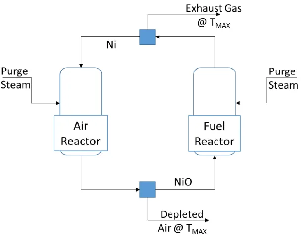
CLC reactor designs have been proposed that convert fuel using an oxidation reactor and a separate reduction reactor, with oxygen carrier in the form of particles circulating pneumatically between the two reactors, as shown schematically in figure 1[20-22]. Thus, in a continuous cyclic process, the oxygen carrier is successively oxidized in the oxidation reactor and reduced in the reduction reactor. A cyclone and a loop seal are used to separate the oxygen carrier particles from the gas streams. These particles are selected based on suitable thermo-physical and kinetic properties like reactivity, oxygen carrying capacity, thermal and thermo-physical stability, resistance to agglomeration and attrition, as well as economic considerations. Typical oxygen carrier particles used in CLC reactors include nickel, copper, iron, manganese and cobalt
[2, 21, 23-25]. Table 1 shows relevant thermal properties and heats of reaction of these materials. The limitations of traditional reactor configurations include large pressure drop due
mostly to particle fluidization, difficulty in maintaining particle circulation at high temperature and pressures, attrition from particle friction, cyclic thermal stresses, agglomeration, particle entrainment and lower CO2 separation efficiency [20, 26, 27]. The fact that the two reactors
operate at different temperatures, particularly when the reduction reaction is endothermic, results in large heat transfer entropy generation, which lowers the overall efficiency.
Other CLC reactor designs have also been proposed, including the moving bed reactor [4, 5] and the fixed packed-bed reactor [28, 29]. In the fixed packed bed setup, the reactor is alternately exposed to reducing and oxidizing conditions via periodic switching of the air and fuel feed streams. This design requires at least two reactors in parallel to ensure continuous exhaust gas supply to the downstream power island. A variation of this design is the SCOT reactor proposed by Chakravarthy et al [30]. This design comprises of at least a pair of packed bed reactors integrated with a system of heat engines interacting with the two reactors, as well as one or more heat pumps. This setup attempts to ensure that the oxidation and reduction reactors mostly take place at or as close as possible to the respective equilibrium temperatures. The internal engine is required to transfer heat from the reactor in the oxidation phase to the reactor in the endothermic reduction phase when the temperature of the solid oxygen carriers start falling below the equilibrium reaction temperature. The heat pump transfers heat to the oxidation reactor when the reaction heat release is insufficient to raise the temperature of the oxygen carrier to the equilibrium (or maximum) oxidation temperature. This setup adds flexibility that enables the reactor to utilize a wider range of oxygen carriers but faces the practical challenge of incorporating an internal heat engine. To overcome the technical challenges related to high temperature gas switching inherent in the fixed bed designs, Dahl &
Hakonsen et al proposed the rotating packed-bed reactor [31, 32]. This reactor consists of a doughnut shaped, fixed oxygen carrier bed rotated between four fixed gas feed sectors on the top face – air sector, fuel sector and two purging sectors to prevent air/fuel mixing. The gas streams flow radially outwards through the bed while reacting with the oxygen carrier. These designs overcome the problem of circulating particles but still accommodate temperature swings between the reduction and the oxidation cycles, increasing reactor entropy generation especially for oxygen carriers with endothermic reduction reactions.
1.2. The Rotary Reactor Design
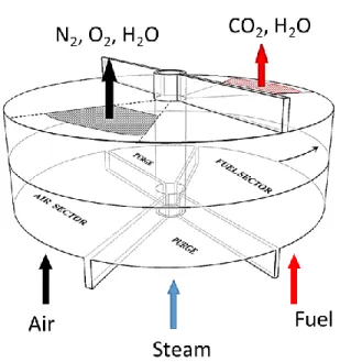
A new rotary reactor design with micro-channel structures proposed by Zhao et al. [1, 2, 33, 34], has the potential to overcome these limitations. This design consists of a solid rotating wheel and two stationary chambers at the inlet and exit sides of the wheel, as shown in figure 2a. The rotating wheel consists of a matrix of micro-channels with the oxygen carrier coated or impregnated on the inner walls of the channels as shown in figure 2b. The channel wall is composed of a dense structural substrate layer and a porous oxygen carrier layer. The inlet chamber is divided into four sectors - fuel, air, and two purging sectors - while the outlet chamber is split into two zones - the air zone, which coincides with the air and air purge sectors, and the fuel zone, which merges the fuel and fuel purge sectors. As the wheel rotates, each
microchannel passes successively through the fuel sector, where fuel enters and reduces the oxygen carrier (exothermic or endothermic reaction); then the fuel purge, where steam sweeps out the exhaust gas from the channel; the air sector where oxygen carrier is oxidized in an air/oxidizing stream (exothermic reaction); and the air purge sector, where steam flushes out
the air prior to re-entering the fuel sector. The combined fuel and fuel purge sector streams leave via the fuel zone while the air and air sector streams leave from the air zone.
During the cyclic operation, the solid wheel also acts as a thermal energy storage medium to transfer the reaction heat between the gas streams and to provide internal thermal coupling between all the sectors in the reactor. The bulk support layer, usually made of high thermal capacity and conductivity material like Boron Nitride, provides this thermal integration. Thermodynamically, this internal thermal coupling can be conceptualized as an infinite series of heat exchangers transferring heat between the air and the fuel reactors at each location along the length of the reactor over an infinitesimal temperature difference. This means that at any axial location, the temperature would be radially uniform; thus the reduction reactions take place at essentially the same temperature as the oxidation reaction. Consequently, the exhaust gases leave the air and fuel zones at nearly the same temperature. The thermal behavior of the rotary reactor based on simulation results by Zhao et al [2] is shown in figure 2c and 2d. It can be seen that the radial temperature variation, which is a measure of the maximum temperature difference between the different sectors in the reactor (fuel, fuel-purge, air and air-purge) is small, with a maximum of less than 30K in the lower part of the reactor and less than 2K at the reactor exit. This effective thermal coupling is possible because the bulk support layer forms a continuous heat conduction path, avoiding the solid-gas-solid and solid-solid contact resistances typical in other reactor designs.
In this paper,”thermal balance” is used to describe the state of thermal coupling in CLC configurations that maintains equilibrium between the fuel and air reactors, creating equal
temperature fuel and airside exhaust streams. It will be shown that thermally balanced reactor operation creates the potential for higher cycle efficiency in CLC power plants.
1.3. Study Objective
This study investigates the integration of the rotary reactor with the power cycle. It presents an analysis of the impact of the thermal coupling on the performance of a CLC energy conversion system in three stages, outlined in Sections 2, 3 and 4. In Section 2, a theoretical availability model, following the approach used by Ritcher et al [3], Chakravarthy et al [30] and McGlashan [35], is used to develop a functional relationship between efficiency and the temperatures of the oxidation and reduction reactors. This is then used to frame the discussion on the relationship between reactor thermal balance and the maximum availability of practical CLC systems, taking into account relevant thermodynamic and material limitations.
Next, the idealizing assumptions are relaxed to accommodate the limitations imposed by specific cycle configurations. Section 3 makes use of an ideal thermodynamic model of a regenerative CLC cycle for this purpose. The expression for the regenerative CLC cycle efficiency as a function of the ratio of reactor temperatures is used to define the relationship between reactor thermal balance and optimal system efficiency. The discussion in this section also covers the implication of thermodynamic and material limitations of practical CLC systems in the context of thermally balanced or imbalanced CLC reactor designs.
In section 4, the thermodynamic idealizations are further relaxed and a higher fidelity Aspen Plus® model of a regenerative CLC cycle introduced in Section 2 is developed. This model provides a more realistic representation of a practical CLC energy conversion system, capturing
the effects of the configurational constraints of a specific cycle. The simulation results are used to validate the conclusions of the previous sections and to quantify the thermal efficiency advantage that results from thermally balanced reactor operation. The Aspen Plus® model is also used to carry out a parametric analysis on the regenerative CLC cycle to determine the impact of key design/operating parameters on system thermal efficiency.
2. Theoretical Availability Analysis
The theoretical availability [36] of a Chemical Looping Combustion (CLC) energy conversion system can provide valuable insight into its efficiency potential. One of the major arguments in favor of CLC is that it is able to achieve complete fuel conversion through a staged reaction process that reduces exergy destruction in the reactor and thus increases the availability of the system [4, 16, 37]. Therefore, the analysis in this section will derive expressions of availability as
a function of reactor temperatures to investigate the impact of reactor thermal coupling on CLC system performance. Note that the following discussion presents conceptual scenarios that broadly define the feasible operating window for CLC energy conversion systems.
In an ideal CLC energy conversion system, all processes have to be reversible. Approaching this reversible limit implies minimizing the entropy generation associated with heat transfer and chemical reaction. To minimize reaction entropy generation, the reaction process should be isothermal and should take place at the equilibrium temperature of the reaction. This equilibrium temperature is determined by setting the change in Gibbs free energy to zero in the classical chemical thermodynamic relation [35, 38].
𝛥𝐺𝑟𝑥𝑛 is the reaction Gibbs free energy, 𝛥𝐻𝑟𝑥𝑛 is the reaction enthalpy, 𝛥𝑆𝑟𝑥𝑛 is the reaction
entropy and 𝑇𝑒𝑞 is the equilibrium temperature of the reaction. The oxidation reaction is
exothermic (∆𝐻𝑜𝑥 > 0). The reduction reaction is typically endothermic (∆𝐻𝑟𝑒𝑑 > 0), but
could also be exothermic. In either case, the sum of the two enthalpies, evaluated at the corresponding reactor temperatures, gives the overall reaction enthalpy (∆𝐻). The enthalpy of reaction depends on the oxygen carrier type as well as the fuel; Take nickel from table 1 for example, the reduction reaction with methane is endothermic while that with hydrogen is mildly exothermic. The oxidation reaction usually occurs at a higher temperature than the reduction reaction. When the reduction reaction is endothermic, the oxidation reaction provides the deficit heat required to sustain this reaction. Modeling the reactors as isothermal heat reservoirs, it is theoretically possible to install a reversible engine (or series of engines) that extracts additional work while interacting with the two reservoirs and the environment. Ritcher and Knoche were the first to present this concept, proposing CLC as a means of improving the availability of fossil fuel systems [3]. This idealized concept has subsequently been developed further by McGlashan [35] and Chakravarthy et al [30] and will serve as the framework for the discussion in this section.
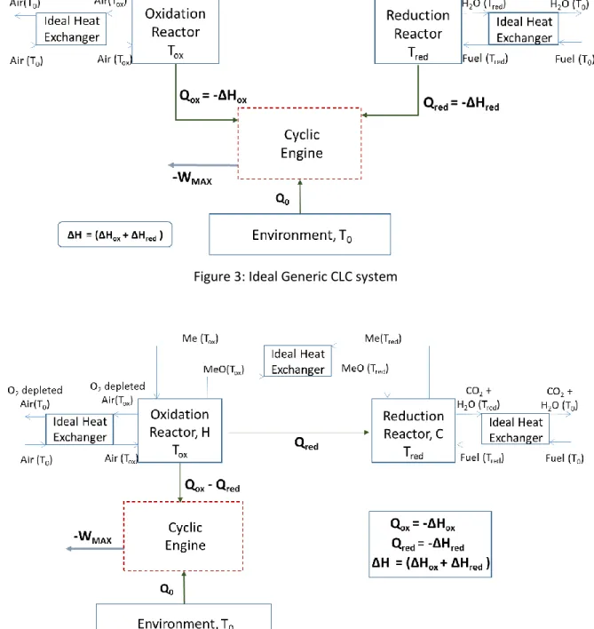
Figure 3 shows an idealized representation of a generic CLC system that consists of an ideal cyclic engine interacting with the oxidation reactor, the reduction reactor and the environment. This setup assumes that the three counter-flow heat exchangers have balanced flows and maintain only an infinitesimal temperature difference between the hot and cold streams. If the reduction reaction is exothermic, the heat release from both reactors is delivered directly to the engine to produce work. For an endothermic reduction reaction, the heat engine transfers
some of the heat from the oxidation reactor to sustain the reduction reaction while producing work. In all cases, both reactors are isothermal and will be treated as thermal reservoirs in the following analysis.
For a system with exothermic reduction reaction, applying the first and second laws of thermodynamics to the cyclic engine control volume gives
−𝑊𝑀𝐴𝑋 = |∆𝐻| (1 − (𝑇0 𝑇𝑜𝑥)) − |∆𝐻𝑟𝑒𝑑| ( 𝑇0 𝑇𝑜𝑥( 𝑇𝑜𝑥−𝑇𝑟𝑒𝑑 𝑇𝑟𝑒𝑑 )) (2)
The same approach for a system with endothermic reduction reaction gives
−𝑊𝑀𝐴𝑋 = |∆𝐻| (1 − (𝑇𝑇0 𝑜𝑥)) + |∆𝐻𝑟𝑒𝑑| ( 𝑇0 𝑇𝑜𝑥( 𝑇𝑜𝑥−𝑇𝑟𝑒𝑑 𝑇𝑟𝑒𝑑 )) (3)
Where 𝑇𝑜𝑥 is the oxidation reaction temperature, 𝑇𝑟𝑒𝑑 is the reduction reaction temperature,
𝑇0 is the environment temperature, ∆𝐻𝑟𝑒𝑑 is the reduction reaction enthalpy, ∆𝐻𝑜𝑥 is the
oxidation reaction enthalpy, −𝑊𝑀𝐴𝑋 is the net work output of the system and the net reaction
enthalpy, ∆𝐻 , is the sum of the oxidation and the reduction reaction enthalpies, given by ∆𝐻 = ∆𝐻𝑜𝑥+ ∆𝐻𝑟𝑒𝑑. The derivation for equations 2 and 3 can be found in Appendix A. The
first term on the right hand side in both expressions is equivalent to the work output of a Carnot engine operating between two reservoirs at the temperature of the oxidation reactor and the environment. The second term constitutes an additional component that modifies the overall system availability, depending on the temperature difference between the two reactors
(𝑇𝑜𝑥𝑇−𝑇𝑟𝑒𝑑
𝑟𝑒𝑑 ). In order to analyze the contribution of this second term to CLC system work output, scenarios for exothermic and endothermic reduction reactions will be considered. Except when
stated otherwise, the following analysis assumes that 𝑇𝑜𝑥 is fixed at its thermodynamic upper
bound, given by the equilibrium temperature of the oxidation reaction defined in equation 1 [30, 35]. 𝑇𝑟𝑒𝑑 is free to take any value within the feasible range for the respective exothermic
or endothermic reactions. The equilibrium reduction reaction temperature defines the lower bound for this range. For the endothermic reduction reaction, the oxidation reaction temperature defines the upper bound.
2.1. Scenario 1: Exothermic Reduction Reaction
Here, ∆𝐻𝑟𝑒𝑑 < 0 while ∆𝑆𝑟𝑒𝑑 > 0, and equation 1 provides an infeasible negative equilibrium
temperature that defines the lower bound. Therefore, theoretically, the reduction reaction temperature can take any value above this lower bound [30]. When 𝑇𝑟𝑒𝑑 ≤ 𝑇𝑜𝑥, maximizing
work output corresponds to minimizing the temperature difference between both reactors, and the maximum availability corresponds to the situation where 𝑇𝑜𝑥 = 𝑇𝑟𝑒𝑑 , in which case
equation 2 becomes
−𝑊𝑀𝐴𝑋 = |∆𝐻| (1 − (𝑇𝑇0
𝑜𝑥)) (4)
Equation 4 defines the availability for the thermally balanced CLC system. Notice that the expression is equivalent to that of an ideal heat engine operating between the oxidation reactor temperature and the environment temperature.
If 𝑇𝑟𝑒𝑑 ≥ 𝑇𝑜𝑥, and 𝑇𝑜𝑥 is fixed at the equilibrium oxidation temperature, then equation 2
suggests that work output increases with increasing difference between the reactor temperatures. In the limit when 𝑇𝑟𝑒𝑑 ≫ 𝑇𝑜𝑥, equation 2 simplifies to equation 5
−𝑊𝑀𝐴𝑋 = |∆𝐻| − (𝑇𝑇𝐸
𝑜𝑥(|∆𝐻𝑜𝑥|)) (5)
In CLC setups with 𝑇𝑟𝑒𝑑 > 𝑇𝑜𝑥 , if the oxidation reactor is at its equilibrium temperature, then
the oxygen carrier leaving the fuel reactor has to be cooled down before the oxidation reaction can proceed. For circulating reactors, this could mean increasing the oxidation reactor residence time to accommodate both the cooling and the reaction phases, or introducing either a heat exchanger or a reformer in-between the two reactors. For packed/fixed bed reactors, one option is to increase oxidation residence time to accommodate cooling and reaction. Another is to have successive reduction and reforming phases in the fuel reactor before switching on the oxidizing stream. These adjustments introduce additional complexity to reactor design and operational management.
However, in practical CLC systems, the maximum reactor temperature is usually constrained below the equilibrium oxidation temperature by the properties of the oxygen carrier, the turbine inlet material or the material of the heat recovery steam generator (HRSG). These material temperature limits impose a more stringent upper bound than the oxidation reactor temperature. Consequently, consistent with the conclusion by Chakravarthy et al [30], 𝑇𝑟𝑒𝑑 can
only be as high as the feasible 𝑇𝑜𝑥 and the maximum work output is obtained at this condition.
The expression for the maximum work output for this condition is the same as in equation 4.
2.2. Scenario 2: Endothermic Reduction Reaction
Here, ∆𝐻𝑟𝑒𝑑 > 0 and ∆𝑆𝑟𝑒𝑑> 0, and the equilibrium temperature determined from equation 1
availability corresponds to maximizing the temperature difference between the two reactors. Thus, maximum work should be obtained when 𝑇𝑟𝑒𝑑 is equal to the equilibrium reduction
temperature, which is the minimum thermodynamically feasible value [30, 35]. This scenario, however, has serious practical challenges. For one, it requires an engine that extracts additional work while transferring heat from the oxidation to the reduction reactor. Realizing such a setup in a real CLC installation may be prohibitively complex. One proposal by McGlashan [35] is the high temperature Rankine cycle using metal vapor working fluid with the oxidation and reduction reactors serving as the boiler and condenser respectively. A steam cycle that uses the condensing metal vapor as heat source could also be added when the heat of condensation is larger than the endothermic enthalpy of reaction. There is, however, the difficulty of finding adequate high temperature materials and managing effective heat transfer involving both gas and solid phase components.
The thermodynamics of an actual design looks more like the representation in figure 4 where the heat is transferred directly from the oxidation to the reduction reactor. In this case, the maximum work output from the CLC system reduces to equation 4, which is the same as that for the thermally balanced reactor configuration. This direct heat transfer also results in increased entropy generation, which can be reduced using thermally coupled reactors to minimize the reactor temperature difference.
Kinetic considerations also play an important role in determining the optimal operating conditions for the reduction reactor. Lower temperatures result in slower kinetics, requiring longer residence times in the reactor. This means larger reactors and higher costs. For this reason, higher temperatures are required to speed up kinetics and favor products formation.
Consequently, the reduction reactor temperature should be as high as possible, with the optimal scenario achieved when 𝑇𝑜𝑥 = 𝑇𝑟𝑒𝑑. To summarize, for a CLC setup with endothermic
reduction reaction, practical considerations exclude the feasibility of installing an engine between the two reactors to extract additional work while reaction kinetics support high reduction reactor temperatures. The optimal operating condition therefore corresponds to the case where the two reactors are in thermal equilibrium. Table 2 summarizes the key conclusions from this section.
3. Thermodynamic Analysis for Idealized Cycles
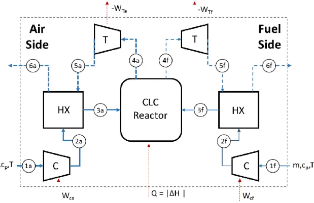
Section 2 used theoretical availability models with Carnot-type engines to analyze the performance limits of CLC systems. This section extends the theoretical analysis to a specific cycle configuration, in this case, an ideal regenerative (Brayton) CLC cycle. A sketch of the
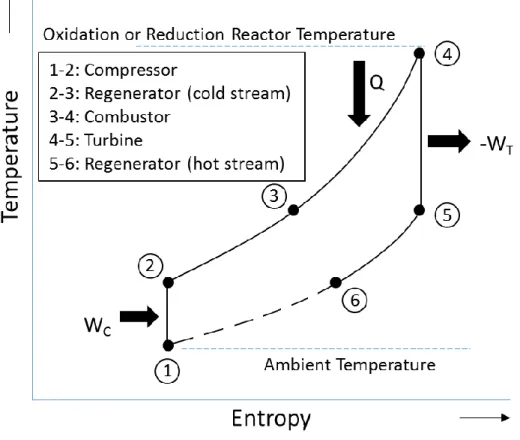
regenerative CLC cycle is shown in figure 5a, while the corresponding T-S diagram represented in figure 5b. This cycle includes a compressor, a combustor, a turbine and a regenerative heat exchanger on both the fuel and the air side (denoted by the subscripts ‘f’ and ‘a’ respectively). On either side, the process path comprises of isentropic compression (1-2), inlet stream preheating in the regenerator (2-3), constant pressure combustion (3-4), isentropic expansion (4-5) and exhaust heat recovery in the regenerator (5-6). The broken line represents the cooling process of the exhaust discharged into the ambient environment. The following analysis assumes that the inlet air and fuel are at ambient temperature and pressure, the heat exchangers are ideal, the thermal capacity (𝑚𝑐𝑝) of the air side and fuel side streams are
therefore, the net heat release (𝑄) in the reactor is constant; The CLC reactor in figure 5a comprises both the oxidation and the reduction reactors. Since the control volume is placed around the reactor, it only captures the net heat release, represented by Q, and does not make a distinction between endothermic or exothermic reduction reactions. The air and fuel side pressure ratios are equal and the turbines and compressors are isentropic. Work (𝑊) and Heat (𝑄) are defined as positive into the control volume, the air side reactor exhaust temperature is
fixed and the air flow rate (𝑚𝑎) is varied to control the fuel side reactor exhaust temperature.
The thermodynamic process for this regenerative cycle is shown in figure 5b. Applying energy conservation on the airside and fuel side components of the regenerative system in figure 5a gives 𝑊𝑁𝑒𝑡𝑎 = 𝑚𝑎𝑐𝑝𝑎𝑇0(𝜋𝛼−𝑇𝑜𝑥 𝑇0
) (1 − 𝜋−𝛼) (6) 𝑊𝑁𝑒𝑡𝑓 = 𝑚𝑓𝑐𝑝𝑓𝑇0(𝜋𝛼−𝑇𝑟𝑒𝑑 𝑇0 ) (1 − 𝜋 −𝛼) (7)
Energy balance on the reactor gives
𝑄 = −Δ𝐻 = (𝑚𝑓𝑐𝑝𝑓𝑇𝑟𝑒𝑑+ 𝑚𝑎𝑐𝑝𝑎𝑇𝑜𝑥) (1 − 𝜋−𝛼) (8)
𝑇𝑜𝑥 is the oxidation reactor temperature, 𝑇𝑟𝑒𝑑 is the reduction reactor temperature, 𝑇0 is the
ambient temperature, 𝑊𝑁𝑒𝑡𝑎 is the net-work output from the air side cycle, 𝑊𝑁𝑒𝑡𝑓 is the
net-work output from the fuel side cycle, 𝑄(−Δ𝐻) is the net reaction enthalpy, 𝑚𝑓 is the fuel side
mass flow rate, 𝑚𝑎 is the air side mass flow rate, 𝑐𝑝𝑓 is the fuel stream specific heat capacity,
equations 6, 7 and 8, one can arrive at an explicit expression for efficiency as a function of reactor temperatures
𝜂 = 1 − 𝑇0( 𝑚𝑓𝑐𝑝𝑓+ 𝑚𝑎𝑐𝑝𝑎)(𝜋𝛼)
( 𝑚𝑓𝑐𝑝𝑓𝑇𝑟𝑒𝑑+ 𝑚𝑎𝑐𝑝𝑎𝑇𝑜𝑥) (9)
𝜂 is the cycle efficiency (See Appendix B for details of the derivation). Now consider the
following cases:
Thermally balanced reactors: the oxidation and reduction reactors are in thermal
equilibrium( 𝑇𝑜𝑥 = 𝑇𝑟𝑒𝑑): Substituting 𝑇𝑜𝑥 = 𝑇𝑟𝑒𝑑 into equation 9, the resulting expression for
the efficiency of the system is given in equation 10. Note that this is the same expression for a conventional (ideal) regenerative Brayton cycle operating over the same temperature range and pressure ratio.
𝜂
𝑡ℎ𝑒𝑟𝑚𝑎𝑙= 1 −
(𝜋𝛼)(𝑇𝑜𝑥𝑇0 )
(10)
Thermal Imbalanced reactors: the oxidation and reduction reactors are not in thermal
equilibrium ( 𝑇𝑜𝑥 ≠ 𝑇𝑟𝑒𝑑) : The relationship between 𝑚𝑎 and 𝑇𝑟𝑒𝑑 means that equation 9 has
only one degree of freedom. Thus, efficiency can be expressed solely in terms of either of these variables. Therefore, substituting for 𝑚𝑎 from equation 8 into equation 9 and rearranging, the
following expression for efficiency is obtained
𝜂 = 1 −( ( 𝑄 (1−𝜋−𝛼)𝑐𝑝𝑎𝑇𝑜𝑥)𝑐𝑝𝑎𝜋𝛼)+(𝑚𝑓𝑐𝑝𝑓𝜋𝛼) (((1−𝜋−𝛼)𝑐𝑝𝑎𝑇𝑜𝑥𝑄 )𝑐𝑝𝑎𝑇𝑜𝑥𝑇0) + (( 𝑚𝑓𝑐𝑝𝑓 𝑐𝑝𝑎 )𝜋𝛼) (((1−𝜋−𝛼)𝑐𝑝𝑎𝑇𝑜𝑥𝑄 )𝑇𝑜𝑥 𝑇0) (𝑇𝑟𝑒𝑑 𝑇𝑜𝑥) = 1 − Ψ1+ Ψ2(𝑇𝑇𝑟𝑒𝑑 𝑜𝑥) (11)
Ψ1 𝑎𝑛𝑑 Ψ2 are positive constants (see Appendix B). Thus the derivative of the cycle efficiency
with respect to the reactor temperature ratio is a positive constant and given by
𝜕𝜂 𝜕(𝑇𝑟𝑒𝑑𝑇𝑜𝑥) = ((𝑚𝑓𝑐𝑝𝑓 𝑐𝑝𝑎 )𝜋𝛼) (((1−𝜋−𝛼)𝑐𝑝𝑎𝑇𝑜𝑥𝑄 )𝑇𝑜𝑥 𝑇0) = Ψ2 (12)
Equation 11 shows that the efficiency for the regenerative CLC system is positively correlated to the reduction/oxidation reactor temperature ratio and maximizing efficiency corresponds to increasing the reduction reactor temperature relative to the oxidation reactor temperature. The derivative of the efficiency with respect to the reduction/oxidation reactor temperature
ratio shows that the slope of a graph of efficiency with respect to this ratio is a positive constant (equation 12).
For an endothermic reduction reaction, in line with the discussion from Section 2, the oxidation reactor temperature constrains the maximum system temperature since heat needs to be transferred from the oxidation to the reduction reaction. Equation 11 shows that increasing the reduction reactor temperature translates to an increase in efficiency. Therefore the maximum efficiency corresponds to the thermally balanced case where 𝑇𝑟𝑒𝑑 = 𝑇𝑜𝑥 and the resulting
expression for efficiency is given in equation 10.
For an exothermic reduction reaction, equation 11 shows that maximum efficiency also corresponds to the thermally balanced case for all values of 𝑇𝑟𝑒𝑑 less than or equal to the
equilibrium temperature of the oxidation reaction. If 𝑇𝑟𝑒𝑑 > 𝑇𝑜𝑥 and 𝑇𝑜𝑥 is fixed at its
equilibrium temperature, then from equation 11, a thermally imbalanced reactor configuration would result in higher efficiency. However, temperature limitations imposed by thermal
properties of the oxygen carriers or turbine material typically define a stricter upper bound for the feasible operating temperature than the oxidation equilibrium temperature. Therefore, 𝑇𝑟𝑒𝑑 can only be as high as the feasible 𝑇𝑜𝑥, and the operating efficiency limit for this case in
practical systems will also correspond to the efficiency defined in equation 10.
In summary, the foregoing analysis has made use of an ideal configuration-specific model to develop an expression for efficiency defined in terms of the reduction/oxidation reactor temperature ratio. Using this expression, and incorporating some knowledge of oxygen carrier properties, as well as process and material constraints, it was shown that the highest efficiency is obtained when both reactors are in thermal equilibrium. Table 3 summarizes the key conclusions from this section.
4. Detailed Thermodynamic Analysis
In Sections 2 and 3, , it was shown that when CLC material and power cycle practical limitations are taken into account, thermally balanced CLC reactor designs have a greater efficiency potential when integrated with idealized power cycles. In this section, a higher fidelity model of the regenerative CLC cycle is developed in Aspen Plus®. This model is used to assess the conclusions about the effect of reactor thermal coupling from the previous sections.
4.1. Model Development and Methodology
4.1.1. Cycle Description
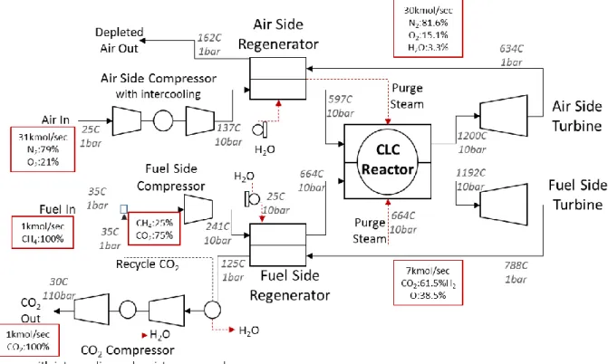
Figure 6 presents a schematic of the Aspen Plus® flow sheet for the rotary CLC regenerative cycle. On the air side, the inlet air is first compressed, then preheated in the regenerator before proceeding to the rotary reactor, where it reacts exothermically with the oxygen carrier.
Compression with intercooling is utilized. The reactor exit is divided into two zones; the air zone, which comprises the air sector and air purge sector of the reactor, and the fuel zone, which contains the fuel sector and fuel purge sector. The air zone exhaust is a mixture of oxygen-depleted air and steam from the air and air purge sectors respectively. The fuel zone exhaust contains the combustion products from the fuel sector (CO2 and H2O) and steam from
the fuel purge sector. The air zone exhaust is expanded for power in the air side turbine. The turbine exhaust is subsequently used for heat recovery in the air side regenerator before being discharged to the atmosphere. The fuel side follows an identical process up till the regenerator. Some of the CO2 from the cool regenerator exhaust stream is recycled to the fuel inlet where it
serves as carrier gas/diluent for the fuel. The remaining CO2 stream is prepared for
sequestration by compressing it up to 110 bars in the CO2 compression unit. This unit delivers
staged compression with intercooling, which also enables the condensation and removal of water vapor from the CO2 stream. The regenerators are also used to generate purge steam for
the air and fuel sectors.
4.1.2. Rotary Reactor Model in Aspen
The rotary reactor design and operation is described in detail in [1, 2, 33, 34]. It is essentially a solid wheel with a matrix of micro channels. The channel walls provide support for the oxygen
carrier, which is coated or impregnated on the inner surface of the micro channels. The solid wall matrix provides structural integrity to the rotary wheel and thermal management for the entire reactor. It should be made from suitable materials which have high mechanical strength, fatigue resistance, thermal capacity and conductivity. The inlet of the reactor is divided into four stationary sectors. Air and fuel are supplied to the air and fuel sectors respectively. Steam
is used in the two purge sectors to prevent any mixing of the air and fuel streams. As the reactor rotates, oxygen is adsorbed while the channels pass through the air sector, and subsequently used to oxidize the fuel in the fuel sector. The solid wheel enables internal thermal coupling, absorbing, transferring and releasing heat as required to ensure that at each point along the reactor axial direction, the different reactor sectors are thermally equilibrated. At the reactor exit, the air and fuel streams are mixed with the corresponding purge steam streams, creating just two separate exhaust streams. The performance of the rotary reactor was evaluated using a one-dimensional plug-flow model with chemistry based on the one-step kinetics developed by Abad et al [25, 39, 40]. Simulation results demonstrated, given sufficient length, complete fuel conversion and CO2 separation, with less than 2K temperature difference
between the fuel and air side reactor exhaust streams.
Based on thermodynamic considerations, the key feature of the rotary reactor design is the internal heat transfer/thermal coupling that maintains the oxidation and reduction reactors in thermal equilibrium [1, 2]. Therefore, to develop a steady state model of this reactor in Aspen Plus®, two operating requirements need to be satisfied. First is that the reactors be at the same temperature or nearly so. The second is that the oxidation reactor exhaust comprise of depleted air and air purge steam while the reduction reactor exhaust contain the combustion products and the fuel purge steam. To simulate this reactor in Aspen Plus®, the setup in figure 7 is used. Two interconnected reactor blocks represent the oxidation and reduction reactors. The oxygen carrier and support material circulate between the reactors, and split blocks are used to model gas-solid separation. For this model, nickel is used as the oxygen carrier, boron nitride as the support material and CH4 as fuel. Since the fuel flow rate is fixed, Ni/CH4 ratio is set at a
fixed value above the stoichiometric amount required for complete conversion of the fuel. The reactors are simulated using the RGibbs model, which determines product phase and composition by minimizing Gibbs free energy. For the sensitivity studies, the oxidation reactor temperature is varied by varying the inlet air flow rate while the reduction reactor temperature is controlled by varying the solid support material circulation rate. To satisfy the second rotary reactor operating requirement, each purge steam is fed directly into the corresponding reactor. This modeling strategy does not reflect the physical design of the rotary reactor since the rotary reactor has no circulating particles. Nevertheless, it captures the objective of representing the thermal coupling in the rotary reactor.
4.1.3. Model specifications
The modeling assumptions and specifications used in developing the base case Rotary Reactor Aspen Plus® system models are summarized in tables 4 and 5. For the reactor model, nickel is chosen as the oxygen carrier with boron nitride as the support material. The base case reactor temperature was set at 1200C because it is in the same temperature range as used in a number of earlier studies [15, 16, 18, 41, 42]. The oxidation reactor temperature is defined as a design specification target and is controlled by varying the inlet air flow rate. The reduction reactor temperature is controlled by varying the boron Nitride circulation rate. A base case operating
pressure of 10 bars is used but is varied between 2 bars and 20 bars for the parametric studies. Pressure drop in the reactor is neglected since the value is very small for the rotary reactor [34]. The CO2 compression unit uses staged compression with intercooling to deliver supercritical
CO2 at 110 bars and 30C to an external CO2 pipeline. Moisture is removed in the intercoolers
4.1.4. Temperature ratio study
In sections 2 and 3, simple thermodynamic models of specific cycles were used to show that the
efficiency of most CLC configurations is a function of the reactor temperature ratio, 𝑇𝑇𝑟𝑒𝑑 𝑜𝑥 , and that under the typical conditions that apply to realistic systems, the highest efficiency was
obtained in reactors when 𝑇𝑇𝑟𝑒𝑑
𝑜𝑥 = 1. This study examines the sensitivity of cycle efficiency to this ratio by varying the reduction reactor temperature from around 800C to the fixed oxidation reactor temperature of 1200C. All other design and operating specifications are as indicated in tables 4 and 5.
4.2. Results
4.2.1. Reactor Temperature Ratio Study
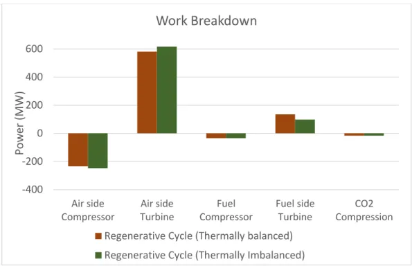
Figure 8 compares the efficiency of a thermally balanced and a thermally imbalanced regenerative CLC cycles at base case conditions. The results show about 54% efficiency for the thermally balanced reactor compared to 52% for the imbalanced design. A work breakdown plot is shown in figure 9 to provide some insight into why this is the case. Compared to the thermally imbalanced case, thermally balanced reactor operation is characterized by a higher reduction reactor temperature, which reduces the airflow required for temperature regulation. The higher reduction reactor temperature leads to increased fuel side turbine output, while the lower air flow rate reduces both the turbine output and the compressor power requirement on the air side, such that the overall effect is a smaller net reduction in air side work output. A close examination of the component contributions to the net system work output shows that the increase in fuel side turbine output is larger than the corresponding decrease on the air side. Consequently, the net effect of thermally balanced reactor operation is an increase in
system efficiency. Therefore, maintaining the reactors in thermal equilibrium increases the availability of the fuel side reactor exhaust stream, leading to higher turbine output and a net increase in system efficiency. Figure 10 relates the ratio of reduction to oxidation reactor
temperatures, 𝑇𝑇𝑟𝑒𝑑
𝑜𝑥 , to the cycle efficiency for the regenerative cycle at different compressor pressure ratios. For each case, efficiency is shown to be a linear function of this ratio, and the slope of the graph is constant as shown in equation 13.
𝛥𝜂 𝛥(𝑇𝑟𝑒𝑑 𝑇𝑜𝑥) = Constant, (𝑇𝑟𝑒𝑑−𝑒𝑞𝑢𝑖𝑙𝑖𝑏𝑟𝑖𝑢𝑚 𝑇𝑜𝑥 ≤ 𝑇𝑟𝑒𝑑 𝑇𝑜𝑥 ≤ 1) (13)
Equation 13, arrived at from the Aspen Plus® model results, is equivalent to equation 12 obtained using the ideal regenerative CLC cycle model. Consequently, these results corroborate the conclusion from sections 2 and 3 that thermally balanced reactors are ideal for maximizing system efficiency. Cycle efficiencies reported in literature for reactor configurations with different degrees of thermal imbalance (𝑇𝑟𝑒𝑑 ranging from 800C to 1100C), methane fuel and
complete CO2 separation range from 47 – 53.5 % [13, 17, 18, 27, 41, 43] for combined cycle CLC
systems. Ishida et al [15] and Brandvoll et al [19] reported efficiencies of 53% and 54% respectively for nickel-based humid air CLC cycles (accounting for CO2 compression). The
configuration presented by Brandvoll et al [19] includes a solid-to-gas heat exchanger between the oxidation and reduction reactors to increase the temperature of the fuel reactor exhaust stream and consequently minimize reactor exergy loss. In the absence of internal thermal coupling, installing a heat exchanger between the two reactors is a good option for improving system availability, though implementing it currently remains technically challenging.
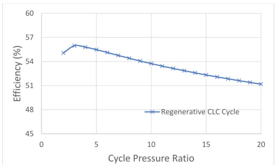
4.2.2. Pressure Sensitivity
The operating pressure has a significant impact on the efficiency of rotary reactor CLC systems. Figure 11 shows the variation of efficiency with pressure for the regenerative cycle configuration. The plot shows a negative proportionality between efficiency and the cycle pressure ratio, consistent with the expression in equation 10. The efficiency peaks at a pressure ratio of about 3 with a value of about 56%. Compressor intercooling is partly responsible for this high efficiency value. It reduces the compression power requirement, and the lower temperature stream leaving the compressor can then recover more heat from the exhaust gas in the regenerator. This maximum efficiency value is clearly higher than efficiencies reported for different CH4-fueled CLC cycle configurations (admitting differences in modeling
assumptions), favoring its selection for CLC power generation. Nevertheless, lower pressures imply higher volumetric gas flow rates, which in turn require larger regenerators and reactors, and may lead to higher costs. A detailed economic evaluation will need to be carried out to more appropriately determine the optimal efficiency/cost trade-off for this configuration.
4.2.3. CO2 fraction sensitivity
Recycled CO2 is normally used as the carrier gas for the fuel which is supplied to the reactor.
This sensitivity study examines the impact of feed stream CO2 fraction on system efficiency by
varying CO2 recycle ratio. In fluid bed CLC designs, feed stream CO2 fraction is determined
mainly by fluidization requirements in the fuel reactor. Since fluidization is not relevant for the rotary reactor, the results from this study could provide an alternative criteria for determining an optimal diluent fraction. The effect of varying the CO2 fraction in the fuel supply stream on
efficiency. Since the fuel side stream leaves the regenerator at a higher temperature than the air side, a mole increase in CO2 results in approximately a mole drop in Air flow requirement for
reactor temperature regulation. The resulting net compressor/turbine work for one mole of the CO2 is larger than the net for an equivalent mole of air for this cycle setup, which is why there is
a resulting positive contribution to net power output as CO2 fraction increases. The optimal
fraction will have to be determined from a tradeoff between efficiency, diffusion resistance and reduction reactor size.
4.2.4. Multivariable parametric study
This study identifies the optimal efficiency region in the space defined by varied design/operating parameter pairs and visualizes the results on surface plots. The parameters considered are operating pressure, CO2 fraction and Turbine Inlet Temperature (TIT). Figure 13
presents the relationship between efficiency, pressure ratio and TIT. For the regenerative CLC cycle, efficiency has an inverse relationship with pressure, independent of TIT. The peak value for TIT of 1000C is 51% at a pressure ratio of 3. This peak pressure does not change much, moving only to 4 bars at 1400C; the efficiency at this point is 60%. In figure 14, efficiency is seen to increase monotonically with CO2 fraction for the entire TIT range considered at 10 bar.
However, efficiency is shown to be a much stronger function of TIT than CO2 fraction. Figure 15
presents an interesting result. At higher pressures, efficiency increases with CO2 fraction, with
up to 1.5% increase when at 15 bars when CO2 fraction is varied from 0.33 to 0.92. The slope of
the efficiency/CO2 fraction curve however decreases continuously till around 4 bars where it flips and becomes negative. Thus, in the 2-4 bar range, lower fractions give higher efficiency at the low pressure ratio range. This increase in efficiency is however very modest; At 2 bar,
efficiency increased by only 0.2% as CO2 fraction varied from 0.92 to 0.33.In summary, for the
regenerative CLC cycle, the optimal operating region is in the low pressure, low CO2 fraction
and high TIT region. Table 6 summarizes the key results from the preceding parametric analysis. The directions of the arrows represent the slopes of the efficiency/parameter curve; upward arrows indicate a positive correlation while downward pointing arrows represent a negative correlation. The results of this study could provide useful input into subsequent optimization studies.
4.2.5. Steam Generation sensitivity
Figures 16 and 17 illustrate the sensitivity of cycle efficiency to the required amount of purge steam generation. The net effect of steam addition is a balance between the energetic cost of producing steam, the additional power output due to the increased reactor exhaust flow and the net contribution from the resulting change in exhaust heat recovery. Figures 16 and 17 show that the impact on efficiency depend on the amount of steam required, the cycle pressure ratio and the turbine inlet temperature. In general, steam generation constitutes a net positive benefit for the regenerative cycle for lower steam requirement because in this range, in addition to increasing the gross exhaust enthalpy, it also improves exhaust heat recovery and minimizes losses to the environment. In the higher range (between 2-3 times fuel flow), the
cost of steam generation becomes the dominant contribution and negatively impacts efficiency. For the rotary reactor, purge steam requirement depends on a number of factors, including reactor temperature, oxygen carrier material and operating pressure. Therefore, optimizing purge steam requirement is an important consideration in designing reactors for integration with energy conversion systems.
4.3. Practical considerations for the rotary CLC reactor-based power plant
4.3.1. Reactor size and Scaling
One of the design challenges for integrating the rotary reactor to a power plant is scaling. Zhao et al presented a detailed discussion of the reactor geometry, kinetics and operating conditions for a rotary reactor [1, 2]. The specifications in table 7 show that for a 1MWthermal capacity, a
reactor of 1m diameter and 0.75m length (~0.6m3) is required. Fundamentally, the reactor thermal capacity scales linearly with its length and quadratically with its diameter, as shown in equations 14 and 15.
𝑀𝑊𝑡ℎ𝑒𝑟𝑚𝑎𝑙 = ( 𝑁 ∗ 𝐷2∗ 𝐿 ) ∗ (𝜋∗ 𝜌 ∗ 𝐿𝐻𝑉 ∗ 𝛳4∗𝜏𝑓𝑢𝑒𝑙 ∗ 𝑥𝑓𝑢𝑒𝑙
𝑎𝑣 ) (14)
Where 𝑀𝑊𝑡ℎ𝑒𝑟𝑚𝑎𝑙 = thermal energy release rate in reactor, 𝑢 = inlet velocity, 𝐷 = reactor
diameter, 𝑁 = number of reactors, 𝜌 = gas density, LHV = lower heating value of fuel, 𝛳𝑓𝑢𝑒𝑙 =
non-dimensional fuel sector size, 𝑥𝑓𝑢𝑒𝑙 = mole fraction of fuel in fuel inlet stream, 𝜏𝑎𝑣 = average
reactor residence time and 𝐿 = reactor length. Therefore,
𝑀𝑊𝑡ℎ𝑒𝑟𝑚𝑎𝑙 ∝ (𝑁 ∗ 𝐷2∗ 𝐿) (15)
Equation 15 shows 3 degrees of freedom for scaling the rotary reactor plant. For example, scaling up to 800MWthermal could be achieved by an array of 16 reactors of 5m diameter and 2m
height, or 64 reactors of 2.5m diameter and 2m height. This approximates to 520m2 and 720m2 of floor space, respectively (assuming vertical axis and 1m spacing in-between reactors) and a total reactor volume of about 470m3. To put this in perspective, an 800MWthermal circulating
fluidized bed plant has a floor area of about 230m2 and reactor volume of approximately 10,000m3 [44]. Though the rotary reactor is significantly more compact than the fluid bed
design, it could require more floor space. Using larger reactors or mounting them on a horizontal axis would require less floor space.
4.3.2. CO2 separation
Another important consideration for the rotary reactor is CO2 separation. To ensure CO2
separation, the reactor sector sizes, rotational speed and purging velocity are selected such that there is enough residence time in the purge sectors for the purge steam to sweep through the reactor length. However, like in industrial rotary heat exchangers, gas leakages between the sectors could arise from pressure difference between the gas streams as well as from the spinning motion of the reactor drum. Fortunately, pressure driven leakages are unlikely in the rotary reactor since all streams are fed at the same pressure. The low rotational speed of the rotary reactor, compared to industrial rotary regenerators, will significantly limit leakage due to reactor spinning motion. In addition, radial seals can be used to limit leakage between stationary insulating walls and the rotating reactor while labyrinth seals and peripheral brush seals could be used to restrict flow bypass [33, 34].
4.3.3. Bulk Support Material Selection
Equally important is material selection for large scale systems. Zhao et al considered Boron nitride as an ideal bulk support material. Although boron nitride has more favorable thermal properties than alternative candidates like beryllium oxide, aluminum nitride, silicon carbide, aluminum oxide and silicon nitride, it is relatively expensive. Selecting the best bulk support option will involve a tradeoff between thermal performance and cost. This highlights the need for a more detailed comparative economic study.
4.3.4. CO2 Turbines
Finally, the model presented includes a high temperature CO2/H2O turbine to produce work
from the fuel side exhaust. CO2 turbines operating around 1200C are under development. A
number of industry collaborative efforts are ongoing to adapt existing turbines so that they accommodate high temperature oxy-fuel exhaust working fluids [45-47]. Future work will incorporate the performance characteristics and limitations of state of the art CO2 turbines in
order to determine the currently feasible performance of the rotary CLC power plant.
5. Conclusion
Starting with a generic availability model, then moving on to a specific ideal thermodynamic model and subsequently, a more rigorous Aspen flow sheet model, this paper has made the case for the advantage of thermally balanced CLC reactor designs for power generation. The availability model was used to show that given typical oxygen carrier properties and material constraints, optimal performance can be obtained if both reactors are maintained in thermal equilibrium. An idealized model of a regenerative CLC cycle was used to confirm this conclusion as well as demonstrate that the system efficiency is proportional to the ratio of the reduction to oxidation reactor temperatures. The detailed Aspen Plus® model of the regenerative CLC cycle confirms this relationship and goes further to specify up to 2% point increase in efficiency resulting from thermally balanced reactor operation in a regenerative CLC cycle. The results from the Aspen Model also indicates that this efficiency advantage comes mainly from the increased availability in the reduction reactor exhaust stream. These results suggest that regenerative power cycles integrated with thermally coupled reactor designs have a distinct
performance advantage, making the rotary CLC reactor design ideal for integration with thermal power plants.
Thermally balanced operation can be approached in traditional fluid bed reactors for oxygen carriers with endothermic reduction reaction, but will require extremely high particle flow rates. Larger oxygen carrier flow rates proportionally increase the size of the reactor, the parasitic power demand and other operational complexities associated with particle circulation. Alternative designs like the packed bed reactor proposed by Noorman [28] or the thermally balanced version of the SCOT process [30], as well as the moving bed reactor [31] are possible options. However, these would require a careful selection of the oxygen carriers, a high inert bed material loading to increase thermal capacity and minimize temperature swings, and fast feed cycling. Increasing bed material loading might result in a non-uniform temperature profile along the reactor due to solid-solid and solid-gas-solid interfacial heat transfer resistances; rapid cycling could inhibit CO2 separation. The rotary reactor design is well suited for thermally
balanced operation. The high thermal capacity and conductivity of the bulk support layer provides the thermal equilibration between the fuel and air sectors along the reactor axial direction. This makes the rotary reactor design ideal for maximizing system efficiency.
Acknowledgement
This study is financially supported by a grant from the MASDAR Institute of Science and Technology and the King Abdullah University of Science and Technology (KAUST) Investigator Award.
Appendices
Appendix A
Applying the first and second laws of thermodynamics to the Carnot engine for the ideal CLC setup in figure 3, the maximum work that can be extracted from the system is obtained as follows: 1st Law 𝑄𝑜𝑥 + 𝑄𝑟𝑒𝑑 + 𝑄0 + 𝑊𝑀𝐴𝑋 = 0 (A1) 2nd Law 𝑄𝑜𝑥 𝑇𝑜𝑥 + 𝑄𝑟𝑒𝑑 𝑇𝑟𝑒𝑑 + 𝑄0 𝑇0 = 0 (A2)
Solving equations A1 and A2, the maximum work output from the system is given by
−𝑊𝑀𝐴𝑋 = 𝑄𝑜𝑥(1 − (𝑇0 𝑇𝑜𝑥)) + 𝑄𝑟𝑒𝑑(1 − ( 𝑇0 𝑇𝑟𝑒𝑑)) (A3) But 𝑄𝑜𝑥 = 𝑄 − 𝑄𝑟𝑒𝑑 (A4)
Substituting into equation A3 and rearranging, we have
−𝑊𝑀𝐴𝑋 = (𝑄 − 𝑄𝑟𝑒𝑑) (1 − (𝑇𝑇0 𝑜𝑥)) + 𝑄𝑟𝑒𝑑(1 − ( 𝑇0 𝑇𝑟𝑒𝑑)) (A5) −𝑊𝑀𝐴𝑋 = 𝑄 (1 − (𝑇0 𝑇𝑜𝑥)) − 𝑄𝑟𝑒𝑑( 𝑇0 𝑇𝑜𝑥( 𝑇𝑜𝑥−𝑇𝑟𝑒𝑑 𝑇𝑟𝑒𝑑 )) (A6)
Case 1: Exothermic Reduction Reaction, Exothermic Oxidation Reaction 𝑄𝑟𝑒𝑑 = | ∆𝐻𝑟𝑒𝑑| (A7) −𝑊𝑀𝐴𝑋 = |∆𝐻| (1 − (𝑇0 𝑇𝑜𝑥)) − |∆𝐻𝑟𝑒𝑑| ( 𝑇0 𝑇𝑜𝑥( 𝑇𝑜𝑥−𝑇𝑟𝑒𝑑 𝑇𝑟𝑒𝑑 )) (A8)
Case 2: Endothermic Reduction Reaction, Exothermic Oxidation Reaction
𝑄𝑟𝑒𝑑 = −| ∆𝐻𝑟𝑒𝑑| (A9) −𝑊𝑀𝐴𝑋 = |∆𝐻| (1 − (𝑇𝑇0 𝑜𝑥)) + |∆𝐻𝑟𝑒𝑑| ( 𝑇0 𝑇𝑜𝑥( 𝑇𝑜𝑥−𝑇𝑟𝑒𝑑 𝑇𝑟𝑒𝑑 )) (A10)
Appendix B
This simplified analysis will consider a regenerative cycle configuration for a CLC system. The schematic representation of a regenerative CLC cycle is shown in figure 5a and the corresponding Temperature-Entropy diagram in 5b. The following assumptions hold for this analysis:
Air and fuel Inlet temperatures and pressures equal to ambient temperature
Ideal heat exchangers (thermally balanced)
Thermal capacity (𝑚𝑐𝑝) for air and fuel side streams constant and independent of
temperature and pressure
Constant heat release (equal to net heat of reaction) in the reactor
Fuel flow rate fixed
Air side and fuel side pressure ratio equal
Air flow rate varies to control fuel side exhaust temperature from the reactor
Work (𝑊) and Heat (𝑄) are defined as positive into the control volume Symbol Definitions 𝑇0 = 𝑇1𝑓 = 𝑇1𝑎 (i) 𝑇𝑜𝑥 = 𝑇4𝑎 (ii) 𝑇𝑟𝑒𝑑 = 𝑇4𝑓 (iii) 𝜋 = 𝑃2 𝑃1 (iv) 𝛼 =( 𝑐𝑝 𝑐𝑣)−1 (𝑐𝑝 𝑐𝑣) (v) 𝑚𝑖𝑐𝑝𝑖= 𝑐𝑜𝑛𝑠𝑡𝑎𝑛𝑡, 𝑖 = 1, … 𝑛 (vi)
Applying the laws of thermodynamics on each of the components (compressors, turbines, heat exchangers and reactor) and taking into account the preceding assumptions, we have the following:
Air side Compressor:
𝑇2𝑎 = 𝑇0(𝜋𝛼) (B1)
𝑊𝑐𝑎 = 𝑚𝑎𝑐𝑝𝑎𝑇0(𝜋𝛼− 1) (B2)
Air side Turbine:
𝑇5𝑎 = 𝑇4𝑎(𝜋−𝛼) = 𝑇
𝑜𝑥(𝜋−𝛼) (B3)
𝑊𝑇𝑎 = 𝑚𝑎𝑐𝑝𝑎𝑇𝑜𝑥(𝜋−𝛼− 1) (B4)
𝑇3𝑎 = 𝑇5𝑎 = 𝑇𝑜𝑥(𝜋−𝛼) (B5)
Fuel side Compressor:
𝑇2𝑓 = 𝑇0(𝜋𝛼) (B6)
𝑊𝑐𝑓 = 𝑚𝑓𝑐𝑝𝑓𝑇0(𝜋𝛼− 1) (B7)
Fuel side Turbine:
𝑇5𝑓 = 𝑇4𝑓(𝜋−𝛼) = 𝑇
𝑟𝑒𝑑(𝜋−𝛼) (B8)
𝑊𝑇𝑓 = 𝑚𝑓𝑐𝑝𝑓𝑇𝑟𝑒𝑑(𝜋−𝛼− 1) (B9)
Fuel side Heat Exchanger
𝑇3𝑓 = 𝑇5𝑓 = 𝑇𝑟𝑒𝑑(𝜋−𝛼) (B10)
CLC Reactor
𝑄 = −Δ𝐻 = (𝑚𝑓𝑐𝑝𝑓𝑇𝑟𝑒𝑑+ 𝑚𝑎𝑐𝑝𝑎𝑇𝑜𝑥) (1 − 𝜋−𝛼) (B11)
Since air mass flow rate is used to control reduction reactor side exit temperature, we derive the expression for mass flow rate
𝑚𝑎 = ((1−𝜋−𝛼𝑄)𝑐 𝑝𝑎𝑇𝑜𝑥− ( 𝑚𝑓𝑐𝑝𝑓 𝑐𝑝𝑎 ) ( 𝑇𝑟𝑒𝑑 𝑇𝑜𝑥)) (B12) 𝑊𝑁𝑒𝑡𝑎 = 𝑊𝑇𝑎+ 𝑊𝑐𝑎 = 𝑚𝑎𝑐𝑝𝑎𝑇0(𝜋𝛼−𝑇𝑜𝑥 𝑇0) (1 − 𝜋 −𝛼) (B13) 𝑊𝑁𝑒𝑡𝑓 = 𝑊𝑇𝑓+ 𝑊𝑐𝑓 = 𝑚𝑓𝑐𝑝𝑓𝑇0(𝜋𝛼−𝑇𝑟𝑒𝑑 𝑇0 ) (1 − 𝜋 −𝛼) (B14)
𝜂 = −
𝑊𝑁𝑒𝑡𝑎+ 𝑊𝑁𝑒𝑡𝑓𝑄 (B15)
𝜂 = 1 −
( 𝑚𝑓𝑐𝑝𝑓+ 𝑚𝑎𝑐𝑝𝑎)(𝜋𝛼)( 𝑚𝑓𝑐𝑝𝑓(𝑇𝑟𝑒𝑑𝑇0 )+ 𝑚𝑎𝑐𝑝𝑎(𝑇𝑜𝑥𝑇0))
(B16)
Case 1: Oxidation and reduction reactor in thermal equilibrium ( (𝑇𝑇𝑟𝑒𝑑
𝑜𝑥) = 1)
Therefore, equation B16 reduces to
𝜂 = 1 − (𝜋𝛼)
(𝑇𝑜𝑥
𝑇0)
(B17)
Case 2: oxidation and reduction reactor not in thermal equilibrium ( (𝑇𝑇𝑟𝑒𝑑
𝑜𝑥) ≠ 1)
From equation B12, the mass flow rate is a linear function of (𝑇𝑇𝑟𝑒𝑑
𝑜𝑥) and can be written as
𝑚𝑎 = (Ψ1− Ψ2(𝑇𝑟𝑒𝑑 𝑇𝑜𝑥)) (B18) Where Ψ1 = ( 𝑄 (1−𝜋−𝛼)𝑐𝑝𝑎𝑇𝑜𝑥) = 𝑐𝑜𝑛𝑠𝑡𝑎𝑛𝑡 (B19) Ψ2 = ((𝑚𝑐𝑓𝑐𝑝𝑓 𝑝𝑎 )) = 𝑐𝑜𝑛𝑠𝑡𝑎𝑛𝑡 (B20)
Substituting (B18) into (B16) and rearranging, we have that
𝜂 = 1 −( ( 𝑄 (1−𝜋−𝛼)𝑐𝑝𝑎𝑇𝑜𝑥)𝑐𝑝𝑎𝜋𝛼)+(𝑚𝑓𝑐𝑝𝑓𝜋𝛼) (((1−𝜋−𝛼)𝑐𝑝𝑎𝑇𝑜𝑥𝑄 )𝑐𝑝𝑎𝑇𝑜𝑥𝑇0) + (( 𝑚𝑓𝑐𝑝𝑓 𝑐𝑝𝑎 )𝜋𝛼) (((1−𝜋−𝛼)𝑐𝑝𝑎𝑇𝑜𝑥𝑄 )𝑇𝑜𝑥 𝑇0) (𝑇𝑟𝑒𝑑 𝑇𝑜𝑥)
𝜂 = 1 − Ψ1+ Ψ2(𝑇𝑟𝑒𝑑 𝑇𝑜𝑥) (B21) Where Ψ1 = ( ((1−𝜋−𝛼)𝑐𝑝𝑎𝑇𝑜𝑥𝑄 )𝑐𝑝𝑎𝜋𝛼)+(𝑚𝑓𝑐𝑝𝑓𝜋𝛼) (((1−𝜋−𝛼)𝑐𝑝𝑎𝑇𝑜𝑥𝑄 )𝑐𝑝𝑎𝑇𝑜𝑥𝑇0) = 𝑐𝑜𝑛𝑠𝑡𝑎𝑛𝑡 (B22) Ψ2 = ((𝑚𝑓𝑐𝑝𝑓 𝑐𝑝𝑎 )𝜋𝛼) (( 𝑄 (1−𝜋−𝛼)𝑐𝑝𝑎𝑇𝑜𝑥)𝑇𝑜𝑥𝑇0) = 𝑐𝑜𝑛𝑠𝑡𝑎𝑛𝑡 (B23)
References
[1] Zhao, Z., Iloeje, C. O., Chen, T., Ghoniem, A. F., Design of a rotary reactor for chemical-looping combustion. Part 1: Fundamentals and design methodology, Fuel, 2014, 121, 327-343.
[2] Zhao, Z., Ghoniem, A. F., Design of a rotary reactor for chemical-looping combustion. Part 2: Comparison of copper-, nickel-, and iron-based oxygen carriers, Fuel, 2014, 121, 344-360.
[3] Ritcher, J. R., Knoche, K. F., Reversibility of Combustion Processes, ACS Symposium Series, 1983, 71-85.
[4] Fan, L., Fanxing, L., Chemical Looping Systems for Fossil Energy Conversions, John Wiley & Sons, Inc., Hoboken, New Jersey, USA, 2010.
[5] Li, F., Zeng, L., Velazquez-Vargas, L. G., Yoscovits, Z., Fan, L., Syngas chemical looping gasification process: Bench-scale studies and reactor simulations, AIChE J., 2010, 56, 2186-2199.
[6] Mattisson, T., Lyngfelt, A., Applications of Chemical-Looping Combustion with Capture of CO2, In Proc. 2nd Nordic Mini-symposium on Carbon Dioxide Capture and Storage,
[7] Ortiz, M., Abad, A., de Diego, L. F., García-Labiano, F., Gayán, P., Adánez, J. , Optimization of hydrogen production by Chemical-Looping auto-thermal Reforming working with Ni-based oxygen-carriers, Int. J. Hydrogen Energy, 2011, 36, 9663-9672.
[8] Rydén, M., Lyngfelt, A. , Using steam reforming to produce hydrogen with carbon dioxide capture by chemical-looping combustion, Int. J. Hydrogen Energy, 2006, 31, 1271-1283. [9] Rydén, M., Lyngfelt, A., Mattisson, T., Two Novel Approaches for Hydrogen Production,
Chemical-Looping Reforming and Steam Reforming with Carbon Dioxide Capture by Chemical-Looping Combustion, In Proc. 16th World Hydrogen Energy Conf. (WHEC), Lyon, France, 2006.
[10] Rydén, M. , Hydrogen Production with Fossil Fuels with Carbon Dioxide Capture, using Chemical-Looping Technologies, Chalmers University of Technology, Göteborg, Sweden, 2008.
[11] Wolf, J., Yan, J., Cogeneration of Hydrogen and Electrical Power in an Extended
Chemical-Looping Combustion, In Proceedings of ECOS 2004, Guanajuato, Mexico, 2004, . [12] Behdad, M., Application of Chemical Looping Concept for Air Separation at High
Temperatures, Energy Fuels, 2010, 190-198.
[13] Kvamsdal, H. M., Jordal, K., Bolland, O. , A quantitative comparison of gas turbine cycles with capture, Energy, 2007, 32, 10-24.
[14] Ishida, M., Zheng, D., Akehata, T., Evaluation of a chemical-looping-combustion power-generation system by graphic exergy analysis, Energy, 1987, 12, 147-154.
[15] Ishida, M., Jin, H., A new advanced power-generation system using chemical-looping combustion, Energy, 1994, 19, 415-422.
[16] Anheden, M., Svedberg, G., Exergy analysis of chemical-looping combustion systems, Energy Conversion and Management, 1998, 39, 1967-1980.
[17] Naqvi, R., Wolf, J., Bolland, O. , Part-load analysis of a chemical looping combustion (CLC) combined cycle with CO2 capture, Energy, 2007, 32, 360-370.
[18] Naqvi, R., Bolland, O. , Multi-stage chemical looping combustion (CLC) for combined cycles with CO2 capture, International Journal of Greenhouse Gas Control, 2007, 1, 19-30.
[19] Brandvoll, O., Bolland, O. , Inherent CO2 Capture using chemical looping combustion in a
![Figure 2c: Axial temperature Profile in Reactor Channel. Dotted line shows maximum radial temperature variation at each axial node [1, 2]](https://thumb-eu.123doks.com/thumbv2/123doknet/13980556.454270/44.918.198.705.475.873/figure-temperature-profile-reactor-channel-dotted-temperature-variation.webp)
![Figure 2d: Solid temperature deviation versus time (Radial location) within one cycle for a nickel-based rotary Reactor [2]](https://thumb-eu.123doks.com/thumbv2/123doknet/13980556.454270/45.918.148.777.120.706/figure-solid-temperature-deviation-versus-radial-location-reactor.webp)