يملعلا ثحبلاو يلاعلا ميلعتلا ةرازو
Ministère de l'Enseignement Supérieur et de la Recherche Scientifique
سيداب نب ديمحلا دبع ةعماج
مناغتسم
Université Abdelhamid Ibn Badis Mostaganem
ايجولونكتلاو مولعلا ةيلك
مناغتسم
Faculté Des Sciences et de la Technologie Mostaganem
Mémoire De Fin D’Etude De Master Académique
Filiere : Electronique
Spécialité : Systemès des télécommunications
Thème
MPLS (
Multi prortocol Label Switching
) Applications
Présenté par : DELMI Youssouf
Membres du jury :
Président : Mme BENCHELLAL Amel Examinateur 1 : Mme BECHIRI Fatiha Encadreur : Mr RESFA Abbes
i
Acknowledgment
Nous adressons en premier notre Seigneur ALLAH qui nous a donné la force et la détermination afin d’élaboré ce modeste travail.
Nous tenons tout d’abord à remercier Mr RASFA Abbes notre encadreur de mémoire, pour tout
le soutien, l’aide, l’orientation, la guidance qu’elle nous a apportés durant le mémoire, ainsi que pour ses précieux conseils et ses encouragements lors de la réalisation de notre mémoire.
Nous remercions vivement le président de jury Mme BENCHELLAL Amel ansi que les Membres du jury Mme BECHIRI Fatiha d’avoir accepté d’évaluer notre travail. Nous tenons ensuite à remercier nos chers parents qui nous ont enseigné la patience, la politesse, le sacrifice et qui nous ont supportés sans condition jusqu’à l’arrivée de ce jour
ii
Dedication
J’ai l’honneur de dédier ce mémoire :À l’homme, mon précieux offre du dieu, mon exemple éternel, mon soutien moral, celui qui s’est toujours sacrifié pour me voir réussir, à toi mon cher père.
À ma chéri, ma vie, ma source de joie et de force qui a toujours été à mes côtés pour me soutenir et m’encourager, maman que j’adore.
À mes chers frères Abd Aziz, Amine. À ma chers Tante Rouba.
À ma très chère grande mère pour son Douaa tout au long de ma vie, que dieu vous préserve la bonne santé et longue vie.
iii
Abstract
This thesis will describe MPLS networks and explain the need for such technology as well as its contribution to networking in general.
We focused on its major applications, how it can provide WAN connectivity between remote sites in a scalable way by implementing MPLS VPN, how we can optimize network infrastructure usage and manually prioritize traffic based on its nature within the MPLS network via TE and QoS.
Finally, we deployed all the previous features separately in order to make our knowledge more tangible, for that we used GNS3 to get the closest results to real-world implementations, alongside WireShark to capture pertinent packets for demonstration purposes.
Keywords: IP, VPN, MPLS, TE and QoS.
Résumé
Cette mémoire explique la technologie MPLS et sa nécessité dans les réseaux à grandes dimension, ainsi que ses applications principales afin de fournir une connectivité WAN entre les sites distants grâce à l’implémentation d’une architecture MPLS VPN, la manière d’optimiser l’utilisation d’une infrastructure réseau et comment tracer manuellement le trafic au sein d’un réseau MPLS via TE et QoS.
Enfin, l’implémentation a été réalisée au moyen de simulateur GNS3 sur différentes topologie de réseau, et les tests en utilisant wireshark afin de capturer les paquets tout au long du chemin. Les mots clés : IP, MPLS, VPN et QoS.
iv
صخلم
ووووووووووووووو يووووووووووووووو لاوووووووووووووووع ووووووووووووووووس
ة ووووووووووووووولما
ووووووووووووووول ةوووووووووووووووجاحلا ووووووووووووووو و وووووووووووووووو وتو لا ددوووووووووووووووعتم مووووووووووووووووسولا رشدوووووووووووووووبت ةوووووووووووووووينقت
وووووووووووو
و ةيوووووووووووووس لا اوووووووووووووق اقيب ت وووووووووووو ع اووووووووووووون ر ماوووووووووووووع ر وووووووووووو اووووووووووووو ت يووووووووووووو اقيم اووووووووووووسم عل ووووووووووووو و ةوووووووووووووينقتلا
وووووووووووووي
ةيوووووووووووووووو ا ةوووووووووووووووو اخلا ا بوووووووووووووووو لا اوووووووووووووووو تا وووووووووووووووووت بش نووووووووووووووووكمش
ةوووووووووووووووووي بلا ماد تووووووووووووووووسا ب ووووووووووووووووسحت اووووووووووووووووننكمش ووووووووووووووووي ،
ةكبووووووووووووووو لا رووووووووووووووو اد اوووووووووووووووقيعيب ووووووووووووووو ع نا وووووووووووووووكت م ااودوووووووووووووووش اووووووووووووووونايبلا ةووووووووووووووو اووووووووووووووواولوش دوووووووووووووووشدحتو ةكبووووووووووووووو لل ةووووووووووووووويتحتلا
مدوووووووووووووووخلا ةدووووووووووووووووج وووووووووووووو ع
روووووووووووووووعج روووووووووووووووجش نووووووووووووووم رووووووووووووووو نم ر ووووووووووووووو ةقباووووووووووووووسلا ا ووووووووووووووو لما نووووووووووووووويمج اوووووووووووووويب تب انمق،ا ش ا
يكاوووووووووووووووووحم انمد تووووووووووووووووووسا عل وووووووووووووووووول ، ةوووووووووووووووووويقيب ت وووووووووووووووووو ش اووووووووووووووووونت عم
(GNS3)
اووووووووووووووووووقيب تل اووووووووووووووووووتنلا وووووووووووووووووو ع ووووووووووووووووووو حلل
ةن لا ض غل ةل لا اذ انايبلا رلحم نم بنج ل ابنج ، يعقاولا ملاعلا
وووووووووووووووووووووووووو وتو لا ددوووووووووووووووووووووووووعتم مووووووووووووووووووووووووووسولا رشدوووووووووووووووووووووووووبت ةوووووووووووووووووووووووووي ات لما اووووووووووووووووووووووووومل لا
(MPLS)
ةووووووووووووووووووووووووو اخلا ا بووووووووووووووووووووووووو لا،
ةي ا الا
(VPN)
امدخلا ةدوج،
(QoS)
1
Introduction
Telecommunications networks are continually expanding, and new technologies are being developed. The old packet management mechanisms are now redundant due to the latest service prerequisite
As the networks grows in size, the routers become very busy working with routing tables based on IP prefixes. In addition, routers decide the shortest path between the source and destination, and when all the traffic is sent through the shortest path, it can create congestion in the network. In order to deal with this, new mechanisms to improve the networks are needed.
On the other hand, real time traffic requires certain guarantees. When real time traffic is sent through a network, it has to share the resources with other traffic types, and does not get enough resources to be routed without delay, jitter and congestion problems.
Mpls network can provide an interconnected environment to create a converging network capable of delivering QoS and traffic engineering services. Most companies are developing their newest networks, built with mpls, and moving the older ones to mpls. also, it is considered that MPLS can provide a better support to the QoS. The network configured with MPLS can be used to handle performance factors of the network in a better way as compared to just IP routing.
2
Content
Acknowledgment ... i Abstract ... iii Introduction ... 1 MPLS ... 10 1.1 Introduction ... 11 1.2 MPLS Technology ... 111.3 Label Forwarding Logic ... 11
1.4 Label Distribution Protocol ... 12
1.5 Information Base Structures ... 15
1.6 MPLS Labels ... 16 1.6.1 Label stacking ... 16 1.6.2 MPLS Encapsulation ... 17 1.7 Conclusion ... 17 MPLS VPN ... 18 2.1 Introduction ... 19 2.2 Control Plane ... 20 2.3 MPBGP Instances ... 21
2.3.1 Virtual Routing Forwarding ( VRF ) ... 21
2.3.2 Route Distinguisher (RD) ... 22
2.3.3 Route Target (RT) ... 23
2.4 PE-CE Routing ... 24
2.4.1 Ingress PE-CE Routing ... 25
2.4.2 Egress PE-CE Routing ... 25
2.5 PE-PE Routing ... 26
2.6 Data plane ... 27
2.7 Overlapping VPN ... 29
2.8 Conclusion ... 30
3 3.1 Introduction ... 32 3.2 TE Link Attributes ... 32 3.3 TE Information distribution ... 33 3.4 OSPF-TE Adaptation ... 34 3.4.1 OSPF-TE Advertisements ... 34
3.5 MPLS-TE Tunnels (Attributes and Path calculation PCALC) ... 36
3.6 RSVP Tunnel Establishment (RSVP) ... 38
3.6.1 Enabling TE Tunnels ... 39
3.7 MPLS VPN Adaptation ... 40
3.7.1 PE-PE Routers Tunnel ... 40
3.7.2 PE (or P)-P Tunnel ... 41
3.8 Conclusion ... 42
MPLS Quality of Service ... 43
4.1 Introduction ... 43
4.2 End to End Qos Models ... 44
4.3 Quality of Service Tools ... 44
4.3.1 Classification and Marking ... 44
4.3.2 Congestion-Management ... 47
4.3.3 Congestion Avoidance ... 49
4.3.4 Shaping and Policing ... 51
4.4 MPLS DiffServ Tunneling Modes ... 51
4.4.1 Uniform Model ... 52
4.4.2 Pipe Model ... 52
4.4.3 Short Pipe Model ... 53
4.5 Conclusion ... 53
MPLS ApplicationsDeployment ... 54
5.1 The work environment ... 55
5.1.1 Choice of software ... 55
5.1.2 Choice of material ... 56
5.2 MPLS VPN Lab ... 57
4
5.2.2 MPLS Verification ... 58
5.2.3 PE-PE Configuration ... 59
5.2.4 PE-PE Verification ... 60
5.2.5 PE-CE Configuration ... 61
5.2.6 Adding Centralized Servers... 65
5.2.7 Wireshark Captures ... 66 5.3 MPLS TE Lab ... 69 5.3.1 MPLS Configuration ... 70 5.3.2 MPLS TE Configuration ... 70 5.3.3 Tunnels Configuration ... 71 5.3.4 Tunnels Verification ... 73 5.3.5 Traffic Forwarding ... 74
5.3.6 Traffic Forwarding Verfication ... 75
5.3.7 Wireshark Captures ... 76
5.4 MPLS QoS Lab ... 78
5.5 MPLS QoS configuration ... 78
5.5.1 CE 1 configuration ... 78
5.5.2 IP to MPLS Domain Configuration ... 80
5.5.3 Pop label operation ... 81
5.5.4 MPLS to IP domain configuration ... 82 5.5.5 CE 2 Configuration ... 84 5.6 QoS Verification ... 85 5.7 Conclusion ... 89 General conclusion ... 90 Perspectives ... 90 Bibliography ... 91
5
List of Figures
Figure 1.1: MPLS Forwarding Model ... 11
Figure 1.2 : LDP Labels Creation and Distribution ... 13
Figure 1.3: LDP Features ... 13
Figure 1.4: LDP Hello Message ... 14
Figure 1.5: Labels 10-25 LSP ... 14
Figure 1.6: Different Information Base Structures ... 15
Figure 1.7: MPLS Header ... 16
Figure 1.8: Label stack ... 17
Figure 1.9: MPLS Header Placement ... 17
Figure 2.1: MPLS VPN Architecture ... 19
Figure 2.2: MPLS VPN Control Plane Protocols ... 20
Figure 2.3: VRF Process ... 21
Figure 2.4: IGP to BGP VPNv4 Routes Exportation ... 23
Figure 2.5: Routes Exportation and Importation ... 24
Figure 2.6: Ingress PE-CE Routing Process Overview ... 25
Figure 2.7: Egress PE-CE Process Overview ... 26
Figure 2.8: PE-PE Operations Steps ... 26
Figure 2.9: MPLS VPN Traffic Forwarding Paradigm ... 28
Figure 2.10: Penultimate Pop Hopping ... 28
Figure 2.11: Overlapping VPN Design Example ... 29
Figure 3.1: IGP-TE Update Triggers Thresholds ... 35
Figure 3.2: RSVP-TE Operations ... 39
Figure 3.3: PE1-PE2 Tunnel Path ... 40
Figure 3.4: P1-P3 Tunnel Path ... 41
Figure 3.5: P-P Tunnel Data plane Overview [2] ... 42
Figure 4.1: IP Precedence ToS in an IP Packet Header ... 45
Figure 4.2: DiffServ with IP packets ... 45
Figure 4.3: DiffServ with MPLS Packets ... 46
6
Figure 4.5: WRED Graph ... 50
Figure 4.6: uniform model ... 52
Figure 4.7: pipe model ... 52
Figure 4.8: short pipe model ... 53
Figure 5.1: GNS3 Emulator ... 55
Figure 5.2 : Wireshark network protocol analyzer ... 56
Figure 5.3: Crossover cable ... 56
Figure 5.4: Serial cable ... 56
Figure 5.5: Cisco C7200 router ... 57
Figure 5.6: MPLS VPN Topology ... 57
Figure 5.7: LDP Bindings ... 59
Figure 5.8: Traceroute Output ... 59
Figure 5.9: BGP Adjacency ... 60
Figure 5.10: PE2 BranchA-VRF Routing Table Entry ... 62
Figure 5.11: BranchB Site2 Routing Table ... 64
Figure 5.12: BranchA Site2 Routing Table ... 64
Figure 5.13: BranchA-VRF Routing Table on PE1 ... 64
Figure 5.14: BranchA-VRF Routing Table on PE1 ... 66
Figure 5.15: BGP OPEN Message ... 67
Figure 5.16: BGP Update ... 67
Figure 5.17: BGP Extended Communities ... 67
Figure 5.18: NLRI Information ... 68
Figure 5.19: LDP Hello Messages ... 68
Figure 5.20: LDP Label Mapping ... 68
Figure 5.21: CE-CE ICMP Request on PE1-P1 Link ... 69
Figure 5.22: CE-CE ICMP Request on P1-P2 Link ... 69
Figure 5.23: MPLS TE Topology ... 69
Figure 5.24: Tunnel1 Status ... 73
Figure 5.25: Tunnel2 Status ... 73
Figure 5.26: TE Tunnels Status ... 73
7
Figure 5.28: Tunnel2 Explicit Path ... 74
Figure 5.29: Traceroute Output ... 74
Figure 5.30: Traceroute Output ... 75
Figure 5.31: Traceroute Output ... 75
Figure 5.32: Tunnel2 Path Change History ... 76
Figure 5.33: OSPF LSU ... 76
Figure 5.34: Link Information ... 76
Figure 5.35: RSVP PATH Message ... 77
Figure 5.36: RSVP RESV Message ... 77
Figure 5.37: ICMP Request on R1-R2 Link ... 77
Figure 5.38: ICMP Request on R1-R2 Link ... 78
Figure 5.39: MPLS QoS Topology ... 78
Figure 5.40: Ping IP Precedence 1 ... 86
Figure 5.41: EXP Information 1 ... 86
Figure 5.42: EXP Information 3 ... 87
Figure 5.43: EXP Information 3 ... 87
Figure 5.44: EXP Information 5 ... 87
Figure 5.45: EXP Information 5 ... 88
Figure 5.46: PE1 Policy-map Information ... 88
Figure 5.47: P1 Policy-map Information ... 88
Figure 5.48: PE2 Policy-map Information ... 88
8
List of Abbreviations
ATM Asynchronous transfer mode ACL Access List
BGP Border gateway Protocol CE Customer edge
CEF Cisco Express Forwarding CSPF Constrained Shortest Path First DSCP Differentiated Services Code Point EGP Exterior getway protocol
EIGRP Enhanced Interior Gateway Routing Protocol ERO Explicit Route Object
ERP Entreprise resource planning EXP Experimental
FIB Forwarding information base HDLC Level Data Link Control IGP Interior getway protocol LFIB Label Forwarding Info Base LDP Label Distribution Protocol LSR Label Switch Router LSA Link-state advertisement
MPBGP Multi-Protocol Border gateway Protocol MPLS Multi protocol label switching
NLRI Network Layer Reachability Information OSPF Open shortest path Firset
9 PE Provider edge
QoS Quality of services
RIP Routing Information Protocol RSVP Resource Reservation Protocol SLA Service-level agreement TE Traffic Engineering
TED Traffic Engineering Database TLV Type Length value
ToS Type of service VoIP Voice over IP
VPN Virtual Protocol Network WAN Wide area network
10
Chapter 1
MPLS
In this opening chapter, we will dive into the MPLS technology, from its evolution to its main operations; we will discuss it from both a control and a data plane standpoint.
11
1.1 Introduction
1.2 MPLS Technology
MPLS is a set of protocols that create a new paradigm of how routers forward packets. Instead of forwarding packets based on the IP addresses, MPLS introduces a new way to define packet routes, which is the MPLS label, which changes on a per-hop basis, which allows MPLS to have various factors to influence the packet forwarding mechanism and such as: QoS requirements, the ability to provide privacy for multiple customers connected to the same MPLS network and traffic engineering, which will be discussed further in the upcoming chapters [7] .
1.3 Label Forwarding Logic
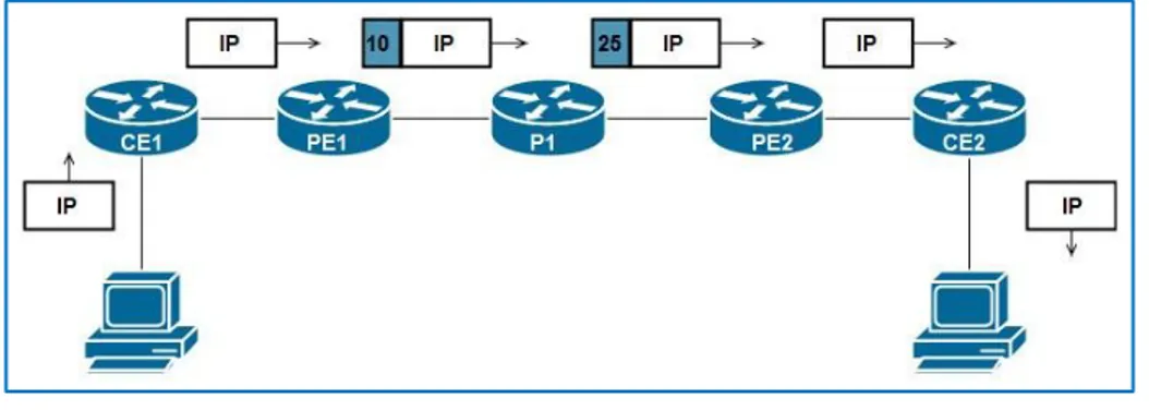
The MPLS forwarding model uses labels in order to transmit packets in the MPLS network. Once the packet enters the MPLS network, an LSR ( Label Switch Router) which represents any router that is MPLS aware, imposes a label corresponding to the destination IP address after a FIB (Forwarding Information Base) lookup and then forwards it as a labeled packet through the MPLS network until it reaches the egress router in the MPLS network, which will pop the label and forward the unlabeled packet, thus the host and the recipient of the packet do not necessarily need to have any awareness about MPLS whatsoever, the example below demonstrates the process:
12
In a typical MPLS network, we can discern three types of LSRs, namely:
• Ingress LSR (PE1): It is an LSR that receives an unlabeled packet, then pushes a corresponding label and forwards it.
• Intermediate LSR (P): It is a router that is found within the MPLS network and it processes labeled packets only.
• Egress LSR (PE2): It is an LSR that receives a labeled packet, then pops all the labels and forward it as an unlabeled packet [1].
1.4 Label Distribution Protocol
In order for IP routing to work, we need a control plane protocol to populate the routing table and allow the packets to be forwarded, which is one of the Interior Gateway Protocols (IGP) or Border Gateway Protocol (BGP), however in MPLS, we need an IGP and another control plane protocol in order to populate the Label Forwarding Info Base (LFIB) which is the Label Distribution Protocol (LDP), the next point explain the process of MPLS unicast IP forwarding:
1. The router creates local labels for each IP routing table (FIB) entry from its label range once MPLS is enabled.
2. LDP is enabled and starts multicasting UDP Hello packets to 224.0.0.2 in order to discover and form a neighborship with connected LSRs, note that a router needs a route to the IP address used as an LDP router-id in the remote router.
3. Once Hellos are mutually exchanged, a TCP 3-way handshake is established and the neighborship is up.
4. The neighbors LSRs start exchanging their IP Address-to-Label mappings found in their respective LFIB.
5. Once an eLSR learns a new IP route through its IGP, it allocates a new local label and triggers an LDP update to its neighbors [11].
13
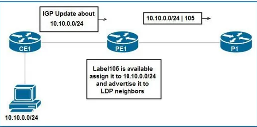
Figure 1.2 : LDP Labels Creation and Distribution
Now, once P1 receives the (10.10.0.0/24|105) binding, it will store it in its LFIB and will create a local binding for 10.10.0.0/24 then advertise it to its neighbors and so on and so forth until every LSR has a local binding for 10.10.0.0/24 and remote bindings advertised by neighbors [4].
This following table covers all LDP features:
Figure 1.3: LDP Features
However, we must note that the hello packets are sourced from the physical ports, carrying a transport address and the LSR ID, as the figure 1.4 demon-states:
14
Figure 1.4: LDP Hello Message
These transport addresses are used to form the TCP connection between the two LSRs, instead of using the physical addresses, note that a mutual connectivity between these two transport addresses is mandatory to instruct the TCP session, it is also configurable through the CLI, The LDP identifier (LDP ID) is used to uniquely identify the neighbor Now that the entire MPLS network is up to date, an MPLS Label Switched Path (LSP) is the sequence of labels that must be used to forward the packets correctly to the destination. For exemple, Figure 1.5 demonstrates the (10-25) LSP [4].
Figure 1.5: Labels 10-25 LSP
We know that in order to populate the routing table in an IP network, we use an IGP such as OSPF, EIGRP Etc. In case of multiple routes to the same destination, we resort to either the Metric or the Administrative Distance in case those routes are provided by the same IGP or multiple IGPs respectively, in order to pick the best routes and add them to the FIB, however, there’s no such feature in MPLS to define the best path, that is why MPLS depends on the
15
existing IP network in order to make forwarding decisions, by choosing the LDP peer that has the destination network next hop address bound to it.
1.5 Information Base Structures
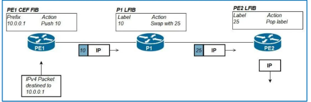
In order to forward packets the LSRs either use the Forwarding Info Base ( FIB ) or the Label Forwarding Info Base (LFIB) depending on the incoming packet nature, meaning whether it is labeled or unlabeled, both of these tables take their information from the Routing Information Base (RIB) and the Label Information Base (LIB) respectively, which are populated by control plane protocols such as the IGPs for the RIB and the LDP for the LIB, Cisco devices also have the Cisco Express Forwarding (CEF) feature that is a base composed of the FIB and an adjacency table that holds the Layer 2 encapsulation information for each entry in the FIB, resulting in a very quick forwarding decision making, the figure below shows the use of the CEF FIB and LFIB in forwarding packets in an MPLS network.
Figure 1.6: Different Information Base Structures
1. PE1 Router receives an unlabeled packet destined to 10.0.0.1, it runs this address against the entries found in the CEF FIB, then finds an entry for the 10.0.0.0/24 network that lists pushing label 10 and forward it through the listed outgoing interface.
2. P1 Router received a labeled packet and thus uses its LFIB to find an entry in order to forward it, it finds an entry that lists swapping label 10 with 25 and then forward it through the listed outgoing interface.
16
3. PE2 Router receives the packet labeled 25 and runs a lookup against its LFIB table, to find an entry that lists the label should be popped and forwarded unlabeled through the listed outgoing interface [1].
1.6 MPLS Labels
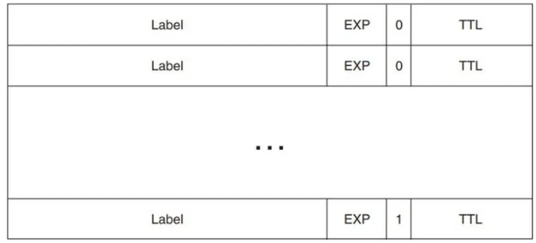
The MPLS header is a 4-byte header composed of four fields, the Label, EXP, BoS and the TTL as the figure below shows:
Figure 1.7: MPLS Header
• Label: 20 bits in length hold the label integer value.
• Experimental (EXP): 3 bits field used for QoS marking.
• Bottom of Stack (S): a one-bit flag, when set to 1, it means that the header directly precedes the IP header while the rest are set to zero.
• Time to Live (TTL): 8 bits in length, serves as the number of hops left for the packet before it is discarded by the router, with a maximum of 256 hops.
When an unlabeled packet enters an MPLS network, the LSR pushes a label and copies the IP TTL to the MPLS TTL field, then it will be decreased as it goes through the MPLS network while the IP TTL will stay intact, once the last label is popped the egress LSR copies the MPLS TTL value to the IP TTL field.
1.6.1 Label stacking
MPLS applications need several labels on each packet, this is done by stacking MPLS headers on top of each other, where all the headers have a Bottom of Stack equal to zero except the bottom label that precedes the IP header directly.
17
Figure 1.8: Label stack
1.6.2 MPLS Encapsulation
MPLS forwards traffic based on labels without performing any IP lookup thanks to its header placement, right after the layer 2 protocol header (Ethernet, PPP or HDLC) and right before the transported network protocol, some say MPLS header operates at layer 2.5, the following figure shows where it is placed:
Figure 1.9: MPLS Header Placement
1.7 Conclusion
In this chapter, we have seen how label forwarding functions and how LDP and all the information base structures contribute to it, the MPLS encapsulation and how MPLS logic could be used to introduce several applications for different purposes.
18
Chapter 2
MPLS VPN
In this part of thesis, we will get to discover one of MPLS major applications, MPLS VPN; we will have a brief walkthrough in its history followed by a deeper discussion of its main operations.
19
2.1 Introduction
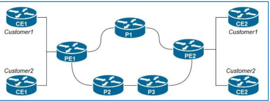
As seen in the previous section, MPLS unicast IP forwarding doesn’t have that much added value on its own with today’s technology and CEF implementation, however, its applications are what makes it so powerful, and one of the most popular applications is the MPLS VPN, which allows service providers to provide some important services such as Layer-3 VPNs that allow WAN connectivity between customers’ remote sites, replacing the traditional Layer-2 WAN services and providing the customers with the same privacy they had with WAN services while ensuring that the overlapping prefixes of the private addresses in each site do not cause any problems. MPLS VPN uses the MPLS unicast IP forwarding inside the SP MPLS network, with some added features on the edge LSRs, alongside Multi-Protocol BGP (MPBGP) to handle the huge number of customers’ internetworks. The following figure shows the typical MPLS VPN architecture connecting four remote sites that belong to two different customers.
Figure 2.1: MPLS VPN Architecture We can distinguish three types of LSRs, as follows:
• Customer Edge Router (CE): it has no MPLS awareness and it is directly connected to the PE Router.
• Provider Edge Router (PE): shares at least one link with a CE, contains the customer-tailored VRFs and has multiple control plane protocols enabled.
• Provider Router (P) found in the SP MPLS network, forwards labeled traffic only, between the PEs.
20
2.2 Control Plane
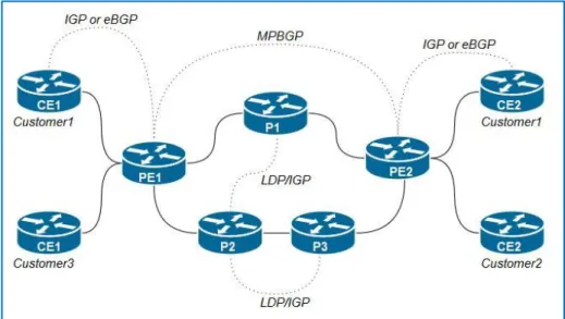
In order to see the bigger picture of the MPLS VPN, we can focus on the control plane protocols included, P and PE routers run LDP alongside one of the IGPs in order to map the whole MPLS network and execute MPLS unicast IP forwarding, meaning the P and PE can forward packets from the ingress PE to the egress PE to provide the WAN connectivity.
PEs has a range of other tasks, which are oriented towards learning customer routes and tracking of which routes belong to which customers.
PEs has a range of other tasks, which are oriented towards learning customer routes and tracking of which routes belong to which customers. PEs exchange routes with the connected customer edge (CE) routers from various customers, using either eBGP, RIPv2, OSPF, or EIGRP, noting which routes are learned from which customers to keep track of the possibly overlapping prefixes, PE routers do not put the routes in the normal IP routing table—instead, PEs store those routes in separate per-customer routing tables, called VRFs. Then the PEs use Multi-Protocol BGP to exchange these customer routes with other PEs never advertising the routes to the P routers, the figure below shows these control plane concepts [1]:
21
2.3 MPBGP Instances
MPBGP plays a crucial role in MPLS VPN control plane by advertising customers’ routes while keeping them separate between PE routers, to achieve this, three important instances has been introduced:
• Virtual Routing Forwarding ( VRFs ).
• Route Distinguishers ( RDs ).
• Route Targets ( RTs ).
2.3.1 Virtual Routing Forwarding ( VRF )
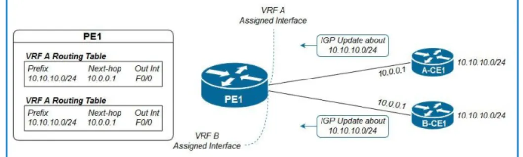
In order to support multiple customers with overlapping addresses schemes, we resort to VRFs, VRFs are basically virtual routers existing in MPLS aware routers only, while typically enabled on PE routers, allowing us to store routes separately for each customer and consequently preventing interferences between customers’ overlapping addresses [1]. Typically, a router needs a VRF for each customer connected to the PE in question, could be used to separate traffic between sites of the same customer, where we can use different VRFs for the same customer [4]. The following figure puts the VRF concept more in-depth:
Figure 2.3: VRF Process We can break this process to these two steps:
1. A-CE1 and B-CE1 send IGP updates to PE1 about the 10.10.10.0/24 subnet.
22
2. PE1 receives an IGP update about 10.10.10.0/24 on its VRF-A assigned interface, so it places it in the VRF-A routing table.
3. PE1 receives an IGP update about 10.10.10.0/24 on its VRF-B assigned interface, so it places it on the VRF-B routing table.
VRFs, being virtual routers, have these major instances as well:
• Routing Information Base ( RIB ).
• Forwarding Information Base ( FIB ).
• A separate instance or process of the IGP used to exchange routes with the CEs.
2.3.2 Route Distinguisher (RD)
While VRFs are used to separately store routes on PEs, they cannot be used to advertise the routes between the customers sites separately, that is why there was an added "number" before the network layer reachability information (NLRI) prefix in the BGP update, that was destined to make each route unique to a customer by assigning a unique number for each customer, all thanks to the MPBGP RFC 4760 that allows the redefinition of an additional number, conventionally called an Address Family to be added before the NLRI prefix, in order to support the MPLS VPN, namely, the Route Distinguisher (RD) [8].
Network Layer Reachability Information (NLRI) is exchanged among BGP routers using UPDATE messages. An NLRI is composed of a LENGTH and a PREFIX. The length is a network mask in CIDR notation (e.g. /25) specifying the number of network bits, and the prefix is the Network address for that subnet [1].
Route distinguishers, which are an MPBGP address family (VPNv4), are used to distinguish between duplicate addresses while advertising for them with MPBGP by adding them before the prefix in the NLRI which will make them unique, since every customer has his own RD, as a result the NLRI will become a 96 bits address composed of:
23
• A 32-bit IPv4 Address
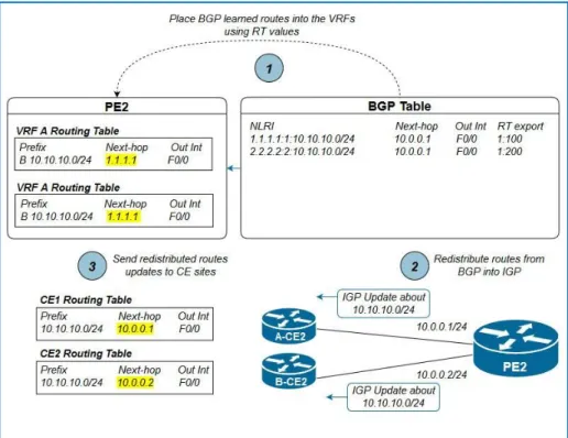
Figure 2.4: IGP to BGP VPNv4 Routes Exportation
What happens is that the PE router redistributes the routes found in the VRFs learned by OSPF into BGP, resulting in extracting an RD from each VRF, and store them in its BGP table so it can advertise them to the other Pes, and since the BGP table has all redistributed routes, the appended RD value will make storing duplicate addresses possible.
RD formatting
RD is eight bytes long, while the first two bytes are reserved for the type, we can configure the rest of the six bytes under three formats:
• 4 bytes integer:2 bytes integer.
• 2 bytes integer:4 bytes integer.
• 4 bytes in DDN: 2 bytes integer.
We must note that the first half of the RD has to be either an ASN number or an IPv4 address.
2.3.3 Route Target (RT)
We have seen how MPLS VPN solved the duplicate addressing scheme, through RDs and VRFs respectively, the only remaining problem, is how do egress PEs know in which VRFs should they place the advertisements?
Route Targets (RT), MPLS uses RTs to determine in which VRF the advertisements should be placed, RTs are also a redefinition of a BGP advertisement update field, called the extended
24
community, an 8-byte field, while advertisements are bound to only one RD, they can be marked by several RT values, we can discern two types of RTs [1]:
• Export RT: Configured on the ingress PE.
• Import RT: Configured on the egress PE.
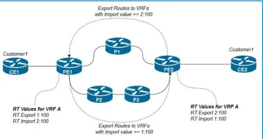
When the advertisement arrives, the egress PE runs the export RTs against its import RTs and places the information into the respective VRF when a match occurs, as the following figure shows:
Figure 2.5: Routes Exportation and Importation
It is important to note that this process is unidirectional, if the egress PE in this case, advertises routes from the CEs connected to it, it should have its own Export RT and the ingress PE should have its own Import RT.
2.4 PE-CE Routing
After seeing the bigger picture of how MPLS VPN functions from a control plane standpoint, we need to break its process into two important parts, the PE-CE routing and the PE-PE routing.
25
2.4.1 Ingress PE-CE Routing
First, we will discuss the ingress PE-CE routing, we need to implement an IGP or even an eBGP instance between the CE and the ingress PE routers VRF in order to advertise routes in the CE site to the PE, more specifically the PE VRF routing table, that is reserved for that customer [8].
Figure 2.6: Ingress PE-CE Routing Process Overview
As this figure 2.6 shows, We can see that A-CE1 and B-CE1 are connected to PE11 via the interfaces assigned to VRF-A and VRF-B (F0/0 and F0/1 respectively), now we need to run two different IGP instances on PE1 to form an adjacency with each site, in order to advertise routes on the sites, as a result, we can see that each VRF routing table has an entry for 10.10.10.0/24 with A-CE1 and B-CE1 as next-hops learned by the said IGP.
2.4.2 Egress PE-CE Routing
Now, we will see the egress PE-CE routing. After forwarding the MPBGP updates between the PE routers, the routes are placed into the BGP table as VPNv4 routes, then the egress PE router will add the VPN label to its LFIB, then strip the RD and RT values and place the routes as IPv4 routes in the appropriate VRFs, as BGP-learned routes with the ingress PE loopback address as next-hop, afterwards, the egress PE will perform route redistribution on the learned routes, from BGP to the IGP used on the VRF and then advertise them to the CE sites, which will receive these routes as IGP-learned routes with the egress PE2 VRF assigned interface as next-hop, the following figure sums up the whole process.
26
Figure 2.7: Egress PE-CE Process Overview
2.5 PE-PE Routing
After injecting the IGP-learned IPv4 routes in the PE router VRFs as shown in figure 2.6, we need to forward them to the other PE routers in the MPLS network. MPBGP supports several address families alongside IPv4 such as VPNv4, which are IPv4 routes prepended with RDs and appended with RTs, alongside a VPN label and hence the Multi-Protocol BGP naming, commonly, MPLS VPN designs use a loopback as update source on the PE routers, the following scheme demonstrates the process [8].
Figure 2.8: PE-PE Operations Steps
27
2. PE1 place them in the appropriate VRF depending on the incoming interface.
3. PE1 performs route redistribution from IGP IPv4 routes to BGP VPNv4 routes.
4. PE1 sends them to the egress PE by LDP-learned label switching.
5. The egress PE will place the BGP-learned routes in the appropriate VRFs based on RT values.
6. The egress PE will now perform a route redistribution to the IGP and then advertise the redistributed routes on the CE site.
2.6 Data plane
Data plane wise, MPLS VPN is different from the MPLS Unicast IP forwarding, where the Ingress PEs need to impose not one but two labels in order to forwards the traffic to the Egress PE while keeping the customers’ traffic separate as
follows:
• An outer label with the Bottom-of-Stack set to 0, with a label that allow it to be forwarded to the Egress PE, based on the global CEF FIB and advertised via LDP.
• An inner label with the Bottom-of-Stack set to 1, with a label that defines the VRF this traffic belongs to, signaled by the MPBGP; it also goes by the name of VPN label or BGP label.
28
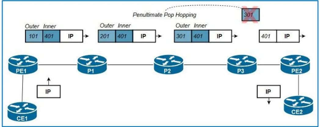
Figure 2.9: MPLS VPN Traffic Forwarding Paradigm
Penultimate Pop Hopping
As seen previously, the MPLS VPN data plane needs two labels in order to function, however, this way, the egress PE would receive two labels stacked and thus do two LFIB lookups just to find out it needs to pop both of these labels and perform an IP lookup in the CEF FIB, which is considered inefficient and unnecessary, so to avoid this and make things more efficient, the Penultimate Pop Hopping (PHP) was introduced, where the second-to-last (penultimate) P router pops the outer label (Global LFIB label) and leaves the VPN label ( VRF LFIB label) to be popped by the egress PE router before forwarding the traffic, for this to happen the egress router must advertise label 3 (label 3 is the implicit null label) to the penultimate router via LDP.
29
2.7 Overlapping VPN
MPBGP supports multiple extended communities and therefore multiple Route Distinguishers, and this has been in what is called overlapping VPN, it occurs when routes advertisements are meant for different VPNs in the MPLS Cloud. There are many variations to overlapping VPN, the most common is having one site reachable by some of the customers in the same MPLS cloud.
This technology allows us to send VPNv4 route updates to several customers by including a second export RT that matches the customer whom we’d like to have connectivity with, import RT, alongside the primary RT that matches our import RT, the following figure demonstrates how Overlapping VPN can be used:
Figure 2.11: Overlapping VPN Design Example
In this example, Customer 1 sites have full connectivity with each other, same goes for Customer 2 sites, however sites Customer1-CE1 and Customer2-CE2 have connectivity with the Centralized Servers connected to PE3 as well, we need to follow these steps to implement this design:
1. Create a VRF for Serv site on PE3.
2. Configure two export RT values for that VRF that match the import RT values of CE1 on PE1 and CE2 on PE2.
30
We do not need to configure any import RT values for VRF-Serv, as this design doesn’t require the centralized servers to have connectivity to the customers’
sites.
Layer2 VPN
The existing MPLS network offers multiple types of VPNs namely Layer2 and Layer3 VPNs, in a layer2 VPN, L2 frames (Could be Ethernet, ATM, Frame Relay or PPP/HDLC) are transported between locations. In the more general case, it’s similar to a virtual cable connecting two switches in separate buildings. The VPN has to handle all basic properties of layer 2, taking Ethernet for example: learning MAC addresses (ARP Protocol), replicating broadcast and multicast frames, etc. This can be easily done by tunneling frames over the VPN. Tunneled L2 VPNs are conceptually simpler than L3 VPNs, and if properly implemented, can be completely transparent to applications. On the other hand, it potentially suffers from all problems that plague standard L2 extensions, including security issues and L2 instabilities [1].
In a layer 3 VPN, as previously demonstrated, each side of the connection is on a different subnet, and IP packets are routed through the VPN. The design is potentially more scalable than a L2 VPN, and offers more security than a simple L2 implementation, However, for a host of unrelated reasons L3 VPNs rarely offer the same level of transparency offered by L2 VPNs, and may interfere with applications [10].
2.8 Conclusion
The most popular MPLS-enabled application in operations is MPLS VPN network. This chapter discuss the different operation of MPLS VPN both in control plane in forwarding plan,explain different protocols applied and the label forwarding mechanism.
31
Chapter 3
MPLS Traffic Engineering
In this chapter, we will see how MPLS TE works. We will get to know how Open Shortest Path First (OSPF) was extended so that it can advertise traffic engineering (TE) information, and that the signaling protocol Resource Reservation Protocol (RSVP) was also extended to suit TE needs. We will discover how the LSR calculates the paths of TE tunnel label switched paths (LSP), how it signals them, and how it calculates their cost. We will also take a look on how to forward traffic into TE tunnels. Finally, we will see how MPLS TE can be tweaked to be used in MPLS VPN.
32
3.1 Introduction
Traffic engineering TE is a feature that has for a goal to get traffic between two points in the most optimal way, it was first implemented in ATM/Frame relay networks, however, since these technologies started deprecating and IP networks started dominating, it was necessary to implement it, while it is not possible in a pure IP network, it was implemented in an IP/MPLS Network.
IP Routing has one important principle which is to get traffic to the destination in the most efficient way, time-wise, that is why all the metrics of the IGPs are influenced by this principle, which try to choose the most optimal route based on the link cost, bandwidth or number of hops, however, IGPs do not take bandwidth amongst other link attributes such as delay and jitter into account, which might lead to link overutilization and thus data loss, while leaving other links underutilized, we can solve this problem by influencing the traffic flow through the MPLS network depending on the traffic needs and importance to highly optimize our network infrastructure usage, saving us a great deal of planning and cost. TE can dynamically adapt when dealing with unexpected network node failures, where we can prioritize traffic flows according to their importance and in order to preserver the customers SLA agreements
3.2 TE Link Attributes
Every link in the MPLS-enabled network has characteristics that are pertinent to TE, these attributes are flooded between MPLS-TE routers in order to create a TE Database (TED) that is later used to conceive an MPLS-TE Topology that has the best paths for each tunnel to use, for now we will see the following attributes:
Max reservable bandwidth:
As its name indicates, this represent how much of the link bandwidth can be reserved for TE Tunnels.
Attribute Flags:
These are 32-bit flags that have no syntax, operators to indicate 32 different link capabilities and properties for instance use them, and we can indicate that a link has low-latency by configuring its attribute flag to 0 x 4.
33
In order for the TE Tunnel to take these flags into consideration we must configure the affinity bits and mask on it, which are also 32 bits long. Both the Attribute flags and the Tunnel Affinity bits will be masked according to the Affinity mask and then the unmasked part must be identical in order for the Tunnel to accept this path as a potential path otherwise it the path crossing this node will be dropped.
This could be used for instance to prevent bulk data traffic tunnels from using VoIP links by playing on the affinities of both tunnels.
TE Metric:
Metric are used by IGP protocols in order to pick the best route amongst all the routes provided by one IGP, and since MPLS TE needs a metric to choose the best available path, so by default they use the IGP metric, however there’s the TE metric that also could be used as the primary metric for MPLS-TE, note that TE metrics are by default equal to IGP metrics.
This duality can be useful, in case we want to influence the path taken by the TE Tunnel, because instead of influencing the IGP link metric, which would influence IP traffic as well, we can instruct the TE Tunnel to use TE link metric and change it accordingly, this way we’ll have two different topologies, one for IP and the other for MPLS TE, this feature is called Dual TE Metrics [2].
3.3 TE Information distribution
In the previous section, we have seen some of the MPLS-TE relevant link attributes, in this section we will see how these characteristics are flooded in the MPLS-TE network.
Unlike Distance vector protocols that only advertise their best routes to their peers, Link-state protocols do advertise a full update about all their links, this way, every router has a complete idea about the topology. In order for the head router (the router that will create the TE-Tunnel) to choose the best path for its Tunnel, it needs to have all the relevant topology information, which are the aforementioned link attributes mostly, and that explains why we use Link State IGPs in MPLS networks when deploying Traffic engineering, the next title will explain how OSPF is used to populate the TE Database [2].
34
3.4 OSPF-TE Adaptation
In order to adapt the OSPF protocol to Traffic, there has been added three LSAs following the RFC 2370, LSA 9,10 and 11, having different flooding scopes, we’ll be using the LSA 10 since it has the perfect flooding scope for us, which is areawide while the LSA 9 an 11 have a link-local scope and an AS scope respectively, these aforementioned LSAs are called Opaque LSAs, in order for routers to recognize routers that can support opaque LSAs, an O-bit was introduced into the OSPF options field, this field exists in:
• Hello Messages.
• Database Description.
• All LSAs.
More specifically, OSPF uses TLVs to transport the Link attributes, two TLV types exist: Router TLV, carrying the TE RID and a Link TLVs, that is composed of several sub-TLVs that describe the link characteristics, such as:
• Traffic Engineering Metric (4 bytes).
• Maximum reservable bandwidth (4 bytes).
• Administrative group or Attribute Flags (4 bytes)[2].
OSPF-TE Advertisements TLV (type-length-value or tag-length-value) is an encoding scheme used for optional information element in a certain protocol. The type and length are fixed in size (typically 1-4 bytes), and the value field is variable.
3.4.1 OSPF-TE Advertisements
Same as IP IGP advertisement, TE-IGP advertisements are triggered by certain events which are:
• Link status change :
The link status (up or down) means either that new paths are available that could be the most optimal or that a path in use has failed and thus new calculations are needed.
35
• Manual Configuration Change
• Periodic flooding:
Manual Configuration Change all IGPs have a timer for their periodic flooding, that is usually relatively long, the default periodic flooding timer for OSPF is 30 minutes however opaque LSAs (TE Information) are flooded every three minutes.
• Changes in bandwidth ( reserved/unreserved ):
Small changes in the available bandwidth do not necessarily trigger an opaque LSAs flooding, however, when the changes are relatively important, TE information is flooded, by default there are several triggering milestones for both ways, meaning for when the available bandwidth is being freed or being reserved, the concept is detailed in the following figure.
Figure 3.1: IGP-TE Update Triggers Thresholds
• Tunnel Setup Failure:The head end router doesn’t request for a path for its Tunnel unless it has done all the needed calculations that prove that a certain path is capable of holding the tunnel, a setup failure means one of the IGP-provided information has changed and the setup cannot be done, this require the updated TE information and hence flooding must happen [2].
36
3.5 MPLS-TE Tunnels (Attributes and Path calculation PCALC)
We have seen in the previous sections the necessary TE information that the head end router needs and how it is forwarded throughout the MPLS network; in this section, we will discuss the Tunnel attributes and other relevant operations. MPLS TE Tunnel has several characteristics; we will see the following in detail:Affinity bits and mask
As mentioned in the Link attributes section, these are 32-bit succession that is masked by the affinity mask. As the Figure 0x0 shows, in order for the Tunnel to choose a certain path, each link masked Attribute flags must conform to the masked bits of the Affinity bits.
Tunnel destination
This is the destination (or the tail end) router TE Router ID, where the tunnel traffic should be forwarded.
Desired bandwidth
This attribute specifies the least bandwidth that the Tunnel path should have on every link from the head end router to the tail end router.
Tunnel Priorities
One of the advantages of using Traffic Engineering is the adaptation to network changes be it node failures or a new configuration, where you can set certain priorities to each tunnel and thus prioritize traffic on your network when needed, for this, we use two priorities: Setup and Hold priorities, to define which tunnel should take the link reservation when of course, we’re short on link resources, such as bandwidth, they’re ranged from 0 to 7, the lower the priority the more important the link is, if Tunnel 1 setup priority is lower than Tunnel 2 hold priority hold, it means that Tunnel 1 is more important than Tunnel 2 and it can preempt it and take over the link reservation, that is why we should not set a hold priority that is lower than the setup priority, because then, the tunnel would preempt another tunnel because of its low Setup priority but then get preempted once it is setup, because of its hold priority.
37
Path options
Once you configure a TE Tunnel, it needs a TE LSP that meets all its preconfigured requirements to route traffic through the network to the tail end router, these TE LSPs are called paths and we have two types:
1. Explicit Paths: these are the paths that you configure manually, by specifying each node that the Tunnel needs to go through until the tail end, but this is mostly administratively challenging in relatively big MPLS networks.
2. Dynamic Paths:, however, Dynamic paths are calculated by the head end router by running the path calculation algorithm (PCALC or CSPF) against the TE Database (TED), populated by the link state IGP, taking into account all the Tunnel requirements and the link attributes pertinent information the head end router only needs the tail end router address.
There can be multiple dynamic and explicit paths for a single Tunnel to try and use, each path has a preference value (the lower the better) the tunnel will signal the most preferred path by sending RSVP messages (Will be discussed in detail in the next section), if the tunnel happens to not find any working path, it turns to a down interface status.
Re-optimization
As we mentioned before, MPLS Traffic engineering has for a goal to forward traffic between two edges in the most optimal way, which is covered prior to the Tunnel setup by Setup and Hold priorities, however, MPLS TE needs to adapt if a new optimal paths are available after the setup, for that there has been introduced 3 triggers to help reoptimize the Tunnels paths:
1. Periodic Re-optimization: There is a timer that is set to one hour by de-fault.
2. Event-driven Re-optimization: We could instruct head end routers to perform re-optimization once a link is operational and on standby for TE operations, this is isn’t functioning by default.
3. Manual Re-optimization: You can instruct the head end router to perform a re-optimization globally or per-tunnel through the CLI [2].
38
3.6 RSVP Tunnel Establishment (RSVP)
Up until now, we have seen how the head end router finds the most optimal paths for its configured Tunnels after using the information in the TED gathered by the LS IGPs, now we will see how these Tunnels are established to be ready to
forward traffic.
MPLS TE uses Resource Reservation Protocol (RSVP) in order to signal the Tunnel chosen path on each interface in the calculated path and consequently to reserve the link a resource for the said tunnel, for this RSVP uses two messages: PATH and RESV, it operates this way:
1. The head end router sends a PATH message that has a list of IP addresses of the calculated path stored in the Explicit Route Object (ERO) to the first hop of the path.
2. Each LSR in the path receiving the PATH message, removes its address from the ERO and forwards it to the next hop, until it reaches the tail end router.
3. Tail end router returns a RESV message in the exact path to the head end router
4. Once the head end router receives the RESV message error-free, the tunnel has all the link resources reserved and it becomes operational.
RSVP is also responsible of defining the path as an LSP path, making the tunnel have its own labels, for this, the RESV message has a label field, where each router receiving a RESV, places the label in the received message as an outgoing label for that tunnel in its CEF LFIB and then places its local Tunnel label in the RESV to be forwarded to the next hop on the way from the tail end to the router end, note that the tail end sends an explicit null in the label field of the forwarded RESV message, in order for the Penultimate-Pop-Hopping to occur, Fig 0xF sums up the RSVP signaling operation:
39
Figure 3.2: RSVP-TE Operations
This means that the RSVP is responsible for the label distribution meaning that LDP is not mandatory for the MPLS TE to operate, we must note that Tunnel paths are unidirectional [2].
3.6.1 Enabling TE Tunnels
After making the tunnel operational, we need to instruct traffic flow to take the tunnel LSP path. There are different ways to accomplish that; these are some of the methods:
1. Static routing : This is done through configuring a static route to a destination with the tunnel interface as the outgoing interface.
2. Policy-based Routing : PBR allow us to direct traffic in a more granular way, based on the source, the protocol used or the kind of traffic, to a specific interface, by creating a policy and map it to the incoming interfaces.
3. Forward Adjacency : This feature makes it possible to advertise for tunnels in the IGP advertisements making it look as if the tunnels were direct links between the head end router and the tail end router, However, we must configure a second tunnel for each existing tunnel that is being advertised, because Tunnels are unidirectional where IGP routes are two-way routes[2].
40
3.7 MPLS VPN Adaptation
Forwarding from CE to CE works with all VPNv4 traffic carried over the TE tunnels. If the BGP next hop is not the same as the TE tunnel destination, LDP must be run in the core and on the TE tunnel.
This section details how MPLS VPN and TE can coexist in one network, allowing MPLS VPN to benefit from TE advantages, however, this coexistence requires some tweaking to avoid packet forwarding possible failures.
We can distinguish two scenarios for this implementation, setting up a tunnel between the ingress and egress PE routers, or between LSRs in the MPLS network.
3.7.1 PE-PE Routers Tunnel
We can instruct VRF traffic to flow over a TE Tunnel linking both PE routers, or more correctly, a dual-tunnel linking them back and forth, in this scenario, the LSRs do not need LDP to distribute labels because that is taken care of by RSVP RESV messages as seen previously, the traffic will have two distinct labels stacked, the outer label will be the Tunnel label while the inner label will carry the VPN label.
Figure 3.3: PE1-PE2 Tunnel Path
In order to instruct the VPN traffic to choose the Tunnel over the traditional LSP, we must point the tunnel as the next hop for the BGP VPNv4 route instead of the egress PE loopback address conventionally used [2].
41
3.7.2 PE (or P)-P Tunnel
This following scenario requires tweaking and adaptation as it cannot function properly on its own.
Figure 3.4: P1-P3 Tunnel Path
This way, the traffic will leave the P1 router having two labels, one for TE and one for VPN, however, with the P tail end router sending an implicit null in the RESV message to the upstream router (P2 in this case) for the PHP to occur, P2 router will receive a packet with only a VPN label on it, on which it’ll take action by either dropping the packet because there is no match in the LFIB table or by forwarding it to the wrong destination in case a match for that VPN label in its LFIB, and consequently never reach the egress PE router, since VPN labels are only meant to be used by the PE egress routers.
In order to solve this problem, we need to follow these two steps:
1. Enable LDP on all links, in order to forward labeled traffic to the head-end router and from the tail-end router to the egress PE router.
2. Configure a targeted LDP session between the head-end and tail-end routers, as a result, the tail-end router, will advertise its labels to the head-end router, consequently, the head-end will have an LFIB entry for the egress PE router, so it will have not two but three labels:
a. TE Label (Top label): contains the labels of the tunnel path LSP towards the tail-end.
b. LDP label (Second label): will contain the advertised labels to reach the egress PE router.
42
Figure 3.5: P-P Tunnel Data plane Overview [2]
3.8 Conclusion
In this chapter, we explained the need for Traffic Engineering in networking, we walked through the link attributes related to TE and how OSPF was tailored to disribute these information to the head-end router, how these information are used to calculate and establish a TE tunnel.
43
Chapter 4
MPLS Quality of Service
In this chapter, we will see different QoS models, we will learn about QoS tools, how to protect voice, video and data traffic using various QoS mechanisms, we will be Describing the various classification options for distinguishing one packet from another, also the various marking options, we will Discusses the various tools that can be used to meter and regulate packet flows, including policies, shapers and markers, we will discuss about Congestion Management and Avoidance Tools, finally we will see different kind off DiffServ tunneling models and how to implement them on the MPLS network .
4.1 Introduction
Quality of service (QoS) has become popular the past few years. Few networks have unlimited bandwidth, so congestion is always a possibility in the network. QoS is a means to prioritize important traffic over less important traffic and make sure it is delivered; there are four characteristics of network traffic that we must deal with:
Bandwidth is the speed of the link, so each traffic has one queue we can configure the router so the queue can get a percentage of the bandwidth. Delay is the time it takes for a packet to get from the source to a destination, this is called the one-way delay. The time it takes to get from a source to the destination and back is called the round-trip delay. Jitter is the variation of one-way delay in a stream of packets. Loss is the amount of lost data, usually shown as a percentage of lost packets sent.
44
4.2 End to End Qos Models
End-to-end QoS is the ability of the network to deliver service required by specific network traffic from one end of the network to another, there are three types of service models: best effort, integrated, and differentiated services.
Best-Effort Service
Best effort is a single service model in which an application sends data whenever it must, in any quantity, and without requesting permission or first informing the network. For best-effort service, the network delivers data if it can, without any assurance of reliability, delay bounds, or throughput. Best-effort service is implemented by FIFO
Integrated Service
In this model the application requests a specific kind of service from the network before it sends data. So we use the signaling protocol Resource Reservation Protocol (RSVP). The hosts signal to the network via RSVP what the QoS needs are for the flows of traffic that they send.
Differentiated Service
The DiffServ bits in the IP header to qualify the IP packet to be of a certain QoS. The routers look at these bits to mark, queue, shape, and set the drop precedence of the packet. The big advantage of DiffServ over IntServ is that the DiffServ model needs no signaling protocol.
4.3 Quality of Service Tools
4.3.1 Classification and Marking
Classification: an action that sort packets into different traffic types, to which different policies can then be applied. Classification of packets can happen without marking. Marking: Writes a value into the packet header. It is usually establishes a trust boundary at the network edge or at the intersection between two different networks, where preexisting packet markings are accepted or rejected (and as such, re-marked). Marking also can be used in other locations in the network and is not always used solely for purposes of classification [6].
45
IP Precedence: Differentiated QoS
DiffServ with IP Packets: IP precedence utilizes the 3 precedence bits in the IPv4 header’s Type
of Service (ToS) field to specify class of service for each packet, as shown in Figure 4.1:
Figure 4.1: IP Precedence ToS in an IP Packet Header
The usage of the precedence bits for QoS is now widely used throughout the world for many networks. The drawback of the precedence bits, however, is that only three exist, which means there are eight levels of service. Therefore, the IETF decided to dedicate more bits for QoS. The four TOS bits were deprecated, and three of them were assigned to DiffServ QoS, in addition to the three precedence bits. DiffServ ended up with six bits, providing more than enough levels of QoS [5].
Figure 4.2: DiffServ with IP packets
DiffServ with MPLS Packets : There are three EXP we can use these bits in the same way that we use the three precedence bits in the IP header, so the label switched path is changed to an E-LSP
46
indicating that the label switching router will use the EXP bits to schedule the packet and decide on the drop precedence .
Figure 4.3: DiffServ with MPLS Packets PBR: Policy-Based Routing
Policy-Based Routing (PBR) allows to classify traffic based on extended access list criteria, set IP precedence bits, and even route to specific traffic engineered paths that may be required to allow a specific QoS through the network. By setting precedence levels on incoming traffic and using them in combination with the queuing tools, you can create differentiated service. These tools provide powerful, simple, and flexible options for implementing QoS policies in your network [9].
Using policy-based routing, route maps are made to match on certain flow criteria and then set precedence bits when ACLs are matched. The capability to set IP precedence bits should not be confused with PBR’s primary capability: routing packets based on configured policies. Some applications or traffic can benefit from QoS-specific routing-transferring stock records to a corporate office (for example, on a high-bandwidth, high-cost link for a short time), while transmitting routine application data such as e-mail over a lower-bandwidth, lower-cost link. PBR can be used to direct packets to take different paths than the path derived from the routing protocols. It provides a more flexible mechanism for routing packets, complementing the existing mechanisms provided by routing protocols.
Also available using route maps is the capability to identify packets based on Border Gateway Protocol (BGP) attributes such as community lists and AS paths. This is known as QoS policy propagation via Border Gateway Protocol[3].
CAR: committed access rate
Similar in some ways to PBR, the CAR feature allows to classify traffic on an incoming interface, it also allows specification of policies for handling traffic that exceeds a certain
47
bandwidth allocation. CAR looks at traffic received on an interface, or a subset of that traffic selected by access list criteria, compares its rate to that of a configured token bucket, and then takes action based on the result (for example, drop or rewrite IP precedence) [9].
CAR is used to police traffic flows to a committed access rate. CAR does this with a token bucket. A token bucket is a bucket with tokens in it that represent bytes (1 token = 1 byte). The bucket is filled with tokens at a user-configured rate. As packets arrive to be delivered, the system checks the bucket for tokens. If there are enough tokens in the bucket to match the size of the packet, those tokens are removed and the packet is passed (this packet conforms). If there aren’t enough tokens, the packet is dropped (this packet exceeds) [6].
NBAR: Dynamic Identification of Flows
Cisco’s newest method of classification is Network Based Application Recognition (NBAR). This method is used to identify the traffic it can identify various applications that use ephemeral ports .NBAR does this by looking at control packets to determine which ports the application decides to pass data on. NBAR adds a couple of interesting features that make it extremely valuable. One feature is a protocol discovery capability. This allows NBAR to baseline the protocols on an interface. NBAR lists the protocols that it can identify and provides statistics on each one. Another feature is the Packet Description Language Module (PDLM), which allows additional protocols to be easily added to NBAR’s list of identifiable protocols. These modules are created and loaded into Flash memory, which then is uploaded into RAM. Using PDLMs, additional protocols can be added to the list without upgrading the IOS level or rebooting the router.
4.3.2 Congestion-Management
FIFO: First in, First out
FIFO is an acronym for First In First Out. This expression describes the principle of a queue or first-come-first-serve behavior: what comes in first is handled first, what comes in next waits until the first is finished etc. Simply, FIFO queuing involves storing packets when the network is congested and forwarding them in order of arrival when the network is no longer congested. FIFO is the default queuing algorithm in some instances, thus requiring no configuration, but it