HAL Id: hal-01736050
https://hal.archives-ouvertes.fr/hal-01736050
Submitted on 23 Mar 2018
HAL is a multi-disciplinary open access
archive for the deposit and dissemination of
sci-entific research documents, whether they are
pub-lished or not. The documents may come from
teaching and research institutions in France or
abroad, or from public or private research centers.
L’archive ouverte pluridisciplinaire HAL, est
destinée au dépôt et à la diffusion de documents
scientifiques de niveau recherche, publiés ou non,
émanant des établissements d’enseignement et de
recherche français ou étrangers, des laboratoires
publics ou privés.
Controlled drive-in and precipitation of hydrogen during
plasma hydrogenation of silicon using a thin
compressively strained SiGe layer
F. Okba, Nikolay Cherkashin, Z. Di, M. Nastasi, F. Rossi, A. Merabet, Alain
Claverie
To cite this version:
F. Okba, Nikolay Cherkashin, Z. Di, M. Nastasi, F. Rossi, et al.. Controlled drive-in and
pre-cipitation of hydrogen during plasma hydrogenation of silicon using a thin compressively strained
SiGe layer. Applied Physics Letters, American Institute of Physics, 2010, 97 (3), pp.31917-31917.
�10.1063/1.3467455�. �hal-01736050�
Controlled drive-in and precipitation of hydrogen during plasma hydrogenation of
silicon using a thin compressively strained SiGe layer
F. Okba, N. Cherkashin, Z. Di, M. Nastasi, F. Rossi, A. Merabet, and A. Claverie
Citation: Appl. Phys. Lett. 97, 031917 (2010); doi: 10.1063/1.3467455 View online: https://doi.org/10.1063/1.3467455
View Table of Contents: http://aip.scitation.org/toc/apl/97/3
Published by the American Institute of Physics
Articles you may be interested in
Temperature dependencies of hydrogen-induced blistering of thin film multilayers
Journal of Applied Physics 115, 173510 (2014); 10.1063/1.4875484
Plasma hydrogenation of strained heterostructure for layer transfer without ion implantation
Controlled drive-in and precipitation of hydrogen during plasma
hydrogenation of silicon using a thin compressively strained SiGe layer
F. Okba,1,2N. Cherkashin,1,a兲Z. Di,3M. Nastasi,3F. Rossi,4A. Merabet,2and A. Claverie1
1
CEMES/CNRS and University of Toulouse, Groupe nMat, 29 rue J. Marvig, 31055 Toulouse, France 2
Département Optique et Mécanique de Précision, Faculté des Sciences de l’Ingénieur, Université Ferhat Abbas, Sétif 19000, Algeria
3
Materials Physics and Applications Division, Los Alamos National Laboratory, Los Alamos, New Mexico 87545, USA
4
Joint Research Centre, European Commission, Ispra(Va) 21020, Italy
共Received 26 May 2010; accepted 1 July 2010; published online 23 July 2010兲
We have quantitatively studied by transmission electron microscopy the growth kinetics of platelets formed during the continuous hydrogenation of a Si substrate/SiGe/Si heterostructure. We have evidenced and explained the massive transfer of hydrogen from a population of platelets initially generated in the upper Si layer by plasma hydrogenation towards a population of larger platelets located in the SiGe layer. We demonstrate that this type of process can be used not only to precisely localize the micro-cracks, then the fracture line at a given depth but also to “clean” the top layer from pre-existing defects. © 2010 American Institute of Physics.关doi:10.1063/1.3467455兴
In the conventional ion-cut technology 共SmartCut™兲, hydrogen ion implantation followed by wafer bonding and thermal annealing is used for the transfer of a Si film onto an oxidized substrate.1This process takes advantage of the pre-cipitation of hydrogen during annealing in the form of quasi-two dimensional defects filled with over-pressurized H2gas.
These defects exert stress in the layer and, during annealing, their thermal evolution from “platelets” of a few tens of nm in diameter to micro-cracks of a few micrometers in diameter and the possibility for them to elastically interact may give rise to the complete exfoliation of the upper layer.2
For high enough implanted fluences, the majority of platelets and subsequent micro-cracks are parallel to a共001兲 Si wafer surface and the thickness of the transferred layer can be monitored by varying the beam energy.1However, the straggling of the implanted ions results in a depth-distribution of platelets and micro-cracks which, in turn, re-sults in a quite severe roughness and relatively high defec-tivity of the transferred layers. For this reason, ultrathin共few nanometer thick兲 layers, desirable for developing advanced silicon-on-insulator technologies, are difficult to fabricate us-ing ion implantation and require time-consumus-ing and costly etching steps.
Plasma hydrogenation, a low cost and flexible technique, can be used to inject hydrogen into silicon.3,4 Nevertheless, as the energy of the H ions impacting the surface is low and spread, the platelets are depth-distributed all over the near-surface region. Moreover, mostly兵111其 platelets not parallel to the wafer surface, the most stable defects in absence of stress,5 are formed during hydrogenation.3–5 As a conse-quence, plasma hydrogenation alone cannot be used to trans-fer layers of sufficiently high crystalline quality.
It has been previously reported that thin SiGe strained layers buried during growth in a Si substrate can be used to favor the formation of platelets parallel to the wafer surface and located on or close to the stressed layer.6,7However, up
to now, the mechanisms responsible for such behavior were not clearly understood and the crystalline quality of the up-per layer was poor due to the formation of platelets and micro-cracks of undesirable orientations therein.
In this work, we identify those mechanisms and demon-strate the possibility to localize all the micro-cracks, and fi-nally the splitting-depth of transferred layers, precisely onto a thin compressively strained SiGe layer while leaving a per-fectly defect-free upper layer by using plasma hydrogena-tion.
For the experiments reported here, a defect-free structure containing a 5 nm thick compressive strained Si0.80Ge0.20 layer covered by a 180 nm thick Si layer was grown by molecular beam epitaxy on a 共001兲 Si substrate. The wafer was cut into four pieces which were subjected to low pres-sure共1 mTorr兲 plasma hydrogenation in pure hydrogen dur-ing 0.5 h, 1 h, 1.5 h, and 2 h, respectively. Hydrogenation was carried out in a distributed electron cyclone resonance plasma reactor with a low frequency 共2 kHz兲 bias equal ⫺100 V.8
The plasma temperature was of about 300 ° C. Specimens were prepared for cross-section共CS兲 imaging us-ing transmission electron microscopy 共TEM兲 along both the 关110兴 and 关010兴 directions by tripod polishing and low energy/current density argon ion-beam thinning until elec-tron transparency. The platelets and micro-cracks seen edge-on contained in a given region of a sample were all detected in TEM images taken under specific out-of-Bragg and out-of-focus conditions.9Then, the thickness of the ana-lyzed areas was estimated by imaging the same zones under well-defined two-beam conditions. The defect populations were statistically analyzed over several images in terms of depth-distributions of their size, concentration, and volume fraction they occupy following the method developed in our previous works.2,9,10
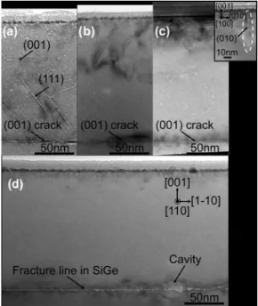
Typical images from the samples subjected to hydroge-nation for 0.5 h, 1 h, 1.5 h, and 2 h are shown in Figs. 1共a兲–1共d兲, respectively. As already reported in Ref. 11, a 10–20 nm thick SiO2 layer is formed on all samples during
hydrogenation. For hydrogenation times up to 1.5 h, different
a兲Electronic mail: [email protected].
APPLIED PHYSICS LETTERS 97, 031917共2010兲
types of platelets lying on兵111其s, 共001兲 and, in much smaller concentrations, on共010兲 planes are observed in the upper Si layer. As the hydrogenation time increases, a defect-free layer appears and develops extending from the SiGe layer towards the surface. After hydrogenation for 2 h, no defects are observed in the Si upper layer关Fig.1共d兲兴 except in a very narrow, a few nanometer thick, layer close to the surface. In all the samples, platelets and/or micro-cracks parallel to the 共001兲 Si surface are observed within the SiGe layer. As the hydrogenation time increases from 0.5 to 1.5 h, the isolated platelets located there grow in size and eventually merge to form cracks. After 2 h of hydrogenation, these micro-cracks have grown in size and/or coalesced and initiate a fracture line in the SiGe layer, thus parallel to the wafer surface. Few round shaped cavities are also observed at the same depth.
Figure2gathered the results of the quantitative analysis of these defect populations in terms of defect density, diam-eter and volume fraction as functions of the depth. After hydrogenation for 0.5 h, the concentration of platelets fol-lows a quasilognormal profile centered at a depth of 60 nm below the surface with a long tail extending toward the SiGe layer 关Fig. 2共a兲兴. As the hydrogenation time increases, this concentration profile shrinks from the long tail side, shifts toward the surface and finally its integral decreases as con-firmed by the evolution of the projected superficial density shown in the inset in Fig. 2共a兲. Interestingly, the concentra-tion of defects within the SiGe layer remains mostly unaf-fected by the hydrogenation time. In all samples, the closer to the SiGe layer the larger the platelets are关Fig.2共b兲兴. The platelets located within the SiGe layer are already larger at the beginning of hydrogenation but further grow faster than elsewhere in the Si layer during hydrogenation关see inset in Fig. 2共b兲兴. As the hydrogenation proceeds, all the platelets grow in size but their growth rate increases when the dis-tance to the SiGe layer decreases. Figure 2共c兲 shows the evolution of the volume fraction occupied by the platelets
and micro-cracks obtained by combining the results shown in Figs.2共a兲and2共b兲. After 0.5 h hydrogenation, the “plate-let phase” mostly occupies a region located in the Si layer from a depth of 80 to 140 nm from the surface. Owing to their very large size there, the platelets occupy a large vol-ume fraction of the SiGe layer. However, when the hydroge-nation proceeds, the volume fraction in the Si layer decreases everywhere but faster close to the surface and to the SiGe layer. In the meantime, it dramatically increases in the SiGe layer. Integrating these depth distributions, we evidence in the inset of Fig.2共c兲 that the volume per surface fraction, V/S, decreases linearly with time in the Si upper layer but increases exponentially in the SiGe layer.
In these experiments, we believe that we have evidenced the massive transfer of hydrogen from a population of plate-lets initially generated in the upper Si layer by plasma hy-drogenation towards a dense population of larger platelets located in the SiGe layer. This phenomenon which results both in the fracture of the material at the depth of the SiGe layer but also in the “cleaning” of the Si upper layer is not only scientifically intriguing but also of paramount impor-tance for applications. We will discuss it in the following.
During hydrogenation two phenomena take place simul-taneously, the injection of very low energy H+ions and
an-nealing. As the injected fluence increases, new platelets can be nucleated in the Si layer while those already formed can FIG. 1. Bright-field off-Bragg underfocused CS 共110兲 images of the Si/
SiGe/Si heterostructure subjected to plasma hydrogenation during共a兲 0.5 h, 共b兲 1.0 h, 共c兲 1.5 h, and 共d兲 2.0 h. Inset in 共c兲 CS 共100兲 image of a 共010兲 platelet.
FIG. 2. 共Color online兲 Depth-distributions of the platelet concentration 共a兲, mean diameter 共b兲, and occupied volume fraction 共c兲 as functions of the hydrogenation time. Results compiled for “depth-classes” of 20 nm wide. The relative uncertainties in those measurements are 20%, 10%, and 50%, respectively. Insets in共a兲, 共b兲, and 共c兲 show the time-evolution of the inte-grals of these profiles in the upper Si and in the SiGe layers, i.e., platelet projected surface density, average diameter, and volume per surface fraction, respectively.
grow by trapping the H atoms and vacancies generated by the hydrogenation process. Because the “annealing time” also increases during plasma treatment, these platelets also evolve by “classical” Ostwald ripening.9Thus, in principle, the evolution of the population of the platelets located in the upper Si layer should results in an increase in both their diameter and the volume fraction they occupy. Our experi-mental results show that while the mean diameter of the platelets slowly increases, their surface density decreases and the volume-per-surface fraction they occupy rapidly falls down, a set of properties characteristic of a nonconservative Ostwald ripening phenomenon taking place in presence of a sink, and not of a source. Obviously, the sink for the H atoms and vacancies provided both by hydrogenation and by the dissolution of these platelets are the共001兲 platelets observed in the SiGe layer. As the mean size of the platelets located within the SiGe layer is always much larger that the mean size of those located in the Si layer, the former grow at the expense of the later. Our result also shows that the sink effi-ciency of the SiGe layer is higher than the source strength provided by hydrogenation. We deduce that, during hydroge-nation, there exists a strong concentration gradient of H at-oms and vacancies decreasing from the surface 共source兲 to-wards the SiGe layer. Thus, during hydrogenation, since the platelets located in the SiGe layer grow in size, the hydrogen and vacancies newly injected in the near surface region are transferred preferably toward the SiGe layer before nucleat-ing new platelets and with a rate which increases with the hydrogenation time. The existence of this gradient and asso-ciated flux is confirmed by the observation that the closer the platelets are to the SiGe layer the longer they grow before dissolution. In addition, the gradient of H atoms existing in the top Si layer has been observed by secondary ion mass spectrometry previously.11 This phenomenon is irreversible and once initiated results in the complete depletion of the Si layer.
However, this scenario requires that, at the beginning of the plasma treatment,共001兲 platelets are formed in SiGe with diameters larger than those forming in the upper Si layer. As the SiGe layer is under compression, it is unlikely that H preferentially diffuses towards it. Alternatively, this layer is a strong sink for the vacancies created by the bombardment, as these defects help relaxing the stress in the layer12 and thus the overall elastic energy of the system. Once this layer is enriched with vacancies, it can trap H atoms easily forming VmHn complexes which can precipitate or coalesce to form
platelets.2,13,14 Finally all these platelets are parallel to the
wafer surface as this orientation minimizes the formation en-ergy of the defect.12
In summary, the growth kinetics of platelets formed dur-ing the continuous hydrogenation of a Si substrate/SiGe/Si heterostructure was quantitatively studied by TEM. During hydrogenation, large共001兲 platelets/micro-cracks are formed in the Si0.80Ge0.20 layer which progressively “absorb” the
platelets initially distributed in the upper Si layer as well as hydrogen atoms and vacancies continuously provided at the surface. A detailed scenario has been proposed considering the Ostwald ripening of a population of precipitates in pres-ence of a constant source共the surface submitted to hydroge-nation兲 and a sink of increasing efficiency 共the SiGe layer containing large 共001兲 platelets兲. This mechanism involves the emission, diffusion and capture of vacancies and hydro-gen atoms. The SiGe layer is thought to first capture the vacancies created by the plasma treatment and/or emitted by the platelets located in the upper Si layer then trap hydrogen. Finally, this type of process and associated phenomenon can be used not only to precisely localize the micro-cracks then the fracture line at a given depth but also to “clean” the top layer from pre-existing defects. We have demonstrated this possibility.
The work at LANL was supported by the Department of Energy, Office of Basic Energy Science.
1M. Bruel,Nucl. Instrum. Methods Phys. Res. B 108, 313共1996兲. 2S. Personnic, F. Letertre, A. Tauzin, N. Cherkashin, A. Claverie, R.
For-tunier, and H. Klocker,J. Appl. Phys. 103, 023508共2008兲.
3N. M. Johnson, F. A. Ponce, R. A. Street, and R. J. Nemanich,Phys. Rev.
B 35, 4166共1987兲.
4A. Y. Usenko and A. G. Ulyashin,Jpn. J. Appl. Phys., Part 1 41, 5021
共2002兲.
5N. H. Nickel, G. B. Anderson, N. M. Johnson, and J. Walker,Phys. Rev.
B 62, 8012共2000兲.
6L. Shao, Y. Lin, J. G. Swadener, J. K. Lee, Q. X. Jia, Y. Q. Wang, M.
Nastasi, P. E. Thompson, N. D. Theodore, P. K. Chu, T. L. Alford, J. W. Mayer, P. Chen, and S. S. Lau,Appl. Phys. Lett. 87, 091902共2005兲. 7A. J. Pitera and E. A. Fitzgerald,J. Appl. Phys. 97, 104511共2005兲. 8T. Lagarde, J. Pelletier, and Y. Arnal,J. Phys. IV 08, Pr7-121共1998兲. 9J. Grisolia, G. Ben Assayag, and A. Claverie,Appl. Phys. Lett. 76, 852
共2000兲.
10X. Hebras, P. Nguyen, K. K. Bourdelle, F. Letertre, N. Cherkashin, and A.
Claverie,Nucl. Instrum. Methods Phys. Res. B 262, 24共2007兲. 11L. Shao, Y. Lin, J. G. Swadener, J. K. Lee, Q. X. Jia, Y. Q. Wang, and M.
Nastasi,Appl. Phys. Lett. 87, 251907共2005兲.
12M. Nastasi, T. Höchbauer, J. K. Lee, A. Misra, J. P. Hirth, M. Ridgway,
and T. Lafford,Appl. Phys. Lett. 86, 154102共2005兲.
13B. Aspar, M. Bruel, H. Moriceau, C. Maleville, T. Poumeyrol, A. M.
Papon, A. Claverie, G. Benassayag, A. J. Auberton-Herve, and T. Barge, Microelectron. Eng. 36, 233共1997兲.
14F. A. Reboredo, M. Ferconi, and S. T. Pantelides,Phys. Rev. Lett. 82,
4870共1999兲.