HAL Id: hal-00880533
https://hal.inria.fr/hal-00880533
Submitted on 6 Nov 2013
HAL is a multi-disciplinary open access
archive for the deposit and dissemination of
sci-entific research documents, whether they are
pub-lished or not. The documents may come from
teaching and research institutions in France or
abroad, or from public or private research centers.
L’archive ouverte pluridisciplinaire HAL, est
destinée au dépôt et à la diffusion de documents
scientifiques de niveau recherche, publiés ou non,
émanant des établissements d’enseignement et de
recherche français ou étrangers, des laboratoires
publics ou privés.
Bringing Coq Into the World of GCM Distributed
Applications
Nuno Gaspar, Ludovic Henrio, Eric Madelaine
To cite this version:
Nuno Gaspar, Ludovic Henrio, Eric Madelaine. Bringing Coq Into the World of GCM Distributed
Ap-plications. International Symposium on High-level Parallel Programming and Applications&, HLPP,
Jul 2013, Paris, France. �hal-00880533�
(will be inserted by the editor)
Bringing Coq Into the World of GCM Distributed
Applications
Nuno Gaspar · Ludovic Henrio · Eric Madelaine
Received: date / Accepted: date
Abstract Among all programming paradigms, component-based engineering stands as one of the most followed approaches for real world software devel-opment. Its emphasis on clean separation of concerns and reusability makes it appealing for both industrial and research purposes.
The Grid Component Model (GCM) endorses this approach in the con-text of distributed systems by providing all the means to define, compose and dynamically reconfigure component-based applications. While structural re-configuration is one of the key features of GCM applications, this ability to evolve at runtime poses several challenges w.r.t reliability.
In this paper we present Mefresa, a framework for reasoning on the struc-ture of GCM applications. This contribution comes in the form of a formal specification mechanized in the Coq Proof Assistant. Our aim is to demon-strate the benefits of interactive theorem proving for the reasoning on software architectures. We provide a configuration and reconfiguration language for the safe instantiation of distributed systems.
Nuno Gaspar
INRIA Sophia Antipolis - M´editerran´ee - Universit´e de Nice - I3S & ActiveEon S.A.S Tel.: +33 (0)4 92 38 53 89
E-mail: Nuno.Gaspar@inria.fr Ludovic Henrio
INRIA Sophia Antipolis - M´editerran´ee, Universit´e de Nice - I3S, CNRS Tel.: +33 (0)4 92 38 71 64
E-mail: Ludovic.Henrio@inria.fr Eric Madelaine
INRIA Sophia Antipolis - M´editerran´ee, Universit´e de Nice - I3S Tel.: +33 (0)4 92 38 78 07
1 Introduction
Component-based systems are notorious for their capacity to address the in-herent challenges of today’s software development. Their rationale promotes modular designs, and therefore eases the burden of development and mainte-nance of applications. Portability and re-usability of components are among the benefits of this paradigm.
This methodology of developing software allows for on-the-fly structural reconfigurations of the architecture of the application. The advantage of mod-ifying the software architecture at runtime comes from the need to cope with the plethora of situations that may arise in a potentially massively distributed and heterogeneous system. Indeed, the ability to restructure is also a key as-pect in the field of autonomic computing where software is exas-pected to adapt itself. However, this capacity comes with a price: we no longer need only to care about functional concerns, but also about structural ones.
The widespread use of component models together with the interesting challenges posed by reconfigurable component-based applications make it an exciting research topic for the formal methods community. There are several component models proposed in literature [8, 4], each with its own subtleties -some provide hierarchical structures, others flat; distribution need not to be a main concern; reconfiguration capabilities may not be supported, ... Within our research group, we focus on the Grid Component Model (GCM) [4] to address the intricacies of grid and cloud computing.
1.1 The GCM Component Model
Proposed by the CoreGrid European network of Excellence, the Grid Com-ponent Model (GCM) [4] is based on the Fractal ComCom-ponent Model [8], with extensions addressing the issues of grid computing: deployment, scalability and asynchronous communications. Essentially, it benefits from Fractal’s hier-archical structure, introspection capabilities, extensibility, and the separation between interfaces and implementation.
Both synchronous and asynchronous communications are supported. These, can be one-to-one, but also of collective nature: one-to-many, many-to-one, and even many-to-many. Moreover, support for autonomic aspects are pro-vided by means of non-functional interfaces.
An example of a GCM architecture is depicted by Fig. 1. Basically, the core elements of a GCM application are (1) components, which can be composite or primitive - depending on whether they have inner components or not -, (2) interfaces, and (3) bindings. As expected, interfaces act as access points, and bindings establish communications between components through them.
Naturally, one can define more complex architectures than the one illus-trated by Fig. 1. With the increase of complexity in the system to be described,
Primitive Component A Primitive Component B Primitive Component C binding server interface client interface multicast (one-to-many) interface
gathercast (many-to-one) interface A Composite Component
Fig. 1 A Simple GCM Architecture
it is important to have a precise way to describe such architectures. In the realm of component-based engineering, this is usually achieved by means of an Architecture Description Language (ADL). GCM follows this approach by supporting its own GCM ADL as an xml file, with the benefit of making it easily manipulable by external tools.
1.2 Context
Previous research efforts around the GCM Component Model range from its specification [4], its semantical foundations [1], and numerous case studies from the fields of autonomic computing, formal verification, ... (e.g. [5, 7, 2]).
GCM/ProActive1is the reference implementation of GCM. Typically, this
library is used in the context of our research projects for the implementa-tion of some distributed applicaimplementa-tion. These applicaimplementa-tions can be designed and developed with our in-house verification platform VerCors [2].
VerCors is based on the Eclipse Platform, making it easy to integrate into an industrial development process. Essentially, it allows the specification of a GCM architecture by means of a graphical interface, from which we can extract some code skeleton and use our formalism pNets [1] to give it a behavioural model. Then, we proceed with the formal verification of the intended properties by means of state of the art model-checking techniques.
1.3 Approach
As discussed above, a GCM ADL is a plain text file describing how a GCM application is structured. It represents the starting point of our software de-velopment process, and essentially the interface between software engineers and software verification practitioners. Of course, as mentioned in [14] com-posing an architecture in a arbitrary manner can lead to a ”uncontrolled ” ar-chitectural modification. Ensuring the consistency of the application’s struc-ture, both at deploy time and after performing a reconfiguration is thus of paramount importance. This is the issue addressed by this paper. In order to tackle this problem our approach lies in the use of The Coq Proof Assistant [20] to give a precise semantics to the structure of a GCM application. We start by encoding its core elements, component, interface and binding, as inductive definitions and build an operation language around it. This operation language allows us to build and reconfigure a distributed component architecture.
Moreover, the deployment and reconfiguration of architectures are usually attained by different means. For instance, in the case of Fractal, the latter is performed by directly making calls to Fractal’s API, while the former is specified in the ADL. Our operation language however treats the construction and reconfiguration of architectures at the same level. It allows the defini-tion of correct by construcdefini-tion GCM architectures, and the preservadefini-tion of this structural correctness in the presence of reconfigurations. Essentially, it gives a rigorous meaning on the possible architectural shapes that a GCM application can attain, and sees the construction and reconfiguration of GCM architectures in the spirit of reduction steps of an operational semantics. To this operation language we attach proof rules, and prove preservation of struc-tural well-formedness upon construction and reconfiguration of architectures.
1.4 Motivation
As discussed above, the GCM Component Model is an extension to Fractal. Both component models have their specification written in natural language, thus inherently ambiguous and open to interpretation. In fact, this shortcom-ing has already been addressed by the people behind Fractal with the goal to ”correct these deficiencies by developing a formal specification” [17]. The same reasoning applies to our case.
Furthermore, the expressiveness found in interactive theorem provers al-lows us to reason about properties that cannot be expressed in a model-checker. Proof of general algorithms manipulating GCM applications could be envis-aged. For instance, in [13] Henrio and Rivera define an algorithm for function-ally stopping a GCM component. This step is of major importance in order to ensure the integrity of an application performing a structural reconfigura-tion. Having the means to prove it correct would improve the confidence one can have on a reconfigurable GCM application. Moreover, it is in our plans to extend the expressiveness of the GCM ADL by including the possibility to
define architectures that would not necessarily be an explicit representation of its structure, but parametrized. Reasoning on such parametrized ADLs would feel natural in a system like a proof assistant, as it essentially boils down to reason inductively on the parameters.
1.5 Contributions
We see the contribution of this paper as two-fold. Firstly, we provide a for-mal specification of the GCM component model. Orthogonally, this yields a case-study in the mechanization of component models in the realm of inter-active theorem proving. Secondly, we propose an operation language for the construction and reconfiguration of architectures and prove that the obtained architectures are correct by construction. It allows us to reason on the struc-tural concerns of a GCM application. To the best of our knowledge this is a completely novel approach for the reasoning on software architectures.
1.6 Organization of the Paper
The remaining of this paper is organised as follows. Section 2 presents our work and represents the main contribution of this paper. A brief tour of the Coq Proof Assistant is given in 2.1, followed by the description of our framework in 2.2. Some motivating examples of what can be achieved are addressed in Section 3. Section 4 discusses related work and Section 5 concludes this paper by pointing out some remarks about the current stage of development and directions for future work.
2 A Mechanized Framework for GCM Applications
In the following we discuss the main ingredients of our framework and omit the obvious definitions for the sake of space. For more details and release an-nouncements of Mefresa (Mechanized Famework for Reasoning on Software Architectures), the interested reader is pointed to the website2 of this
devel-opment.
2.1 Interactive Theorem Proving with the Coq Proof Assistant
The Coq Proof Assistant [20] is a system that implements the Calculus of Inductive Constructions that itself combines both a higher-order logic and a functional programming language.
2 Mefresa is continuously being updated at: http://www-sop.inria.fr/members/Nuno.
In short, it goes beyond the capabilities of standard programming lan-guages/environments by allowing to write logical definitions, write functions, and to develop proofs about our functions and definitions.
For instance, in Coq natural numbers are inductively defined as follows:
1 I n d u c t i v e n a t : S e t :=
2 O : n a t
3 | S : nat −> na t
Essentially, it means that a natural number is either zero or the successor of some natural number. The above simple definition is therefore enough to model infiniteness of natural numbers. Further, one can also define properties about data structures as in the following manner.
1 I n d u c t i v e i s e v e n ( n : n a t ) : Prop :=
2 | Base : n = 0 −>
3 i s e v e n n
4 | S t e p : i s e v e n ( n − 2 ) −>
5 i s e v e n n .
The last remaining main ingredient is about doing proofs. Using our definitions above we could try to prove the following:
1 Lemma a l w a y s e v e n :
2 f o r a l l ( n : n a t ) , i s e v e n ( 2 ∗ n ) . 3 P r o o f.
Establishing this well known fact in a interactive system like Coq would require ”convincing it” by applying a sequence of tactics that would eventually lead the proof to its conclusion - somehow, just like building a proof tree by hand, but with the benefits of doing it with computer assistance.
For further information the interested reader is pointed to [6] for a friendly introduction to the fascinating world of Interactive Theorem Proving with Coq.
2.2 Mechanizing GCM
As mentioned above, the GCM Component Model has three core elements: components, interfaces and bindings. Their structure and the way they interact are naturally encoded by means of inductive definitions.
2.2.1 Core Elements and Well-formedness
Let us demonstrate how interfaces are mechanized.
1 I n d u c t i v e i n t e r f a c e : Type := 2 | I n t e r f a c e : i d e n t −> 3 t y p e −> 4 path −> 5 a c c e s s i b i l i t y −> 6 communication −> 7 f u n c t i o n a l i t y −> 8 l a n g u a g e −> 9 i n t e r f a c e .
An interface is characterized by an identifier, a type, a path identifying the component the interface belongs to, whether it is accessible internally or externally, whether is it supposed to communicate as client or server, whether it serves functional or non-functional purposes, and finally the language it implements. The intended meaning of each of these fields should be clear. The only complex aspect may arise from the path field. GCM is a hierarchical component model, and since by introspection an interface is able to identify the component it belongs to, a path identifying this component is necessary. Its definition is a list of identifiers, where these identifiers indicate the components that need to be traversed in the hierarchy to reach the component holding the interface. 1 I n d u c t i v e u n i q u e p a i r s ( l i : l i s t i n t e r f a c e ) : Prop := 2 | U n i q u e P a i r s B a s e : l i = n i l −> 3 u n i q u e p a i r s l i 4 | U n i q u e P a i r s S t e p : f o r a l l i n t r , 5 l i = i n t : : r −> 6 n o t i n l p a i r s ( i n t −>i d ) ( i n t −>a c c ) r −> 7 u n i q u e p a i r s r −> 8 u n i q u e p a i r s l i . 9 10 D e f i n i t i o n w e l l f o r m e d i n t e r f a c e s l i : Prop := u n i q u e p a i r s l i .
A list of interfaces is deemed well formed if it meets the requirement im-posed by the specification. Essentially, we just require each interface belonging to a component to be uniquely identifiable. This is achieved by the unique pairs : list interface → Prop predicate that states that two interfaces may share the same identifier provided that their accessibility value is different.
1 I n d u c t i v e component := 2 | Component : i d e n t −> 3 t y p e −> 4 path −> 5 c o n t r o l L e v e l −> 6 l i s t component −> 7 l i s t i n t e r f a c e −> 8 l i s t b i n d i n g −> 9 component .
A component has an identifier, a type, a path indicating its level in the hier-archy, a control level determining whether it can be internally reconfigured, a list of subcomponents, interfaces and bindings. Bindings are connecting com-ponents together by means of their interfaces. Regarding its well-formedness it is inductively defined in Coq as follows:
1 I n d u c t i v e w e l l f o r m e d c o m p o n e n t c : Prop := 2 | WellFormedComponent Base : 3 ( c−>subComponents ) = n i l −> 4 w e l l f o r m e d i n t e r f a c e s ( c−>i n t e r f a c e s ) −> 5 w e l l f o r m e d b i n d i n g s ( c−>b i n d i n g s ) n i l ( c−>i n t e r f a c e s ) −> 6 w e l l f o r m e d c o m p o n e n t c 7 | WellFormedComponent Step : f o r a l l l c , 8 l c = ( c−>subComponents ) −> 9 (f o r a l l c ’ , I n c ’ l c −> w e l l f o r m e d c o m p o n e n t c ’ ) −> 10 u n i q u e i d s l c −>
11 w e l l f o r m e d i n t e r f a c e s ( c−>i n t e r f a c e s ) −> 12 w e l l f o r m e d b i n d i n g s ( c−>b i n d i n g s ) l c ( c−>i n t e r f a c e s ) −> 13 w e l l f o r m e d c o m p o n e n t c .
Basically it is required that its elements (subcomponents, interfaces and bindings) are well formed. Further, its subcomponents must have unique iden-tifiers.
1 I n d u c t i v e b i n d i n g : Type :=
2 | Normal : path −> i d e n t −> i d e n t −> i d e n t −> i d e n t −> b i n d i n g 3 | Export : path −> i d e n t −> i d e n t −> i d e n t −> b i n d i n g
4 | Import : path −> i d e n t −> i d e n t −> i d e n t −> b i n d i n g .
A binding is always established between a client and a server interfaces. It can be a normal, export or import binding. These are defined by indica-tion of the component’s path which they belong to, and by the identifiers of the involved components and interfaces. For export and import bindings the identifier of one intervening component can always be inferred and thus is omitted. S C X C S
Fig. 2 Normal Binding
C S
C
S
Fig. 3 Import Binding
S C
s c
Fig. 4 Export Binding
A binding is deemed normal if it is established between the external in-terfaces of two components that possess the same direct enclosing component as depicted by Fig. 2. The other types of bindings allowed from the specifi-cation are those between a component and a subcomponent. Whether they are of import or export type depends on the client interface being from the subcomponent (Fig. 3) or from the enclosing one (Fig. 4), respectively.3
For instance, within Mefresa the GCM component illustrated by Fig. 3 would be represented as follows — where Top stands for a predefined type and Idl for a predefined language.
Component (Ident "S") Top [] Configuration
[Component (Ident "C") Top [Ident "S"] Configuration []
[Interface (Ident "c") Top [(Ident "S"); (Ident "C")]
3 In Figures 2, 3 and 4 we use uppercase letters for denoting components, and lowercase
External Client Functional Idl] []
]
[Interface (Ident "s") Top [Ident "S"] Internal Server Functional Idl]
[Import [Ident "S"] (Ident "s") (Ident "C") (Ident "c")]. Regarding the well formedness predicate for bindings, it has the particu-larity of needing the presence of components and interfaces. This should come as no surprise as a binding is connecting together components through their interfaces, and as such its well formedness depends on them. Essentially, for a binding to be deemed valid it is necessary that it is established between client and server interfaces that actually exist in the hierarchy. For instance, for import bindings we encode this predicate in the following manner:4 1 D e f i n i t i o n i m p o r t b i n d i n g := 2 f u n ( i d I idC i d I ’ : i d e n t ) ( l c : l i s t component ) ( l i : l i s t i n t e r f a c e ) => 3 match l c [ idC ] w i t h 4 | Some c ’ => 5 match ( l i [ i d I , I n t e r n a l ] ) w i t h 6 | Some i => 7 match ( ( c ’−> i n t e r f a c e s ) [ i d I ’ , E x t e r n a l ] ) w i t h
8 | Some i ’ => ( i −>com ) = S e r v e r /\ ( i ’−>com ) = C l i e n t
9 | None => F a l s e 10 end 11 | None => F a l s e 12 end 13 | None => F a l s e 14 end
With the definitions of well formedness for all of our core elements, we are now in a position to make our first proof. For instance, proving the component from Fig. 3 is indeed well formed would require proving the following lemma:
1 Lemma w e l l f o r m e d n e s s e x a m p l e : 2 w e l l f o r m e d c o m p o n e n t 3 ( Component ( I d e n t ”S” ) Top 4 [ ] C o n f i g u r a t i o n 5 [ Component ( I d e n t ”C” ) Top 6 [ I d e n t ”S” ] C o n f i g u r a t i o n 7 [ ] 8 [ I n t e r f a c e ( I d e n t ” c ” ) Top 9 [ I d e n t ”S” ; I d e n t ”C” ] 10 E x t e r n a l C l i e n t F u n c t i o n a l I d l ] 11 [ ] 12 ] 13 [ I n t e r f a c e ( I d e n t ” s ” ) Top 14 [ I d e n t ”S” ] 15 I n t e r n a l S e r v e r F u n c t i o n a l I d l 16 ] 17 [ Import ( [ I d e n t ”S” ] ( I d e n t ” s ” )
4 We use the common id[index] notation for indexing id at index index. Further, the
18 ( I d e n t ”C” ) ( I d e n t ” c ” )
19 ] ) .
The above lemma was naturally proved correct. Reasoning by induction on the component’s structure we get that subcomponent C is indeed well formed since it has no subcomponent and bindings, and only one interface. Component S has also only one interface, one valid import binding since it is established between a client interface from its subcomponent and a server interface from himself, and one subcomponent C that we just proved well formed. Therefore, we can conclude it is also well formed.
2.2.2 Semantics
Having defined our core elements and their well formedness property, it is now time to introduce a notion of state.
1 D e f i n i t i o n s t a t e := component . 2
3 D e f i n i t i o n e m p t y s t a t e : s t a t e :=
4 Component ( I d e n t ” Root ” ) Top n i l C o n f i g u r a t i o n n i l n i l n i l .
In our case, a state has the same shape as a component. An empty state is therefore a component without any subcomponents, interfaces and bindings, and that is located at the root of the hierarchy.
Interacting with the state is achieved with our aforementioned operation language. Its syntactic categories for building GCM architectures are defined as follows. op ::= mk component component | mk interface interface | mk binding binding | rm component path id | rm binding binding | op; op | done
The meaning of the first five constructs should raise no doubt: making com-ponents, making interfaces, establishing bindings, removing component and removing bindings. We use op for representing operations. Allowing for mul-tiple operations to execute as a sequence is defined by means of the standard operator ;. Last, done stands for the completed operation.
The design of software architectures can be seen from a transition system point of view. One makes some operation op, in some state σ, and ends up with a reduced operation op’ in some state σ’. This can be represented by the following manner.
hop, σi −→ hop0, σ0i.
Building GCM architectures will therefore require to define these transition rules for each constructor of our language. In other words, to define a seman-tics. Table 1 illustrates the semantics of our operation language. The . notation is used for projections.
c = Component id t p cl lc li lb valid component path p σ well formed component c
∀ c’, c’ ∈ (get scope p σ) → (c’.id 6= id) hmk component c, σi −→ hdone, add comp σ ci
i = Interface id t p a co f l valid interface path p σ
c = get component with path p σ ∀ i’, i’ ∈ (c.interfaces) →
i’.id =id → i’.accessibility 6= a hmk interface i, σi −→ hdone, add itf σ ii binding is not a duplicate b σ
valid component binding b σ
hmk binding b, σi −→ hdone, add binding σ bi
valid component path p σ
component is not connected p id σ hrm component p id, σi −→ hdone, rm comp σ p idi valid component binding b σ
hrm binding b, σi −→ hdone, rm binding σ bi hdone; op2, σi −→ hop2, σi
hop1, σi −→ hop01, σ0i
hop1; op2, σi −→ hop01; op2, σ0i
hop1, σi −→ hdone, σ0i
hop1; op2, σi −→ hop2, σ0i hdone, σi −→ hdone, σi
Table 1 Semantics of our operation language
The rules from Table 1 dictate the premisses that need to hold in order to perform a step. Making a component requires its path to be valid, i.e. to point to a pre-existent component in the hierarchy. The component to be made needs to be well formed and its identifier must be different than the ones from the components at the same hierarchical level. Performing this step will yield a state where the component c is added in state σ. This is the purpose of the add comp function.
Interfaces follow the same spirit as components, the main difference is that an interface can share the same identifier with another one, provided that they have a different accessibility value. The add itf function produces a state with the interface inserted in the hierarchy.
Making and removing bindings have the same requirement: the binding to be made/removed must be valid, i.e. can exist/exists in the hierarchy and will be/is of normal, import or export type. Further, for the creation of bindings, in order to prevent redundancy we require that it does not exists already.
The effects of the performed operation are naturally accomplished by the functions add binding and rm binding, respectively.
To remove a component we need to provide a valid path and it must not be connected, that is, not binded to any other component. This removal occurs by the use of the rm comp function.
Composing operations is straightforward: having a composition of an op-eration op1with an operation op2, we first need to reduce op1so we can reach
op2. The careful reader may notice that from a hop1, σi configuration one could
potentially apply both the second or third composition rule. Indeed, one could remove the third composition rule. This extra rule has the purpose of empha-sising the fact that since we will be composing reconfigurations strategies, op1
Last, as expected reducing done produces no effect on the state.
The rules from Table 1 are inductively encoded in Coq by the predicate step : operation * state → operation * state → Prop. However, this only defines a one step transition, and there are cases where we may want to reason about multiple steps transitions. This is naturally achieved by the transitive closure of our step definition, that we represent by the −→* symbol.
For instance, we can prove that the following simple architecture indeed follows the rules from Table 1 by reducing it to our normal form done. Below, we use the / notation for pairing an operation with a state.
1 D e f i n i t i o n B u i l d A r c h : o p e r a t i o n :=
2 Mk component ( I d e n t ”A” ) Top n i l C o n f i g u r a t i o n n i l n i l n i l ; 3 Mk component ( I d e n t ”B” ) Top n i l C o n f i g u r a t i o n n i l n i l n i l ; 4 M k i n t e r f a c e ( I d e n t ”X” ) Top [ I d e n t ”A” ] 5 E x t e r n a l C l i e n t C o n t r o l I d l ; 6 M k i n t e r f a c e ( I d e n t ”Y” ) Top [ I d e n t ”B” ] 7 E x t e r n a l S e r v e r C o n t r o l I d l ; 8 M k b i nd i n g ( Normal n i l ( I d e n t ”A” ) ( I d e n t ”X” ) 9 ( I d e n t ”B” ) ( I d e n t ”Y” ) ) . 10 11 Lemma s i m p l e P r o o f : 12 e x i s t s s , B u i l d A r c h / e m p t y s t a t e −−−>∗ Done / s .
Proving the above lemma amounts to applying the appropriate rule for each step and establishing their premisses. Mixing deduction with computation solves our goal in a straightforward manner.
2.2.3 Validity
The above definitions allow us to reason on the overall execution of (sequence of) operations. Therefore, one important theorem to prove is that starting an architecture in a well formed state, when the execution completes it will end up in a state that is also well formed.
1 Theorem v a l i d i t y :
2 f o r a l l op s s ’ , w e l l f o r m e d s −>
3 op / s −−−>∗ Done / s ’ −>
4 w e l l f o r m e d s ’ .
The above theorem was proven by induction on our operation language con-structors. Essentially, it gives us the certitude that any combination of our operations that meet the premisses will yield a well formed architecture.
3 Proving Properties
The following illustrates some examples on the use of our mechanized frame-work at the current stage of development.
3.1 Meeting the Specification: Absence of Cross-Bindings
As mentioned in 2.2.1, there are three types of bindings allowed: normal, export and import. Regarding this, it is said that establishing one of these types of bindings ”ensure that primitive bindings cannot cross component boundaries except through interfaces” [8].
The first step in proving this property is to encode the notion of cross-binding. For instance, a cross-binding of export type would be defined as follows:
1 D e f i n i t i o n c r o s s e x p o r t i d I 1 idC2 i d I 2 l c l i : Prop := 2 ( e x i s t s i , Some i = l i [ i d I 1 , I n t e r n a l ] /\ ( i −>com ) = C l i e n t ) /\ 3 4 ( ˜ e x i s t s c , Some c = l c [ idC2 ] /\ 5 ( e x i s t s i , Some i = ( c−>i n t e r f a c e s ) [ i d I 2 , E x t e r n a l ] ) ) /\ 6 7 (f o r a l l c , I n c l c −>
8 e x i s t s c ’ , Some c ’ = ( c−>subComponents ) [ idC2 ] /\
9 e x i s t s i , Some i = ( c ’−> i n t e r f a c e s ) [ i d I 2 , E x t e r n a l ] /\
10 ( i −>com ) = S e r v e r ) .
A binding of export type is made from an internal client interface, this is what the first part of the above definition stands for. Next, since the binding is supposed to be crossing we must state that there exists no component and interface that match the identifiers idC2 and idI2, respectively. This is due to the fact that we do not impose strict restrictions on the identification of our core elements (e.g. components can have the same identifier as long as they are in a different level of the hierarchy). Finally, the last part of the definition establishes the target of the binding: there exists a component, whose identifier is idC2, that is a subcomponent of the one being crossed, with an external server interface whose identifier matches IdI2.
The same reasoning is applied for the definition of cross-bindings of normal and import types.
Having defined the notion of cross-bindings we shall rely on the following auxiliary lemma to complete the proof.
1 Lemma b i n d i n g c a n n o t b e c r o s s i n g i f v a l i d : 2 f o r a l l b s , v a l i d c o m p o n e n t b i n d i n g b s −>
3 c r o s s b i n d i n g b s −> F a l s e .
Essentially, the above lemma states that we cannot have a binding b in a state s that is both a valid binding and crossing at the same time — otherwise we could prove false.
Proving this lemma amounts to perform case analysis on the type of bind-ings. We know that bindings can be normal, import or export. Therefore, we need to show that each of these three types of bindings are always established within the bounds of components and being that the case, they cannot be crossing.
The property we want to prove here however is slightly different. We want to prove that meeting the specification, indeed we cannot have cross-bindings. In Mefresa, this boils down to the following theorem.
1 Theorem c r o s s b i n d i n g c a n n o t h a p p e n :
2 f o r a l l b s , w e l l f o r m e d s −> s y s t e m b i n d i n g b s −>
3 c r o s s b i n d i n g b s −> F a l s e .
By definition, in the presence of a well formed state s we can only have valid bindings. As such, any bindings b belonging to s must be valid. Since we know from our previously proved lemma bindings cannot be crossing if valid that a binding cannot be valid and crossing at the same time, we can conclude the proof.
3.2 Supporting Parametrized ADLs
It is often the case that we want to build a distributed application that has several instances of the same component. For instance, in [7] we showed how to specify a GCM distributed application with fault-tolerance of Byzantine Failures that had several instances of the same primitive component.
For this kind of systems, it would feel more natural to specify it by means of a parametrized ADL rather than explicitly. In fact, this is one of the features that we intend to incorporate in the GCM ADL as future work. To this end, coping with this parametrization amounts to defining a function that takes a component as a template and produces n instances of that component. For primitive components this can be achieved as follows:
1 F u n c t i o n g e n e r a t e f r o m t e m p l a t e t e m p l a t e n { s t r u c t n} := 2 match t e m p l a t e , n w i t h 3 , 0 => n i l 4 | Component i t p c l n i l l i n i l , S m => 5 l e t l i ’ := u p d a t e i n t e r f a c e s p a t h l i ( s u f f i x i d e n t i n ) i n 6 ( Component ( s u f f i x i d e n t i n ) t p c l n i l l i ’ n i l ) : : 7 ( g e n e r a t e f r o m t e m p l a t e t e m p l a t e m) 8 | , => n i l 9 end.
At each recursion step we construct a new component whose identifier is the one from the template suffixed with the current value of n. Naturally, the n instances produced must be well formed. Therefore, we must ensure the uniqueness of the component’s identifiers and need to update the path of their interfaces. This is purpose of the suffix ident and update interfaces path func-tions, respectively.
The first step is to prove that the interfaces remain well formed after updating its path. This will serve as an auxiliary lemma for our main goal:
1 Lemma w e l l f o r m e d t e m p l a t e g e n e r a t i o n : 2 f o r a l l c , w e l l f o r m e d c o m p o n e n t c −>
3 f o r a l l n , w e l l f o r m e d c o m p o n e n t s ( g e n e r a t e f r o m t e m p l a t e c n ) .
Proving the well formedness of the generated components is obtained by in-duction on n. If it is zero, then we get an empty list, which is well formed by definition. If it is the successor of some natural n then we need to prove that the generation is well formed for (S n) - the successor of n - given the well formedness for n as the induction hypothesis. First, we need to establish
that the components identifiers are unique, which can be derived by the fact that the suffix that is appended at each iteration is always strictly lower than the precedent, and thus different. Then, we need to prove that each gener-ated component is individually well formed. Unfolding one time the definition of the generation of (S n) components yields the first produced component whose identifier is (suffix ident i (S n)), appended with the recursive call on the argument n. The first component of this list is well formed since it has no subcomponents and the interfaces remain well formed after a path update. As for the tail of the list, it can be proved well formed from the induction hypothesis. And thus the proof concludes.
3.3 Structural Reconfigurations
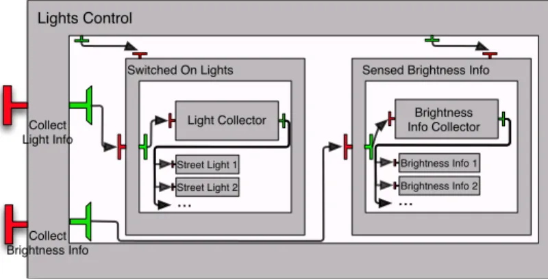
In the realm of autonomic computing one must be able to dynamically re-structure the architecture of the application. In [5] we showed how structural reconfigurations were used in order to provide a cost-efficient solution for the saving of power consumption. A slightly simplified architecture5 of the
pro-posed GCM application is depicted by Fig. 5.
Lights Control Collect Brightness Info Collect Light Info Switched On Lights Street Light 1 Street Light 2 ... Light Collector
Sensed Brightness Info
Brightness Info Collector
Brightness Info 1 Brightness Info 2
...
Fig. 5 Use-Case Architecture
This use-case consists in an experimental component system in charge of switching on and off street lights, according to the perceived luminosity of the surroundings. Basically, in order to address the goal of saving energy, but at the same time offering an acceptable quality of service (i.e. an acceptable luminosity in the streets), the components Street Light and Brightness Info are added/removed accordingly. Moreover, as said in [5], the use-case starts with three Brightness Info components and zero Street Light component.
5 GCM components possess a membrane part that we do not model in Mefresa. This
We shall model this scenario in Mefresa by defining every component in-volved in the architecture. For instance, components Light Collector and Street Light are mechanized as follows:
1 Component ( I d e n t ” L i g h t C o l l e c t o r ” ) Top p1 C o n f i g u r a t i o n 2 n i l 3 ( I n t e r f a c e ( I d e n t ” L i g h t I n f o ” ) Top 4 ( p1 ++ I d e n t ” L i g h t C o l l e c t o r ” : : n i l ) 5 E x t e r n a l S e r v e r F u n c t i o n a l I d l : : 6 I n t e r f a c e ( I d e n t ” C o l l e c t L i g h t I n f o ” ) Top 7 ( p1 ++ I d e n t ” L i g h t C o l l e c t o r ” : : n i l ) 8 E x t e r n a l C l i e n t F u n c t i o n a l I d l : : 9 n i l ) 10 n i l . 11 12 Component ( I d e n t ” S t r e e t L i g h t ” ) Top p1 C o n f i g u r a t i o n 13 n i l 14 ( I n t e r f a c e ( I d e n t ” Get ” ) Top 15 ( p1 ++ I d e n t ” S t r e e t L i g h t ” : : n i l ) 16 E x t e r n a l S e r v e r F u n c t i o n a l I d l : : 17 n i l ) 18 n i l .
In the above definitions, p1 is just a variable that represents the path of both components in the hierarchy. Furthermore, the remaining components are defined in a similar fashion and omitted for the sake of space. Considering the variable LightsControlUseCaseArchitecture as the structure holding the complete hierarchy, we can prove its well formedness.
1 Lemma L i g h t s C o n t r o l U s e C a s e i s w e l l f o r m e d : 2 w e l l f o r m e d L i g h t s C o n t r o l U s e C a s e A r c h i t e c t u r e .
The architecture from this use case indeed meets the specification, and proving this lemma poses no particular challenge as it has an explicit structure. The interesting aspect of this use-case comes from the fact that we need to add and remove components at runtime. Indeed, this scenario is yet another example of the usefulness of being able to cope with parametrized specifications.
Before proceeding to the structural reconfigurations, we shall use our oper-ation language constructs to define new, higher-level constructs. For instance, we can easily define an operation to build several components at a time:
1 F i x p o i n t mk components l c : o p e r a t i o n := 2 match l c w i t h
3 n i l => done
4 | c : : r => mk component c ; mk components r
5 end.
This new operation mk components takes a list of components as argument and produces a sequence of mk component operations by means of our ; con-structor. Further, we shall also define an operation for the construction of a list of bindings.
1 F i x p o i n t m k n o r m a l b i n d i n g s ( p : path ) ( i c c : i d e n t ) ( i i c : i d e n t )
2 ( i c s : i d e n t ) ( n : n a t ) ( i i s : i d e n t ) :=
3 match n w i t h
5 | S m =>
6 ( m k b i n d i n g ( Normal p i c c i i c ( s u f f i x i d e n t i c s n ) i i s ) ) ; 7 m k n o r m a l b i n d i n g s p i c c i i c i c s m i i s
8 end.
The rationale behind this apparently complex operation is as follows. Es-sentially, it is a set of bindings being made from the same client to several servers. The path p is given as pointer to the component in the hierarchy where the binding is going to be kept. Then, we specify the identifiers icc and iic that determine the component and interface from which the binding is made from. Since each binding will be made to a different component, we need to generate different identifiers. This is achieved in the same manner as with the generate from template function defined above: at each recursion step we suffix n to ics so that we target different components for every binding built. Finally, the identifier iis gives the interface to which the binding is made to.
Having defined our new operations, we can now proceed to the specification of the reconfiguration to add Street Light components. Below, LightComp is a variable representing our Street Light component defined above.
1 D e f i n i t i o n a d d l i g h t s r e c o n f i g ( n : n a t ) :=
2 mk components ( g e n e r a t e f r o m t e m p l a t e LightComp n ) ; 3 m k n o r m a l b i n d i n g s p1
4 ( I d e n t ” L i g h t C o l l e c t o r ” ) ( I d e n t ” C o l l e c t L i g h t I n f o ” ) 5 ( I d e n t ” S t r e e t L i g h t ” ) n ( I d e n t ” Get ” ) .
Basically, the above creates n components by using the Street Light compo-nent as template, and then establishes the required bindings. This, could for instance be used as follows:
1 Lemma a d d i n g l i g h t s r e d : 2 e x i s t s s , a d d l i g h t s r e c o n f i g 3 / L i g h t s C o n t r o l U s e C a s e A r c h i t e c t u r e −−−>∗ Done / s . 3 4 Lemma a d d i n g l i g h t s : 5 f o r a l l s , 6 a d d l i g h t s r e c o n f i g 3 / L i g h t s C o n t r o l U s e C a s e A r c h i t e c t u r e −−−>∗ Done / s −> 7 w e l l f o r m e d s .
Proving the above lemmas is achieved by the same reasoning techniques as discussed above. Regarding the first lemma, the key ingredient here to note is that components are created before establishing the bindings — and thus bindings will indeed succeed to be established — and they are well formed since they are generated from a well formed template component. As such, reducing this operation to done is possible. It should be noted that while generalizing this lemma for n would require a proof by induction, it would still follow the same principle. As for the second lemma, it is a natural consequence of our validity theorem.
4 Related Work
Many approaches regarding the formalization of component models can be found in the literature. Yet, to the best of our knowledge this is the first work aiming at providing a mechanized framework that applies the correct-by-construction paradigm to the world of component-based engineering. Nev-ertheless, we must cite the work from Henrio et al. [12] on a framework for reasoning on the behaviour of GCM component composition mechanized in Isabelle/HOL [18]. Our approach is still considerably different in that we pro-vide a semantics for an operation language for the building and reconfiguration of GCM architectures.
Another work involving the use of a proof assistant is the work by Johnsen et. al. on the Creol framework [16]. Creol focuses on the reasoning of distributed systems by providing a high-level object oriented modelling language. Its op-erational semantics are defined in the rewriting logic tool Maude [9]. This work however does not contemplate architectural reconfigurations and follows a methodology in the style of a Hoare Logic.
Indeed, while the use of proof assistants is gaining notoriety, model-checking is still the de facto formal approach for both industrial and academic under-takings. Usually, some form of state machine model is used for the design of the intended system, and then a carefully chosen model-checker as back-end is employed as a decision procedure. For instance, in [15] Inverardi et. al. discusses CHARMY, a framework for designing and validating architectural specifications. It offers a full featured graphical interface with the goal of being more user friendly in an industrial scenario. Still, architectural specifications remain of static nature. The BIP (Behaviour, Interaction, Priority) framework [3] formalizes and specifies component interactions. It has the particularity of also permitting the generation of code from its models.
Moreover, a formal specification of the Fractal Component Model has been proposed in the Alloy specification language [17]. This work proves the con-sistency of a (set-theoretic) model of Fractal applications. Their goal was to clarify the inherent ambiguities of the informal specification presented in [8]. Their specification however, is constrained by the first-order relational logic nature of the Alloy Analyzer. In fact, they point to the use of the Coq Proof Assistant in order to overcome this limitation.
For last, from a more engineering point of view, we can refer the work around FPath and FScript [10]. FPath is a domain-specific language for the navigation and querying of Fractal architectures. FScript embeds the FPath language and acts as a scripting language for the specification of reconfigura-tions strategies. The main goal of this work however is to alleviate the need to interact with the low-level API. Further, reliability of these reconfigurations is ensured by run-time checking, while we are more concerned on providing guarantees statically.
5 Final Remarks and Future Work
In this paper we presented our work on a framework to reason about the struc-ture of GCM distributed applications mechanized in the Coq Proof Assistant. The main novelty of our approach lies in the use of an operation language that allows to build software architectures that are correct-by-construction. While we lose some of the automation offered by the usual approach followed by the use of model-checkers, relying on the expressiveness of the Coq Proof Assistant allows us to reason on issues that cannot be addressed by usual model-checking techniques.
The choice of a deep-embedding rather than a shallow approach for the definition of our operation language is also worth discussing. By explicitly using a datatype for the encoding of our operation language there is a clear identification of its syntax, letting no doubt on how operations can be com-posed. Further, our goal here is also to formalize the GCM specification, a deep-embedding emphasizes the operational semantics for the building and re-configuration of architectures.
Indeed, the definition of the GCM specification in natural language opens the door for several interpretations. Further, such a specification is supposed to be flexible and allow various conceivable implementations. Nevertheless, this article shows that it is possible and fruitful to formalize such an undertaking in a proof assistant like Coq. This also provides a case-study on the mechanization of component models in the context of interactive theorem proving. In fact, the need for such an approach was already discussed in [17] and partially addressed in our previous work [11].
Currently, we focus on the structural concerns of distributed component-based applications, but we aim to provide the means to reason on functional concerns as future work. Modelling communication and including functional specifications of component’s server interfaces are within our plans. To this end, the expressiveness found in interactive theorem provers could be used to cope with parametrized designs and infinite domains. For instance, in [19] Sprenger demonstrates the benefits of combining model-checking with the Coq Proof Assistant. It is shown how this integration can be used to handle infinite space states while still keeping the automation benefit of model-checking.
Preliminary experiments with the use of co-inductive definitions to model infinite traces let us believe in the feasibility of the approach. Moreover, our research project6 will also bring some new insights on the best approach to
combine structural and functional concerns in our mechanized framework.
References
1. Barros, T., Ameur-Boulifa, R., Cansado, A., Henrio, L., Madelaine, E.: Behavioural models for distributed fractal components. Annales des T´el´ecommunications 64(1-2), 25–43 (2009)
2. Barros, T., Cansado, A., Madelaine, E., Rivera, M.: Model-checking distributed com-ponents: The vercors platform. Electron. Notes Theor. Comput. Sci. 182, 3–16 (2007). DOI 10.1016/j.entcs.2006.09.028. URL http://dx.doi.org/10.1016/j.entcs.2006.09. 028
3. Basu, A., Bensalem, S., Bozga, M., Combaz, J., Jaber, M., Nguyen, T.H., Sifakis, J.:
Rigorous component-based system design using the bip framework. IEEE Software
28(3), 41–48 (2011)
4. Baude, F., Caromel, D., Dalmasso, C., Danelutto, M., Getov, V., Henrio, L., P´erez, C.: Gcm: a grid extension to fractal for autonomous distributed components. Annales des T´el´ecommunications 64(1-2), 5–24 (2009)
5. Baude, F., Henrio, L., Naoumenko, P.: Structural reconfiguration : an autonomic strat-egy for gcm components. In: Proceedings of The Fifth International Conference on Autonomic and Autonomous Systems: ICAS 2009 (2009)
6. Bertot, Y.: Coq in a hurry. CoRR abs/cs/0603118 (2006)
7. Boulifa, R.A., Halalai, R., Henrio, L., Madelaine, E.: Verifying safety of fault-tolerant distributed components. In: International Symposium on Formal Aspects of Component Software (FACS 2011), Lecture Notes in Computer Science. Springer, Oslo (2011) 8. Bruneton, E., Coupaye, T., Stefani, J.B.: The fractal component model (2004). URL
http://fractal.ow2.org/
9. Clavel, M., Dur´an, F., Eker, S., Lincoln, P., Mart´ı-Oliet, N., Meseguer, J., Talcott, C.: The maude 2.0 system. In: R. Nieuwenhuis (ed.) Rewriting Techniques and Applications (RTA 2003), no. 2706 in Lecture Notes in Computer Science, pp. 76–87. Springer-Verlag (2003)
10. David, P.C., Ledoux, T., L´eger, M., Coupaye, T.: Fpath and fscript: Language sup-port for navigation and reliable reconfiguration of fractal architectures. Annales des T´el´ecommunications 64(1-2), 45–63 (2009)
11. Gaspar, N., Madelaine, E.: Fractal `a la Coq. In: Conf´erence en Ing´enieriE du Logiciel. Rennes, France (2012). URL http://hal.inria.fr/hal-00725291
12. Henrio, L., Kamm¨uller, F., Khan, M.U.: A framework for reasoning on component composition. In: FMCO 2009, Lecture Notes in Computer Science. Springer (2010) 13. Henrio, L., Rivera, M.: Stopping safely hierarchical distributed components: application
to gcm. In: CBHPC ’08: Proceedings of the 2008 compFrame/HPC-GECO workshop on Component based high performance, pp. 1–11. ACM, New York, NY, USA (2008). DOI http://doi.acm.org/10.1145/1456190.1456201
14. Hnetynka, P., Plasil, F.: Dynamic reconfiguration and access to services in hierarchical component models. In: Proceedings of CBSE 2006, Vasteras, Sweden, LNCS 4063, pp. 352–359. Springer-Verlag (2006)
15. Inverardi, P., Muccini, H., Pelliccione, P.: Charmy: An extensible tool for architectural analysis. In: ESEC-FSE’05, The fifth joint meeting of the European Software Engi-neering Conference and ACM SIGSOFT Symposium on the Foundations of Software Engineering. Research Tool Demos (2005)
16. Johnsen, E.B., Owe, O., Yu, I.C.: Creol: A type-safe object-oriented model for dis-tributed concurrent systems. Theoretical Computer Science 365(1–2), 23–66 (2006) 17. Merle, P., Stefani, J.B.: A formal specification of the Fractal component model in
Alloy. Rapport de recherche RR-6721, INRIA (2008). URL http://hal.inria.fr/
inria-00338987
18. Nipkow, T., Paulson, L.C., Wenzel, M.: Isabelle/HOL — A Proof Assistant for Higher-Order Logic, LNCS, vol. 2283. Springer (2002)
19. Sprenger, C.: A verified model checker for the modal mu-calculus in coq. In: In TACAS, volume 1384 of LNCS. Springer Verlag (1998)