HAL Id: hal-03034462
https://hal.archives-ouvertes.fr/hal-03034462
Submitted on 10 Dec 2020
HAL is a multi-disciplinary open access
archive for the deposit and dissemination of
sci-entific research documents, whether they are
pub-lished or not. The documents may come from
teaching and research institutions in France or
abroad, or from public or private research centers.
L’archive ouverte pluridisciplinaire HAL, est
destinée au dépôt et à la diffusion de documents
scientifiques de niveau recherche, publiés ou non,
émanant des établissements d’enseignement et de
recherche français ou étrangers, des laboratoires
publics ou privés.
The Brownian and Flow-Driven Rotational Dynamics of
a Multicomponent DNA Origami-Based Rotor
Yasaman Ahmadi, Ashley Nord, Amanda Wilson, Christiane Hütter, Fabian
Schroeder, Morgan Beeby, Ivan Barišić
To cite this version:
Yasaman Ahmadi, Ashley Nord, Amanda Wilson, Christiane Hütter, Fabian Schroeder, et al.. The
Brownian and Flow-Driven Rotational Dynamics of a Multicomponent DNA Origami-Based Rotor.
Small, Wiley-VCH Verlag, 2020, 16 (22), pp.2001855. �10.1002/smll.202001855�. �hal-03034462�
www.small-journal.com
The Brownian and Flow-Driven Rotational Dynamics
of a Multicomponent DNA Origami-Based Rotor
Yasaman Ahmadi, Ashley L. Nord, Amanda J. Wilson, Christiane Hütter,
Fabian Schroeder, Morgan Beeby, and Ivan Barišić*
Y. Ahmadi, C. Hütter, Dr. I. Barišić Molecular Diagnostics
Centre for Health and Bioresources AIT Austrian Institute of Technology GmbH Giefinggasse 4, Vienna 1210, Austria E-mail: Ivan.Barisic@ait.ac.at
DOI: 10.1002/smll.202001855
and catalytic mechanisms.[3] Other
exam-ples include rotational dynamics of viruses while binding to ligands on lipid mem-branes,[4] the active rotation of
micropar-ticles during uptake by microphage cells[5]
and the spiral rotational walking trajectory of kinesin while trafficking cargos along microtubules.[6]
Mimicking the translational or rotary dynamics functionality of natural protein motors is of great interest, with applica-tions ranging from synthetic biology to drug delivery and nanorobotics. Inspired by nature, supramolecular chemists have synthesized a wide variety of artificial molecular machines.[7] The most studied
class of man-made molecular machines are rotaxanes; mechanically interlocked molecules that possess a similar topology as the ATP synthase and the bacterial flagellar motor.[8,9] Synthetic molecular
machines are simple and rather small compared to natural biological molecular machines. An alternative strategy for the realization of mole-cular machines, which resemble natural protein motors in size and shape, is DNA nanotechnology. The sequence-specific interaction of DNA allows the programmable self-assembly of custom designed 2D and 3D structures at the nanoscale level.[10,11] The invention of the DNA origami technique enabled
the realization of almost any desired topology and geometry using a long circular single stranded scaffold and hundreds of shorter shape-determining synthetic staple strands.[12] The most
Nanomechanical devices are becoming increasingly popular due to the very diverse field of potential applications, including nanocomputing, robotics, and drug delivery. DNA is one of the most promising building materials to realize complex 3D structures at the nanoscale level. Several mechanical DNA origami structures have already been designed capable of simple opera-tions such as a DNA box with a controllable lid, bipedal walkers, and cargo sorting robots. However, the nanomechanical properties of mechanically interlinked DNA nanostructures that are in general highly deformable have yet to be extensively experimentally evaluated. In this work, a multicompo-nent DNA origami-based rotor is created and fully characterized by electron microscopy under negative stain and cryo preparations. The nanodevice is further immobilized on a microfluidic chamber and its Brownian and flow-driven rotational behaviors are analyzed in real time by single-molecule fluo-rescence microscopy. The rotation in previous DNA rotors based either on strand displacement, electric field or Brownian motion. This study is the first to attempt to manipulate the dynamics of an artificial nanodevice with fluidic flow as a natural force.
The ORCID identification number(s) for the author(s) of this article can be found under https://doi.org/10.1002/smll.202001855.
Y. Ahmadi
Department for Biotechnology
University of Natural Resources and Life Sciences Muthgasse 18, Vienna 1190, Austria
Dr. A. L. Nord
Centre de Biochimie Structurale (CBS) CNRS
INSERM
Univ Montpellier, 29 Rue de Navacelles, Montpellier 34090, France Dr. A. J. Wilson, Dr. M. Beeby
Department of Life Sciences Imperial College London London SW7 2AZ, UK Dr. F. Schroeder Computational Statistics Technical University of Vienna Karlsplatz 13, Vienna 1040, Austria
1. Introduction
The translational and rotational dynamics are an inherent feature of many cellular processes.[1] While researchers have
typically focused on investigating translational dynamics, a growing number of recent studies exhibit the prevalence of rotational dynamics in biological processes.[2] For example, in
the F0F1-ATP synthase complex, the rotary movement of an assembly of subunits plays essential roles in both transport
© 2020 The Authors. Published by WILEY-VCH Verlag GmbH & Co. KGaA, Weinheim. This is an open access article under the terms of the Creative Commons Attribution-NonCommercial-NoDerivs License, which permits use and distribution in any medium, provided the original work is properly cited, the use is non-commercial and no modifications or adaptations are made.
www.advancedsciencenews.com www.small-journal.com
studied DNA-based artificial machines are DNA walkers.[13] The
walking molecular devices mostly rely on DNA strand displace-ment,[14] however other sources of energy such as ATP[15] and
light[16] have also been used for triggering the walking
mecha-nism. A sophisticated version of such DNA walkers is a cargo-sorting robot capable of picking up multiple cargos at unor-dered locations and delivering each to a specified destination.[17]
DNA origami-based rotaxanes[18,19] and a DNA origami box with
a controllable lid[20] were also reported. These DNA-based
mole-cular machines were designed to mimic transient dynamics. A few recent studies have addressed the rotational mimicry, including a rotary DNA origami device with a stepping opera-tion using strand displacement,[21] a robotic arm controlled
by an electric field,[22] and a tight-fitting passive DNA origami
rotary apparatus only influenced by Brownian motion.[23]
How-ever, no studies to date have attempted to apply natural forces such as fluidics to manipulate the rotational mechanism of molecular machines. Herein, we used the DNA origami tech-nique to create a rotary device compromising four individual elements. The Brownian and flow-driven rotary movements of the DNA origami device were investigated in a microfluidic chamber by single-molecule TIRF microscopy. Our work pro-vides the experimental framework for real-time in vitro evalua-tions of flow-driven nanodevices, discusses the challenges, and suggests ways for improvements for similar systems.
2. Results and Discussion
The nanoscale rotary prototype is composed of four different multilayer DNA origami components (Figure 1): a “propeller” attached to an “inner-rotor” which is encircled by a “two-component stator.” The propeller is a two-layer square lattice DNA origami with ≈350 nm × 4 nm × 8 nm dimensions. Six fluorescently labeled (Atto488) staple strands were incorporated at the edge of the propeller to allow the tracking of the rota-tion by single-molecule fluorescence microscopy. The rotor body – composed of the inner-rotor encircled by a two-component stator – is a trimer with a hexagonal cross section and is ≈50 nm long with an outer width of ≈40 nm. Ten staple strands including 5´ or 3´ thiol modifications were extended from the lower helices of the stator to promote the immobilization of the rotary device on maleimide-modified glass coverslips. To con-nect the separately self-assembled DNA origami components into a higher-order DNA machinery (super-assembly), the bridging strand method was used to allow precise positioning. These bridging strands are staple strands (with complemen-tary sequences to the scaffold) in both to-be-connected origami pairs (refer to Sections S1–S6 in the Supporting Information for detailed instructions). For super-assembly, we first docked the inner-rotor into the two-element stator to build the rotor body (Figure 1A,B). The bridging strands connecting the inner-rotor to the stator additionally comprise an internal photo-cleavable spacer (iSpPC). The propeller was then connected to the inner-rotor (encircled by the stator) via six bridging strands (Figure 1C). Upon exposing the super-assembled DNA rotary device to the UV light in the 300–350 nm spectral ranges, the iSpPC-modified strands were cleaved, and the inner-rotor (con-nected to the propeller) was free to rotate. The success of self- and
super-assembly was monitored by analyzing the mobility of the structures on agarose gel electrophoresis (AGE) and by imaging with transmission electron microscopy using negative stain preparation (nsTEM). For all structures self-assembled in a buffer supplemented with 14–20 × 10−3 m MgCl
2 in a one-day
thermal ramp, a band migrating faster than the scaffold was observed (Section S7, Supporting Information). Imaging by nsTEM further verified that these bands belong to correctly folded origami structures (Section S8, Supporting Information). The self-assembled DNA origami structures were successfully purified from excess staple strands by the PEG precipitation method (Section S7, Supporting Information).[24] Mobility
analysis by AGE also offers a straightforward and quick method to track the success of the di- and tri-merization of origami struc-tures. The origami dimers could be easily detected by observing a band, which migrated slower than each of the individual ori-gami structures. The rotor body trimer migrated slower than the corresponding dimers (Section S9, Supporting Informa-tion). The origami dimers and trimers, and the full rotary device (a tetramer) were successfully imaged by nsTEM (Figure 1E–L and Figure S10, Supporting Information). Although differen-tiating between, e.g., the “rotor body” trimer from the dimer counterparts was rather difficult (since the structures tend to lay on their side on the TEM grid), observing structures from a top view allowed an accurate recognition (Figure 1G,L).
To assess a correct 3-D super-assembly of the rotor body (complex of inner-rotor and stator), we imaged DNA origami structures under cryo conditions. An optimization of the sam-pling grid involving the addition of a thin layer of carbon leads to an excellent particle dispersion (Figure 2A,B). Nevertheless, we found it necessary to image rotor particles in holes without carbon to acquire end-views for 3D reconstruction. Image pro-cessing using RELION produced 2-D class averages (Figure 2C) and a 3D reconstruction (Figure 2D). Building on our results, we developed conditions for high-yield particle fields of the rotor body (Figure 2E) and used these images to determine 2-D class averages (Figure 2F). Intriguingly, the 2-D class averages, as well as individual projection images, revealed a rigid, well-defined inner-rotor structure but a more flexible two-component stator barrel (Figure 2E,F). To better characterize this flexibility, we measured the widths of the stator barrel in a number of individual projection images. By measuring the width of the two-component stator barrel as a function of height along the inner-rotor (from the top to the middle to the base), we found that the stator barrel varied in width at the top from between 42 to 52 nm and at the base from 46 to 54 nm. Furthermore, these widths tended to be correlated—in other words, if the stator barrel was wider at the base, it was also wider at the tip; if the stator barrel was narrower at the base, it was also wider at the tip. This correlation was a trend, however, and not rig-idly adhered to (Section S11, Supporting Information). For example, one exceptional stator barrel was 52 nm wide at the tip, narrowing to 46 nm at the base. We concluded that the stator barrel is flexible, manifesting as a moderately-resolved stator barrel structure in a 3-D reconstruction (Figure 2G). Despite flexibility, however, our micrographs and class averages demonstrated that the assembly yield was high, with partially-assembled structures being rare. Significantly, we noted that the rate of increase in diameter increases in some (but not all)
structures between the middle and bottom, suggesting greater flexibility of the bottom of the complex, and consistent with the diameter of the bearing cavity being sufficiently large to permit rotation of the rotor.
The DNA origami rotor was then immobilized on the maleimide functionalized coverslips. A microfluidic chamber was then added to the coverslip. Afterward the chamber was connected to a pump. We hypothesized that the buffer
Figure 1. A) The inner-rotor is ensembled to the first element of the stator through ten photolabile bridging staple strand (iSpPC). B) The resulting
dimer is then connected to the second element of the stator, facilitated by three iSpPC-modified bridging strands and also by interaction of the two stator elements through “shape complementary” and “hybridizing strands.” C) Six bridging strands protruding from the center of the propeller mediate the connection to the (top of) inner-rotor. D) To trap the rotor in the stator cavity, a few staple strands were protruded across the stator elements, and were then hybridized via a third sequence-complementary oligonucleotide. After immobilizing the rotary devices on the coverslips, they were exposed to UV light in the 300–350 nm spectral ranges to cleave the iSpPC-modified strands to allow a free rotation of the inner-rotor. Negative stain (nsTEM) micrographs of E) dimer of inner-rotor and the first element of the stator; F) dimer of the inner-rotor and the propeller; G) two-element stator barrel, top view; H) trimer of inner-rotor encircled by the stator (rotor body); I) trimer of inner-rotor, propeller and first stator element; J) and K) side views of tetrameric rotary devices, L) top view of the rotary device. All nsTEM images represent structures before cleavage by UV light. Scale bars, 50 nm.
www.advancedsciencenews.com www.small-journal.com
circulating in the chamber should have an impact on the Brownian rotational behavior of the rotor induced by Brownian motion. We visualized the rotor by single-molecule fluorescence micro scopy in TIRF mode at different flow rates. In parallel to the DNA machinery (Figure 1J–L), the dimer of “inner-rotor and propeller” was tested as the control (Figure 1F). The dimer was immobilized on the coverslip through three thiol modified staple strands, which protruded from the lower helices of the inner-rotor. As the inner-rotor was stuck to the surface, only a limited rotational swinging should be feasible.
The small size of the DNA origami rotor means that the rotational Brownian diffusion will be rapid. Given the geom-etry of the DNA origami rotor, we estimated an upper limit for the rotational diffusion coefficient as 277 s−1 (see Section S12,
Supporting Information). These calculations indicate that tem-poral resolution of the rotational dynamics of this rotor would be challenging. Moreover, the fluorescent dyes traverse a circle of 350 nm diameter, near the limit of optical resolution. Given these challenges, we have left the full spatio-temporal resolu-tion and characterizaresolu-tion of rotaresolu-tional dynamics to future work. Researchers investigating such rotational DNA machines have previously achieved spatial and temporal resolution of rotation dynamics by slowing rotation. In a recent paper by Kosuri et al.,[25] DNA-processing enzymes that rotate in a
step-wise manner were attached to a DNA rotor allowing an analysis of the rotational dynamics. Other approaches to reduce rotational
diffusion could include heightened surface interaction, altera-tions of rotor geometry, the addition of a larger nano particle for tracking, or increasing buffer viscosity. An alternative approach would be to attach an anisotropic particle to the propeller. Particle probes that are anisotropic in shape, such as quantum or gold rods, or in optical properties, such as fluores-cent microspheres, have classically been used to track rotational dynamics in natural protein motors.[1] However, such particles
are relatively large (≈60 nm) and immobilizing them at the edge of a 350 nm long propeller may disturb the balance of the nanomachine. Additionally, as DNA is not a rigid material and DNA nanostructures are strongly influenced by the sur-rounding ion composition (swelling effects, retention), many of the above-mentioned modifications may alter the nano-mechanical properties of DNA nanostructures.
Here, we aimed to avoid any massive molecular modifica-tions of the rotor, and we sought to use single molecule micros-copy to give general insight into its rotational mobility. From the rotor geometry and EM structures, we predict that the rotor can rotate freely between three preferred rotational states (Figure 2G). The videos captured 800–2000 frames with an exposure time of 10 ms. Thunderstorm, a plugin for image J for data analysis of super-resolution data,[26] was used to localize
the position of the propeller-attached fluorophores in each frame of the video. The dispersion of these localizations, as cal-culated by the radial standard deviation, was used as a simply
Figure 2. Cryo-EM micrographs of the inner-rotor and rotor body. A) imaging of inner-rotor particles in vitreous ice on holey carbon films with end
views in the hole. B) Imaging of inner-rotor particles in vitreous ice in holey carbon films with an additional layer of thin carbon yields side views. C) 2D class averages of inner-rotor particles. D) 3D class of inner-rotor particle from side (left of panel) and top (right of panel). E) Top and side views of rotor body particles in vitreous ice. F) 2D and G) 3D class averages of rotor body particles illustrating correct assembly despite flexibility of the stator barrel. The stator barrel is poorly resolved due to flexibility. Scale bars, 100 nm.
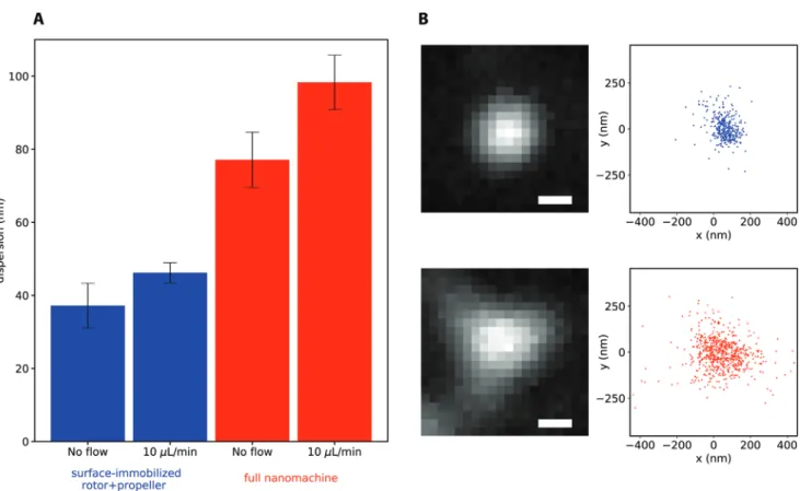
proxy for the mobility of the rotor. We observed a higher degree of mobility in the fully assembled nanomachine as compared to the surface-immobilized inner-rotor/propeller, and this mobility increased slightly under moderate flow (10 µL min−1), as shown
in Figure 3. The localization patterns of the nanomachines ranged from radially symmetric, to elongated, to triangular; we speculate that the latter, an example of which is shown in Figure 3b, is indicative of a rotor rotating freely between the three rotational states (Section S13, Supporting Information). In order to analyze the correlation between the flow rate and the rotational behavior, we performed experiments under dif-ferent flow rates: 5, 10, 20, 40, 60, and 100 µL min−1. At a low
5 µL min−1 flow rate, no significant difference compared to no
flow conditions was observed. At higher flow rates (particularly over 40 µL min−1), we needed to constantly refocus the lenses
due to the perturbation in the system. This made it impos-sible to properly analyze the data at higher flow rates. Hence, a significantly more sophisticated hardware setup is required to observe the change in rotational behavior over increasing or decreasing flow rates in the nanoscale.
3. Conclusions
In summary, we constructed a structurally well-defined multi-complement DNA origami-based rotary device, and analyzed
its Brownian and flow-driven rotational dynamics by single-molecule microscopy in a microfluidic chamber set-up. The rotor can randomly switch among three different rotational states, and its mobility increases under moderate flow rates, however the rotor cannot achieve controllable rotation. To our best knowledge, this is the first nanodevice assembled from four different DNA origami nanostructures. While our study is the first to use fluidic as the natural force for manipulating the dynamics of an artificial nanodevice, using ATP -as the predominant natural source of energy–to produce linear or rotary motion is essential to build sophisticated machinery prototype with efficiencies rivalling those of natural protein machines. Recent advancements in creation of DNA-protein hybrid nanoscale shapes,[27,28] and DNA- templated assembly
of peptides[29] and proteins such as the cytoplasmic ring of the
bacterial flagellar motor[30] are inspiring in building artificial
nanodevices resembling natural protein motors in structure and function. We have also recently emulated the catalytic activity of an ATP-driven FlaI protein motor by identifying and embedding a set of catalytically essential amino acids into the DNA stator barrel in Figure 1G.[31] Translating the ATPase
activity of such embedded catalytic proteins into the mechan-ical movement is the main challenge to address. Addition-ally, the propeller of our rotary device could be functionalized with antibodies or aptamers and further exploited as label-free biosensor.
Figure 3. Single molecule localizations of the propeller-attached fluorophores. A) The average and standard error of the mean (SEM, error bars) of
the localization dispersion, defined as the radial standard deviation, for the surface-attached inner-rotor/propeller (blue), and the fully assembled nanomachine (red). The number of measurements within each bar, from left to right, were 5, 6, 18, and 16. B) Example measurements at 10 µL min−1
flow. The sum of the video frames (left), and the single molecule localizations (right), for the dimer of inner-rotor/propeller (top), and fully assembled nanomachine (bottom). Scale bars, 436 nm.
www.advancedsciencenews.com www.small-journal.com
4. Experimental Section
Materials: PEG 8000 was purchased from Carl Roth GmbH (Germany).
SYBER Safe and DNA gel loading dye (6x) (catalog number: R0611) were purchased from Thermo Fischer scientific. The HybriWell Sealing System (HBW4545, 1–45 mm × 45 mm × 0.15 mm Depth, chamber volume 110 µL approximately Vol., 51 mm × 56 mm OD, SecureSeal) and press Fit Tubing connectors were purchased from Grace BIO-LABS. Cover slips (24 × 60 mm, ≠1.5) were purchased from Menzel Glaser (Germany). All oligonucleotides were ordered from IDT Integrated DNA Technologies. Staple strands were ordered in in 100 × 10−6 m concentration (desalted)
in DNase free water. HPLC purified, fluorescently labeled (Atto488) staple strands and thiol modified (ThioMC6-D) staple strands were ordered. Photo-cleavable iSpPC modified oligonucleotides were PAGE purified.
Design, Self-Assembly and Purification of Nanostructures: The
nanostructures were designed in an iterative procedure using the caDNAno software (version 2.2.0)[32] and CanDo.[33] The propeller and
inner-rotor were modified based on two similar origami structures from the previous publications.[34,35] The cross-section view and blue prints of
all DNA origami structures are illustrated in Sections S2–S6 (Supporting Information). For self-assembly, scaffold (10 × 10−9 m) and staple
strands (100 × 10−9 m) were mixed in 100 µL Tris buffer (5 × 10⁻³ m Tris,
1 × 10⁻³ m EDTA, 5 × 10⁻³ m NaCl) containing variable concentration of
MgCl2 (12 -26 × 10−3 m). All staple strands were not purified (desalted),
except modified staple strands, which were ordered in PAGE or HPLC purification scale and were added in 200 × 10−9 m concentration
(20-fold) compared to the scaffold during the self-assembly of each structure. Annealing was performed by exposing the reaction to 65 °C for 15 min and then cooling down from 65 to 25 °C by 1 °C every 40 min in a 23 h thermal ramp. The nanostructures were purified using the PEG precipitation method.[24] For this aim, 100 µL of DNA origami
samples in Tris buffer (5 × 10⁻³ m Tris, 1 × 10⁻³ m EDTA, 5 × 10⁻³ m NaCl)
including 18 × 10−3 m MgCl
2 were mixed with an equivalent volume
of 22 × 10−3 m MgCl
2 supplemented Tris buffer followed by adding
200 µL PEG precipitation buffer (15% w/v PEG 8000, 5 × 10⁻³ m Tris,
1 × 10⁻³ m EDTA and 505 × 10−3 m NaCl). The solution was then mixed
gently by tube inversion and centrifuged at 16 000 × g at r.t for 25 min. The supernatant was carefully discarded, and the pellet was dissolved in the experimentally determined optimal buffer and incubated for one day at r.t at 650 rpm.
Super-Assembly of DNA Machinery: The super-assembly of the
DNA machinery was performed in Tris buffer supplemented with 16 × 10−3 m MgCl
2 based on the following procedure: i) incubation of the
inner-rotor with the first element of the stator in a stoichiometry of 1:1 at 37 °C for one day, ii) addition of the second element of the stator in a stoichiometry of 1:1 at 37 °C for one day, iii) addition of the propeller in a stoichiometry of 1:1 at 37 °C for one day, iv) adding hybridizing strands for closing the rotor body cavity in a stoichiometry of 10:1 per binding site and incubation at 25 °C for one day. All incubation steps were at 650–700 rpm.
Mobility Analysis by Agarose Gel Electrophoresis (AGE): The gel
electrophoresis was performed in 1.5–2% agarose gels supplemented with 11 × 10−3 m MgCl
2 and SYBER safe DNA gel stain in TAE buffer
(0.5 ×) at pH 8. The sample of interest was mixed with 20% loading buffer (6 ×) and then loaded into agarose gel wells. The gel was run at 70 V for 2.5–3 h and visualized using the UVP scanner.
Negative Staining Transmission Electron Microscopy (nsTEM): The
morphological examination of nanostructures was done using a transmission electron microscope (TEM) performed on a Morgagni operated at 80 kV. The images were taken by a Morada camera. Samples were prepared by dropping 5 µL of diluted nanostructures on a glow-discharged carbon-coated Cu400 TEM grid and negative staining using 2% uranyl acetate.
Cryo-Imaging: 2.5 µL DNA nanostructure solutions were applied to plasma-cleaned R2/2 Quantifoil grids with or without an additional 5 nm carbon coating in a Vitrobot Mk. 4 (FEI) using a wait time of
60 s, blot time 2 s, blot force 3, and drain time of 1 and plunged into ethane cryogen. Grids were stored under liquid nitrogen until imaging. Image frames were acquired on a Falcon II direct electron detector (FEI) with pixel size 2.05 Å on an FEI Tecnai F20 cryo-microscope using EPU software using a cumulative electron dose of 35 e− Å−2. All processing
was performed in the Scipion environment. Defocus was determined using CTFFIND4, particles initially picked manually using Xmipp followed by autopicking, the 2-D and 3-D class averages produced using RELION 2.1 using default parameters.
Preparation of Maleimide Coated Cover Slips and Immobilizing the Rotary Device: The maleimide-functionalized coverslips were prepared
using an in-house method (refer to Section S14, Supporting Information for detailed instructions). A HybriWell sealing system or a glass slide was added to the maleimide modified coverslip to create a microfluidic chamber. The press fit tubing connectors were then fitted to connect the chamber to the pump. The DNA nanostructures or the gold NPs were then added to the chamber and incubated for 1 h. The unreacted sample was then washed away through flushing the chamber with 16 × 10−3 m
MgCl2 supplemented Tris buffer.
Single-Molecule Fluorescence Microscopy: The experiments were
performed using objective-type total internal reflection fluorescence (TIRF) single-molecule microscopy. The microscope set-up was as follows: AxiTIRF (excitation 488 nm, cobalt (100 mV laser), 10 ms exposure time. Camera (Andor iXon, EM-CCD), pixel size = 109 nm (512 × 512 pixels), NA: 1.49 and oil immersion /resolution of microscope = 550/2 × 1.49 (NA) = 184 nm resolution with localization ≤100 nm, SOLIS software, Olympus UAPON (NA = 1.49, mag = 100x) with true magnification (125/50)x100 = 250 through relay system (f = 50 mm and f = 125 mm). The videos capture was 800–2000 frames with an exposure time of 10 ms. The data were then analyzed using Thunderstorm.[26]
Supporting Information
Supporting Information is available from the Wiley Online Library or from the author.
Acknowledgements
This project has received funding from the European Union’s Horizon 2020 research and innovation programme under grant agreement No. 686647. nsTEM images were recorded at the EM Facility of the Vienna Biocenter Core Facilities GmbH (VBCF). Y.A. and I.B. thank Dr. Kareem Elsayad at the Advanced Microscopy facility at VBCF for access and assistance in performing TRIF microscopy. M.B. and A.J.W. thank Teige Matthews-Palmer and Paul Simpson for electron microscopy advice and assistance.
Conflict of Interest
The authors declare no conflict of interest.
Author Contributions
Y.A. designed the DNA origami structures and performed laboratory experiments for creation of DNA rotary device, nsTEM imaging and TIRF microscopy. Y.A., A.L., and F.S. analyzed the fluorescence microscopy data. A.J.W. and M.B. performed cryo imaging. C.H. prepared the Maya models and assisted in the in silico design of rotary device and preparing the figures. I.B. designed the research and perceived the study. Y.A., A.L., M.B., and I.B. prepared the figures and wrote the manuscript.
Keywords
DNA nanotechnology, DNA origami, flow-driven rotational dynamics, molecular devices
Received: March 20, 2020 Published online: May 3, 2020
[1] Y. Gao, Y. Yu, L. Sanchez, Y. Yu, Micron 2017, 101, 123. [2] S. M. Anthony, Y. Yu, Anal. Methods 2015, 7, 7020.
[3] R. K. Nakamoto, J. A. Baylis Scanlon, M. K. Al-Shawi, Arch. Biochem.
Biophys. 2008, 476, 43.
[4] P. Kukura, H. Ewers, C. Müller, A. Renn, A. Helenius, V. Sandoghdar,
Nat. Methods 2009, 6, 923.
[5] L. Sanchez, P. Patton, S. M. Anthony, Y. Yi, Y. Yu, Soft Matter 2015,
11, 5346.
[6] M. Brunnbauer, R. Dombi, T. H. Ho, M. Schliwa, M. Rief, Z. Ökten,
Mol. Cell 2012, 46, 147.
[7] M. A. Watson, S. L. Cockroft, Chem. Soc. Rev. 2016, 45, 6118. [8] C. A. Schalley, K. Beizai, F. Vögtle,, Acc. Chem. Res. 2001, 34, 465. [9] Y. Sowa, R. M. Berry, Q. Rev. Biophys. 2008, 41, 103.
[10] M. R. Jones, N. C. Seeman, C. A. Mirkin, Science 2015, 347, 1260901.
[11] S. M. Duglas, H. Dietz, T. Liedl, B. Högberg, F. Graf, W. M. Shih,
Nature 2009, 459, 414.
[12] P. W. K. Rothemund, Nature 2006, 440, 297.
[13] J. Pan, F. Li, T. G. Cha, H. Chen, J. H. Choi, Curr. Opin. Biotechnol.
2015, 34, 56.
[14] J. S. Shin, N. A. Pierce, J. Am. Chem. Soc. 2004, 126, 10834. [15] P. Yin, H. Yan, X. G. Daniell, A. J. Turberfield, J. H. Reif, Angew.
Chem., Int. Ed. 2004, 43, 4906.
[16] M. You, Y. Chen, X. Zhang, H. Liu, R. Wang, K. Wang, K. R. Williams, W. Tan, Angew. Chem., Int. Ed. 2012, 51, 2457.
[17] A. J. Thubagere, W. Li, R. F. Johnson, Z. Chen, S. Doroudi, Y. L. Lee, G. Izatt, S. Wittman, N. Srinivas, D. Woods, E. Winfree , L. Qian,
Science 2017, 357, eaan6558.
[18] J. List, E. Falgenhauer, E. Kopperger, G. Pardatscher, F. C. Simmel,
Nat. Commun. 2016, 7, 12414.
[19] J. T. Powell, B. O. Akhuetie-Oni, Z. Zhang, C. Lin, Angew. Chem., Int.
Ed. 2016, 55, 11412.
[20] E. S. Andersen, M. Dong, M. M. Nielsen, K. Jahn, R. Subramani, W. Mamdouh, M. M. Golas, B. Sander, H. Stark, C. L. P. Oliveira, J. S. Pedersen, V. Birkedal, F. Besenbacher, K. V. Gothelf, J. Kjems,
Nature 2009, 459, 73.
[21] T. Tomaru, Y. Suzuki, I. Kawamata, S. I. M. Nomura, S. Murata,
Chem. Commun. 2017, 53, 7716.
[22] E. Kopperger, J. List, S. Madhira, F. Rothfischer, D. C. Lamb, F. C. Simmel, Science 2018, 359, 296.
[23] P. Ketterer, E. M. Willner, H. Dietz, Sci. Adv. 2016, 2, e1501209. [24] E. Stahl, T. G. Martin, F. Praetorius, H. Dietz, Angew. Chem., Int. Ed.
2014, 53, 12735.
[25] P. Kosuri, B. D. Altheimer, M. Dai, P. Yin, X. Zhuang, Nature 2019,
572, 136.
[26] M. Ovesný, P. Křížek, J. Borkovec, Z. Švindrych, G. M. Hagen,
Bioin-formatics 2014, 30, 2389.
[27] F. Praetorius, H. Dietz, Science 2017, 355, eaam5488. [28] K. Zhou, Y. Ke, Q. Wang, J. Am. Chem. Soc. 2018, 140, 8074.
[29] J. Jin, E. G. Baker, C. W. Wood, J. Bath, D. N. Woolfson, A. J. Turberfield, ACS Nano 2019, 13, 9927.
[30] J. Spratt, PhD thesis, University of Oxford, 2018.
[31] T. Kekić, Y. Ahmadi, I. Barišić, Preprint at biorxiv https://t.co/tBH-V6R1UYh 2019.
[32] S. M. Douglas, A. H. Marblestone, S. Teerapittayanon, A. Vazquez, G. M. Church, Nucleic Acids Res. 2009, 37, 5001.
[33] D. N. Kim, F. Kilchherr, H. Dietz, M. Bathe, Nucleic Acids Res. 2012,
40, 2862.
[34] Y. Ahmadi, E. De Llano, I. Barišić, Nanoscale 2018, 10, 7494. [35] Y. Ahmadi, I. Barisic, J. Vis. Exp. 2019, 143, e58771.