HAL Id: hal-03252838
https://hal.univ-lorraine.fr/hal-03252838
Submitted on 7 Jun 2021
HAL is a multi-disciplinary open access
archive for the deposit and dissemination of
sci-entific research documents, whether they are
pub-lished or not. The documents may come from
teaching and research institutions in France or
abroad, or from public or private research centers.
L’archive ouverte pluridisciplinaire HAL, est
destinée au dépôt et à la diffusion de documents
scientifiques de niveau recherche, publiés ou non,
émanant des établissements d’enseignement et de
recherche français ou étrangers, des laboratoires
publics ou privés.
Reliable FPGA-based Solar Energy Production
Ehsan Jamshidpour, Philippe Poure, Eskandar Gholipour Shahraki, Shahrokh
Saadate
To cite this version:
Ehsan Jamshidpour, Philippe Poure, Eskandar Gholipour Shahraki, Shahrokh Saadate. Reliable
FPGA-based Solar Energy Production. 7th International Congress of Energy and Environment
En-gineering and Management (CIIEM7), Jul 2017, Canary Islands, Spain. �hal-03252838�
Reliable FPGA-based Solar Energy Production
Ehsan Jamshidpour
ICube laboratory - UMR 7357
School of Engineering ECAM Strasbourg-Europe Strasbourg, France [email protected] Philippe Poure IJL Laboratory Université de Lorraine Nancy, France [email protected] E. Gholipour University of Isfahan Isfahan, Iran [email protected] Shahrokh Saadate GREEN Laboratory Université de Lorraine Nancy, France [email protected]
Abstract—This paper presents a stand-alone photovoltaic (PV) system with a hybrid storage unit operation under normal and faulty condition. An energy management method based on the use of a hybrid storage for the solar energy production system is presented. The storage system consists a battery and an Ultra Capacitor (UC) pack. The UCs are used for facing high frequency variation of the load/source, while the batteries are in charge of slow load /source variations. Generally, in a PV system boost converters are used to connect solar panels to the DC bus. These converter allows to achieve the maximum power of the PV source by applying a Maximum Power Point Tracking (MPPT) algorithm. On the other hand, the power electronic semiconductor switch faults are popular in DC-DC converters. In order to improve the micro-grid service continuity and reliability, a fast fault detection method based on the converter current shape and one redundancy based fault tolerant converter for PV source is proposed in this paper. The validity of the proposed energy management and associated control system, the fault detection method and fault tolerant strategy are confirmed by the simulations, HIL and experimental results.
Keywords—Solar energy; photovoltaic; energy management; hybrid power system; Fault detection; Fault tolerant.
I. INTRODUCTION
The last decades have shown a growing interest in DC-DC power conversion in industrial applications mainly in renewable energy power systems. Nowadays, islanded PV systems have a significant penetration in many applications such as space systems, telecommunication, solar battery charging stations, electric vehicles, meteorology stations, residential and commercial installations, as well as parts of hybrid power systems [1], [2]. In such embedded or safety critical applications, a high level of system reliability is mandatory [3]. In this paper two important issues that can affect the reliability and service continuity of the system are considered: energy management strategy and fault tolerant operation.
The energy balance on the common bus of the system is the first important criteria to have reliable normal operation. To ensure energy balance between sources and loads in a system, an effective energy management strategy is required.
Several papers have studied energy management methods in
microgrids [4]–[7]. In these works, different types of energy
sources, such as wind energy, fuel cell, photovoltaic, micro turbine and etc. are considered. The major challenge to use photovoltaic system as a main power supply is that PV power is not available during night and cloudy days. That is why the integration of the ESS is mandatory to reduce the uncertainty of the PV generation and to enhance the stability and reliability of such microgrids [4].
On the other hand, PV systems have a complex structure and are vulnerable to faults. A failure may occur in any part of the system such as PV panel, power converter or sensor. The DC-DC step-up converters that are usually used to perform MPPT in PV systems [8]-[10], have the failure rate up to 41% [11] where, the semiconductor failures take up 34% of power electronic
system failures [12]. Therefore, a fast Fault Detection Method (FDM) and Fault Tolerant (FT) operation for these converters should be proposed in PV systems reliability studies.
A few works have studied switch fault detection for isolated DC-DC converter and associated FT topologies, especially based on H-bridge as in [13], [14]. In [15], Ribeiro et al have proposed a switch FDM in DC-DC converters and FT converter topologies dedicated to PV systems. In [16], an Open Circuit Fault (OCF) detection method based on comparison of the duty cycle with the inductor current slope. In [17] and [18], a FPGA-based switch fault detection method for non-isolated DC-DC converter is proposed. This approach is based on the inductor current slope observation. The proposed method in [17] can detect both types of fault (OCF and Short Circuit Fault (SCF)) in two switching periods but cannot identify the type of failure, while, the proposed method in [18] identifies the both types of failures and it has fault tolerant capability. In [25], an alternative OCF diagnosis method for boost interleaved DC-DC converters operating in unidirectional power flow, using in PV system, is studied. This method is based on features of the DC-link current derivative sign during fault and healthy operations.
In this paper, an energy management strategy is studied and verified by simulation on a DC microgrid. The studied power system consists of a PV source, a battery pack, an ultra capacitor and some different loads, which are also connected to a common DC bus. Also a fast fault tolerant operation based on FPGA is proposed for the DC-DC converter of the PV source. The validity of the proposed method is confirmed be the experimental results.
In the following section, the studied system and its modeling is first introduced. In section III, the energy management strategy and system control are presented. Fault diagnosis and fault tolerant operation is expressed in section IV. Simulation and experimental results, which validate the performances of the proposed method, are presented in Section V. The paper is finalized by some conclusions in section VI.
II. SYSTEMDESCRIPTION AND SYSTEMMODELING
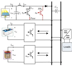
The studied system is shown in Fig. 1. This system consists of a photovoltaic (PV source) that is connected to the DC bus via a fault tolerant boost converter to guaranty the service continuity. A MPPT (Maximum Power Point Tracking) algorithm is applied on this boost converter to achieve the PV maximum produced power.
A model of moderate complexity for a solar cell was used as shown in Fig. 2 (a). This model, which is presented in many papers, is a current source in parallel with a diode and a series
resistance Rs. In this model, the net current I can be expressed as
follows:
𝐼 = 𝐼𝑝ℎ− 𝐼𝐷= 𝐼𝑝ℎ− 𝐼0(𝑒
𝑞(𝑉+𝐼𝑅𝑠)
Where m is the idealizing factor, k is the Boltzmann’s gas
constant, Tc the absolute temperature of the cell, q the electron
charge and I0 is the dark saturation current, which is strongly
depending on the temperature.
An Ultra Capacitor (UC) that have fast dynamics, is used as a storage element in order to smooth fast fluctuations of the PV power and the loads in short-term (from seconds to minutes). The model proposed by Zhang and Yu in [26] which is shown in Fig. 2 (b) is used in this paper. This model consists of three
parameters: a capacitance CUC, an equivalent series resistance
RUCS representing the charging and discharging resistance, and
an equivalent parallel resistance RUCP representing the
self-discharging losses. The voltage vUCi over the capacitance CUC is
the open-circuit voltage.
Since the dynamic of the battery pack is slower than that of the UC, therefore the batteries are used to smooth the difference between the PV produced power and load demand in long-term (from minutes to hours). Among the various battery models are published in the literature, the one was proposed in [7], [27], [28] is used in this paper and is shown in Fig. 2 (c). The relationship
of the battery terminal voltage vbat , open-circuit voltage Vemf ,
charge/discharge current ibat and internal resistance R1 and a
parallel RC circuit which illustrates charge transfer and the
diffusion between the electrode and the electrolyte [10], [28] is expressed by (2):
𝑉𝑏𝑎𝑡 = 𝑉𝑒𝑚𝑓− 𝐼𝑏𝑎𝑡∗ (𝑅1+
𝑅2
1 + 𝐶𝑏∗ 𝑅2∗ 𝑠
) (2)
The UCs and the battery are connected to the DC bus through the bi-directional DC-DC converters that allows energy exchange between them, loads and PV source.
Losing the instantaneous balance between supply and load can be affected the stability of the system that is the most important problem in normal operation. Therefore, an energy management algorithm is mandatory. The system control is detailed in the following section. And then the fault tolerant operation will be presented.
III. ENERGYMANAGEMENTSTRATEGYAND
CONTROL
To control and optimize energy management in DC networks some methods have been presented in the literature [6], [10], [13], [26]-[30]. In this paper, a global control loop based on DC bus energy balancing is proposed for system’s energy management.
A. DC bus voltage control
The DC bus voltage control is shown in Fig. 3. The energy
of the DC bus (ydc) varies according to the power consumed or
supplied by the connected subsystems. If we can maintain
constant ydc, the DC bus voltage can be regulated to its set value
(Vdcref ). The control strategy used for the battery pack, the UC and the PV source has different dynamic and aims different objectives:
• The UC, which is the fastest energy storage element, is responsible for regulating the DC bus when a rapid change appears in the load.
• The battery pack is supposed to regulate the energy stored in the UC.
• The power of the PV source depending on irradiation and temperature, controlled by MPPT.
As Fig. 3 shows DC voltage control consists of two loops.
The outer loop’s role is to regulate the energy ydc, while the inner
loop regulates the current iuc of the UC (see Fig. 3). The stored
energy in the DC bus capacitor (𝑦𝑑𝑐 =
1 2𝐶𝑑𝑐𝑣𝑑𝑐
2 ). As we have
already mentioned, the sum of all powers in and out of the DC
bus must be zero at any time. The derivative of the ydc may be
expressed by equation (3). The ppv, pbat, puc and pL are provided
(or absorbed) powers by the PV, the battery, the UC and the load respectively.
𝑦𝑑𝑐̇ = 𝑝𝑑𝑐+ 𝑝𝑏𝑎𝑡+ 𝑝𝑝𝑣− 𝑝𝐿 (3)
The reference value of the UC’s power (pucref) which
compensates the rapid load variations can be expressed as in
equation (4), where the puc/dc is the power that must be provided
(or stored at a given time) by the UC. This assures the DC bus
energy (ydc) regulation.
𝑝𝑢𝑐𝑟𝑒𝑓= 𝑝𝑢𝑐/𝑑𝑐− 𝑝𝑏𝑎𝑡− 𝑝𝑝𝑣+ 𝑝𝐿 (4)
Finally, the reference of the UC’s current (iucref) can be
calculated by dividing puc/dc by the voltage measured at the UC.
Fig. 1 Studied microgrid.
iLpv SW vPV + -L SWR uR iPV Fuse isw C1upv Loads iuc vuc vbat ibat Cdc + -+ -uuc ubat
Fig. 2 (a) Pv celul model, (b) UC model (c) Battery model.
(a) (b) (c) R1 Voc ibat vbat R2 Cb Vemf Iph D Rs I V ID RUCS CUC RUCP iUC vUC vUCi
Fig. 3 Energy management control and fault diagnosis bloc giagram. ydcref ydc PI iuc uuc PWM PI duc puc/dc pL pbats ppvs 1 2 u u 2 𝑦𝑑𝑐= 1 2𝐶𝑑𝑐𝑣𝑑𝑐2 𝑦𝑑𝑐= 1 2𝐶𝑑𝑐𝑣𝑑𝑐2 yucref yuc P 1 2 u u 2 PI ubat dbat dpv PI MPPT Vpvcref vpv vuc vbat ibat Vdcref Vscref vdc vuc vpv ipv upv PWM pucref pucref ibatref FDA & FT u upv
B. Ultracapacitor energy control
According to the control strategy previously established, the
battery pack regulates the energy of the UC (𝑦𝑢𝑐 =
1 2𝐶𝑢𝑐𝑣𝑢𝑐
2). For this, a control architecture including two loops is proposed.
The outer loop is responsible for the regulation of energy yuc
stored in the UC and the inner loop is used to regulate the current of the battery at its set-point value. The control method is
identical to that used for the control of the ydc. Fig. 3 shows the
control strategy.
C. PV maximum power extraction and control
In order to optimize the operation of a PV source, it is important to follow the maximum power by a MPPT algorithm. In recent years, several MPPT methods have been published [10], [31]–[33]. Among these methods, we have chosen in this paper the P&O algorithm (Perturb and Observe) which is based
on the principle of a small amplitude voltage disturbance vpv on
its initial value, by acting directly on the duty cycle of the PV’s DC-DC converter. As illustrated in Fig. 3 after setting the
reference value of the vpv by MPPT algorithm, the PV converter
control system is generated through a PI controller and a PWM block. The FDA &FT bloc is the fault diagnosis algorithm that will be presented in the next section. The energy management and voltage control is detailed in [26]..
IV. FAULTDIAGNOSISANDFAULTTOLERANT
OPERATION
Fault tolerance in a power converter requires three steps: fault detection, fault identification and remedial actions. The proposed FDM has the capability to do the first two steps (detection and identification) simultaneously by using the switch command signal and the sign of the inductor current slope, provided by the current sensor used in the system control. The maximum detection time is one switching period. The proposed method is described in the following.
Fig. 4 shows a boost converter, its switch command signal
(u) and inductor current iL. According to Fig. 4, one switching
period (Tsw) can be subdivided into two cycles of converter
operation: Cycle1 for switch SW on and Cycle2 for switch SW off. The proposed algorithm is based on the fact that when the
switch is on (Cycle1) the inductor current (iL) increases and
when the switch is off (Cycle2) it decreases. If iL is always
increasing or decreasing during one switching period, it can be concluded that a failure has occurred.
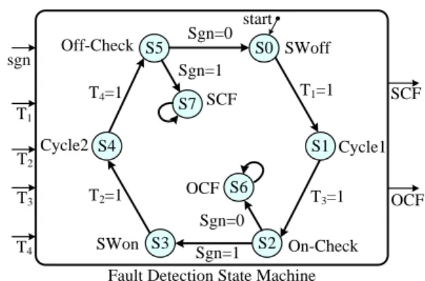
To realize the proposed fault detection method, a State Machine (SM) with five inputs (T1, T2, T3, T4 and the sign of the inductor current slope (sgn signal)), eight states and two outputs (SCF and OCF) is used, as shown in Fig. 5. The PWM switch commands, T1 and T2, are generated by a 15 kHz carrier triangular signal (Fig. 6). According to this Figure, T1 and T2 are corresponding to rising-edges and falling-edges of the switching command (u) respectively. It is clear that by each
pulse of T1, the inductor current iL increases and by T2 this
current decreases. The T3 and T4 signals are activated in the middle of the Cycle1 and Cycle2 respectively. When the carrier signal is equal to zero T3=1 and T4 goes to '1' when the carrier is equal to '1'. Thus, these two signals (T3 and T4) are
independent from the system controller and just depend on the carrier signal.
Besides, this algorithm only needs the sign and not the exact value of the inductor current slope. This one is obtained by
comparing the value of iL(t) with its value at Tsgn=4Ts before,
where Ts stands for the sampling time. When iL increases, sgn=1
and it is equal to '0' when the current decreases.
A. Open Circuit Fault detection
As illustrated in Fig. 5, in initial state (S0), the switch is off, i.e. u=0, and SM stays in this state until u=1 and T1=1; then a transition to state S1 (Cycle1) occurs. In state S1, when T3 goes to '1', a transition to S2 occurs, this state allows to verify the on state of the switch SW. In state S2 (On-Check), the converter is in the middle of Cycle1:
• If no failure has occurred, the switch SW should be on, iL
increases and sgn=1 thus a transition to state S3 occurs.
• If an OCF has occurred, iL decreases and sgn=0. Therefore,
a transition to S6 occurs and SM stays in this state. • In S6, the OCF signal (output of the SM) goes to '1' and an
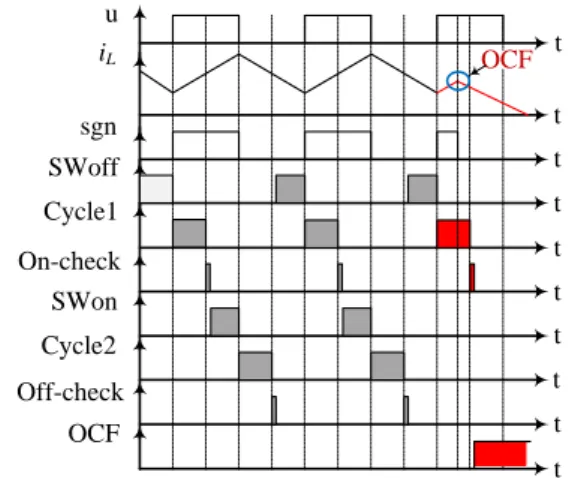
OCF is declared. Fig.7 (a) shows the signals and transitions for OCF detection.
B. Short Circuit Fault detection
For SCF detection, the SM transions from S0 to S2 are the same as in OCF case. In S2 (On-Check), the converter is in the middle of Cycle1, if no failure has occurred (or in a SCF case),
the switch SW is in on state, iL increases and sgn=1 thus a
transition to S3 occurs. State S3 corresponds to the on state of switch SW, SM stays in this state until u=1 and then a transition to S4 occurs when T2=1. According to Fig. 5, S4 coincides with Cycle2. In the middle of Cycle2, signal T4 goes to '1' and then a transition to S5 occurs. In state S5 (Off-Check), the converter is in Cycle2 and the switch SW should be off:
• If no failure has occurred, iL decreases and sgn=0 thus a
transition to S0 occurs.
• If a SCF has occurred, iL increases and sgn=1, thus a
transition to S7 occurs and SM stays in this state.
Fig. 1. Input signals of the State Machine.
Carrier u T1 T2 T3 T4 t t t t t t d sgn iL t t
Fig. 5 The state machine used for FDM.
Off-Check SWoff
T1=1
Fault Detection State Machine T2 Cycle1 T2=1 T1 T4=1 T3=1 sgn SCF start S5 On-Check Sgn=1 SWon Sgn=0 Cycle2 SCF OCF OCF T3 T4 S0 S1 S2 S3 S4 S7 S6 Sgn=1 Sgn=0
Fig.4 Boost converter and operation cycles.
iL u Tsw on off on on off iL SW Vo Vin +
-u L t t + -dTsw Cycle2 Cycle1
• In state S7 the signal SCF goes to '1' and a short circuit fault is declared. Fig. 7 (b) shows the signals and SM transitions for SCF detection.
It should be noted that as a result of non-ideal behavior of power switches, delays and dead times are inevitable.
Furthermore, the needed time (Tdelay) to determine the sign of the
inductor current (sgn) should be considered. Therefore, even in healthy operation of the converter, the sgn signal is delayed with respect to the switching commands. This is why the state (on or off) of the switch SW is verified right in the middle of Cycle1 (S2) and Cycle2 (S5) in order to take into account these delays and dead times.
C. Fault tolerant operation
To ensure service continuity of the PV boost converter after a fault detection and identification, remedial actions are necessary. These actions consist of two parts: fault isolation and system reconfiguration. The proposed FT topology is depicted in Fig.3. According to the type of switch failure (OCF or SCF), different reconfiguration strategies are considered If an OCF occurs, after fault identification by FDM block, the faulty switch can be immediately replaced by the redundant switch SWR (Fig.3). But, in case of SCF, as long as the SCF is present on the switch, SW cannot be replaced by the redundant switch. In fact, in SCF case, after fault detection, first the faulty switch should be isolated by means of fuse protection [24]. After fault detection, identification and isolation, the faulty switch (SW)
will be replaced by the switch SWR. Then, the converter can
operate in normal conditions.
D. fault-tolerant control implementation on a FPGA chip
In this paper, a design methodology based on FPGA (Field Programmable Gate Array) rapid prototyping, so called ''FPGA
in the loop” [24] is used to test experimentally the proposed fault tolerant operation. The proposed FDM and FT strategies are implemented in a FPGA chip, as presented in Fig.3. Before FPGA implementation for HIL experiments, the studied system
has been modeled and successfully simulated in
Matlab/simulink environment, in continuous-time and then discrete-time. Then, the control, FD and FT blocks are translated into a synthesizable VHDL model. Finally, the development board which contains the FPGA can be programmed and used in the HIL simulation. After validation of the fault tolerant method by HIL results, the FPGA can be programmed and the fully experimental tests can be performed. In our case, a Stratix DSP S80 development board is used, which includes the Stratix EP1S80B956C6 FPGA chip. The Fig. 9 shows a synoptic of the HIL.
V. Simulation, HIL and experimental results
A. Energy management simulation results
In this section, simulation results are provided to verify the validity of the proposed energy management approach. The
system is emulated under Matlab-SimPowersSystems
environment.
As it mentioned before, the PV source is controlled by a P&O -MPPT algorithm. The obtained results correspond to the BP 3170 photovoltaic module of the BP solar company. To validate the proposed energy management strategy for the studied microgrid, the DC bus voltage reference is fixed to 200V. The implemented profile of the residential load is focused
on the summer season presented in the first curve (pload) of Fig.
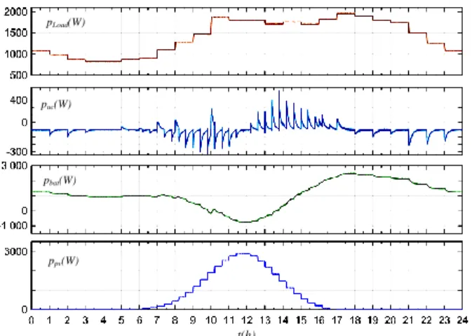
10. This figure presents the hourly average power consumption by the domestic appliances during 24 hours.
DC bus voltage is presented in the top of Fig. 11. It is the same as reference voltage regardless of the load’s variations.
In reality, the daily solar irradiation has the general shape of a curve called ”bell”, which is modeled here by a Gaussian curve. That is why the PV generated power is null from 17h00 to 6h00 in Fig.10. Excepted this period, the PV provides the possible maximum power and supplies the DC bus, as shown in
Fig.11. Corresponding to solar energy variation, the Pmax of PV
has been also varied. As Fig. 10 illustrates, the MPPT algorithm
increases progressively Vpv and converges towards the MPP
voltage to achieve the power peak.
As it mentioned before, the UC is responsible for the rapid load and PV energy variations. It can be seen in Fig. 10, the UC power compensated perfectly the rapid variation either from the load profile or from the PV. This action of the UC allows to have a constant DC bus voltage.
The battery pack which has a slower dynamic compared to the UC, supplies or absorbs the required energy to smooth the difference between the PV produced power and load demand in longer time, as shown in Fig. 10. From 10h00 to 14h00, the PV production is more than the load demand, thus the battery
Fig. 7 OCF detection based on FDM signals. SWoff Cycle1 On-check SWon Cycle2 Off-check OCF u sgn iL t t t t t t t t t t OCF
Fig. 8 SCF detection based on FDM signals. SWoff Cycle1 On-check SWon Cycle2 Off-check SCF u sgn iL t t t t t t t t t t SCF
Fig. 9 Hardware-In-the-Loop (HIL) synoptic.
3- Quartus 2- DSPB 1- Matlab
Implementation
absorbs and stocks energy, that is why the Pbat are negative in this time interval (in Fig. 10). The battery also controls the UC voltage around its nominal voltage (see Fig. 11).
B. Fault Detection Hardware-In-The-Loop Results
For HIL experimentation, the PV Boost converter given in Fig. 1 is considered. Fig. 12 shows detailed HIL results for an open circuit fault detection. At t = 240s an OCF occurs. At this time, the SM is in state S1 corresponding to Cycle1. When T3 goes to ’1’ a transition to S2 occurs, as in normal condition. But,
because of the OCF, the current (iL) decreases (sgn = 0) thus the
SM cannot move to S3 and must generate a transition to the state S6. In this state, the output signal OCF goes to ’1’and the fault is detected successfully at t = 253s. The fault detection time is 13s which is less than one switching period (here Tsw = 67s).
The HIL results for a SCF detection are depicted in Fig. 13. At t = 240s when the SM is in state S1 a SCF occurs. The transitions from S1 to S5 occur normally. In state S5, because of the SCF, the current iL increases and consequently sgn is equal to ’1’, thus a transition to S7 occurs. In S7 the output signal SCF goes to ’1’ and the SCF is detected at t = 287s.The fault detection time in this case is 47s (< 67s). All these results confirm the validity of a very fast fault detection method.
C. Fault tolerant experimental results
Experimental tests are performed, based on the PV boost converter with a redundant switch, as depicted in Fig. 1. To
simulate a switch fault, the upv signal is forced to '0' for an OCF
and '1' for a SCF. The uR is the redundant switch command,
which is equal to zero for pre-fault operation and copies upv for
post-fault operation.
the validity of the FT operation in case of an OCF is verified in Fig.14. In this case, the OCF is detected after 20 µs. According to the proposed reconfiguration strategy, the redundant switch replaces the faulty switch immediately after fault detection and then the system continues to operate in normal conditions.
Fig.15 shows the same results for a SCF. According to these experimental results, the SCF is detected after 42 µs but the current continues to increase until the end of the fuse action. As soon as the faulty switch is removed by the fuse (after 500 µs), the current decreases (sgn=0), the faulty switch is replaced by the redundant switch and then the system continues to operate normally.
VI. CONCLUSION
This paper presents the energy management in a stand alone DC microgrid based on a photovoltaic as a main renewable
Fig. 14 OCF detection and reconfiguration.
Fi. 15 SCF detection and reconfiguration. Tbase 50 µs/div Fault Detection Tbase 200 µs/div Reconfiguration pLoad(W) puc(W) pbat(W) ppv(W) t(h)
Fig. 10 From up to down: power of Load, DC-bus, UC, Battery pack and PV. vdc(V) vuc(V) vbat(V) vpv(V) t(h)
Fig. 11 From up to down: DC-bus, UC, Battery pack and PV voltage.
Fig. 12 Detailed HIL results for OCF detection case.
Fig. 13 HIL results for SCF detection. 5 7 1 1 1 1 1 1 1 1 1 0 30 60 90 120 150 180 210 240 270 300 330 1 7 9 1 1 1 0 30 60 90 120 150 180 210 240 270 300 330 1
energy source with fault tolerant capability. In order to smooth the load and PV production variations an ultra capacitor and a battery pack are used. The UC, due to its rapid dynamic, is responsible to regulate DC bus voltage during fast power variations. The battery pack compensates the difference between PV production and load demanded power in long term. An energy management based on energy balance on DC bus capacitor is proposed in this paper. Proportional-Integral controllers are used in order to control the system and achieve energy management objectives. To guarantee reliability and service continuity a switch fault diagnosis algorithm is applied on the DC-DC converter of the PV source. Performances of the proposed energy management method are validated by simulations The fast fault tolerant operation is implanted on a FPGA chip and some experimental test are performed to verify the validity of the proposed method.
REFERENCES
[1] J. Guerrero, M. Chandorkar, T. Lee, and P. Loh, “Advanced control architectures for intelligent microgrids-part i: Decentralized and hierarchical control,” IEEE Trans. on Ind. Electron., vol. 60, no. 4, pp. 1254–1262, April 2013.
[2] T. Adefarati and R. C. Bansal, "Integration of renewable distributed generators into the distribution system: a review," in IET Renewable Power Generation, vol. 10, no. 7, pp. 873-884, 2016.
[3] I. Ben Salah, B. Bayoudhi, and D. Diallo, “Ev energy management strategy based on a single converter fed by a hybrid battery/supercapacitor power source,” in International Conference on Green Energy, March 2014, pp. 246–250.
[4] D.Wu, F. Tang, T. Dragicevic, J. Vasquez, and J. Guerrero, “Autonomous active power control for islanded ac microgrids with photovoltaic generation and energy storage system,” IEEE Trans. on Energy Convers., vol. 29, no. 4, pp. 882–892, Dec 2014.
[5] E. Serban, M. Ordonez, C. Pondiche, K. Feng, M. Anun and P. Servati, "Power management control strategy in photovoltaic and energy storage for off-grid power systems," IEEE 7th International Symposium on Power Electronics for Distributed Generation Systems (PEDG), pp. 1-8, 2016. [6] K. Rahbar, J. Xu, and R. Zhang, “Real-time energy storage management
for renewable integration in microgrid: An off-line optimization approach,” IEEE Trans. on Smart Grid, vol. 6, no. 1, pp. 124–134, Jan 2015.
[7] S. Dusmez, A. Hasanzadeh, and A. Khaligh, “Comparative analysis of bidirectional three-level dc-dc converter for battery/ultracapacitor automotive applications,” IEEE Trans. on Ind. Electron., vol. PP, no. 99, pp. 1–1, 2014.
[8] Y. Wang, L. Xu, J. Gao and L. Liu, "A new integrated hybrid power supply system for telecom site sharing solution," IEEE International Telecommunications Energy Conference (INTELEC), Osaka, pp. 1-5, 2015.
[9] E. Jamshidpour, B. Nahid-Mobarakeh, P. Poure, S. Pierfederici, F. Meibody-Tabar, and S. Saadate, “Distributed active resonance suppression in hybrid dc power systems under unbalanced load conditions,” IEEE Trans. on Power Electron., vol. 28, no. 4, pp. 1833– 1842, April 2013.
[10] A. Tani, M. Camara, and D. Brayima, “Energy management in the decentralized generation systems based on renewable energy – ultracapacitors and battery to compensate the wind/load power fluctuations,” IEEE Trans. on Ind. Applicat., vol. PP, no. 99, pp. 1–1, 2014.
[11] J. Torreglosa, P. Garcia, L. Fernandez, and F. Jurado, “Predictive control for the energy management of a fuel-cell -battery-supercapacitor tramway,” IEEE Trans. on Ind. Informat., vol. 10, no. 1, pp. 276–285, Feb 2014.
[12] Y. Zhang, D. Meng, M. Zhou and S. Li, "Energy Management of an Electric City Bus with Battery/Ultra-Capacitor HESS," 2016 IEEE Vehicle Power and Propulsion Conference (VPPC), Hangzhou, China, 2016, pp. 1-6.
[13] A. Dizqah, A. Maheri, K. Busawon, and A. Kamjoo, “A multivariable optimal energy management strategy for standalone dc microgrids,” IEEE Trans. on Power Systems, vol. PP, no. 99, pp. 1–10, 2014.
[14] Manganiello, P. and Ricco, M. and Petrone, G. and Monmasson, E. and Spagnuolo, G., “Optimization of Perturbative PV MPPT Methods Through Online System Identification,” IEEE Transactions on Industrial Electronics, vol. 61, no. 12, pp. 6812–6821, Dec 2014.
[15] B. Gu, J. Lai, and J. Dominic, “Hybrid transformer zvs/zcs dc-dc converterwith optimized magnetics and improved power devices utilization for photovoltaic module applications,” IEEE Transactions on Power Electronics, vol. PP, no. 99, pp. 1–1, 2014.
[16] F. Edwin, W. Xiao, and V. Khadkikar, “Dynamic modeling and control of interleaved flyback module-integrated converter for pv power applications,” IEEE Transactions on Industrial Electronics, vol. 61, no. 3, pp. 1377–1388, March 2014.
[17] Chan, F. and Calleja, H., “Reliability estimation of three single-phase topologies in grid-connected PV systems,” IEEE Transactions on Industrial Electronics, vol. 58, no. 7, pp. 2683–2689, July 2011. [18] R. Wu, F. Blaabjerg, H. Wang, M. Liserre, and F. Iannuzzo, “Catastrophic
failure and fault-tolerant design of igbt power electronic converters-an overview,” in 39th Annual Conference of the IEEE Industrial Electronics Society, IECON 2013, 2013, pp. 507–513.
[19] X. Pei, S. Nie, Y. Chen, and Y. Kang, “Open-circuit fault diagnosis and fault-tolerant strategies for full-bridge dc–dc converters,” IEEE Transactions on Power Electronics, vol. 27, no. 5, pp. 2550–2565, 2012. [20] S. Nie, X. Pei, Y. Chen, and Y. Kang, “Fault diagnosis of pwm dc-dc
converters based on magnetic component voltages,” IEEE Transactions on Power Electronics, vol. 29, no. 9, pp. 4978–4988, 2014.
[21] E. Ribeiro, A. Cardoso, and C. Boccaletti, “Fault-tolerant strategy for a photovoltaic dc–dc converter,” IEEE Transactions on Power Electronics, vol. 28, no. 6, pp. 3008–3018, June 2013.
[22] T. Park and T. Kim,, “Novel fault tolerant power conversion system for hybrid electric vehicles,” in IEEE Vehicle Power and Propulsion Conference (VPPC), 2011, pp. 1–6.
[23] M. Shahbazi, E. Jamshidpour, P. Poure, S. Saadate, and M. Zolghadri, “Open-and short-circuit switch fault diagnosis for nonisolated dc–dc converters using field programmable gate array,” IEEE Transactions on Industrial Electronics, vol. 60, no. 9, pp. 4136–4146, 2013.
[24] E. Jamshidpour, P. Poure and S. Saadate, "Photovoltaic Systems Reliability Improvement by Real-Time FPGA-Based Switch Failure Diagnosis and Fault-Tolerant DC–DC Converter," in IEEE Transactions on Industrial Electronics, vol. 62, no. 11, pp. 7247-7255, Nov. 2015 [25] E. Ribeiro, A. . Cardoso, and C. Boccaletti, “Open-circuit fault diagnosis
in interleaved dc–dc converters,” IEEE Transactions on Power Electronics, vol. 29, no. 6, pp. 3091–3102, June 2014.
[26] E. Jamshidpour, S. Saadate and P. Poure, "Energy management and control of a stand-alone photovoltaic/ultra capacitor/battery microgrid," 2015 IEEE Jordan Conference on Applied Electrical Engineering and Computing Technologies (AEECT), , pp. 1-6, Amman, 2015.
[27] H. Yu, R. Lu, T. Wang, and C. Zhu, “Battery ultra-capacitor hybrid energy storage system used in HEV,” Journal of Asian Electric Vehicles, vol. 8, no. 1, pp. 1351–1356, 2010.
[28] J. Jang and J.-Y. Yoo, “Equivalent circuit evaluation method of lithium polymer battery using bode plot and numerical analysis,” IEEE Trans. on Energy Convers., vol. 26, no. 1, pp. 290–298, March 2011.
[29] D. Velasco de la Fuente, C. Rodriguez, G. Garcera, E. Figueres, and R. Gonzalez, “Photovoltaic power system with battery backup with gridconnection and islanded operation capabilities,” IEEE Trans. on Ind. Electron., vol. 60, no. 4, pp. 1571–1581, April 2013.
[30] H. Yin, C. Zhao, M. Li, and C. Ma, “Utility function-based real-time control of a battery ultracapacitor hybrid energy system,” IEEE Trans. on Ind. Informat., vol. 11, no. 1, pp. 220–231, Feb 2015.
[31] C. T. Phan-Tan and N. Nguyen-Quang, "A P&O MPPT method for photovoltaic applications based on binary-searching," 2016 IEEE International Conference on Sustainable Energy Technologies (ICSET), Hanoi, Vietnam, 2016, pp. 78-82.
[32] H. Renaudineau, F. Donatantonio, J. Fontchastagner, G. Petrone, G. Spagnuolo, J.-P. Martin, and S. Pierfederici, “A pso-based global mppt technique for distributed pv power generation,” IEEE Trans. On Ind. Electron., vol. 62, no. 2, pp. 1047–1058, Feb 2015.
[33] J. Raj and A. Jeyakumar, “A novel maximum power point tracking technique for photovoltaic module based on power plane analysis of i-v characteristics,” IEEE Trans. on Ind. Electron., vol. 61, no. 9, pp. 4734– 4745, Sept 2014