Development of a Procedure for the Selection of Candidate Vessels of Opportunity in Support of the Submarine Rescue Diving and Recompression System
by
Robert Andrew Gold B.S. Mechanical Engineering United States Naval Academy, 1999
Submitted to the Department of Ocean Engineering in Partial Fulfillment of Requirements for the Degrees of
Naval Engineer and
Master of Science in Ocean Systems Management at the
Massachusetts Institute of Technology June 2005
C2005 Massachusetts Institute of Technology. All Rights Reserved.
MIT hereby grants to the US Government permission to reproduce and to distribute publicly paper and electronic copies of this the is document in whole r in part.
A I 1A 1n,
Signature of A uthor ... ... .. ... ,...\.... .... .
Department of Ocean Engineering 05 May 2005 ... . . . .
David V. Burke Senior Lecturer, Department of Ocean Engineering Thesis Supervisor Henry S. Marcus Professor of Marine Systems Thesis Supervisor ... . . .. . . . ... . . . .
David S. Herbein essor of the Practice, CAPT, USN
Thesis Reader ...
Michael S. Triantafyllou Professor of Ocean Engineering Chairman, Department of Committee on Graduate Students Certified bv Certified by Certified by Certified by MA SSACHUSETTS INSTifUTE OF TECHNOLOGY
SEP 0
1
2005
... : .W .. . ./ -*1...
.. ..Development of a Procedure for the Selection of Candidate Vessels of Opportunity in Support of the Submarine Rescue Diving and Recompression System
by
Robert Andrew Gold
Submitted to the Department of Ocean Engineering on 05 May 2005 in Partial Fulfillment of Requirements for the Degrees of
Naval Engineer and
Master of Science in Ocean Systems Management ABSTRACT
The U.S. Navy's new system for rescuing stranded submariners, the Submarine Rescue Diving and Recompression System (SRDRS), utilizes a tethered, remotely operated Pressurized Rescue Module (PRM) deployed and controlled from a Vessel of Opportunity (VOO). The PRM is capable of docking with the disabled submarine at pressure and rescuing up to 16 personnel per sortie. The PRM is launched and recovered using a deck mounted A-frame crane called the Launch and Recovery System (LARS). Upon recovery, the PRM docks with the Submarine Decompression System (SDS) to allow transfer and decompression of personnel. The PRM, LARS, SDS, and associated generators and auxiliaries all compose the Submarine Rescue System (SRS). The SRS, approximately 183 tons, is installed aboard the VOO.
The SRS was nominally designed for operation on the U.S. Navy's Auxiliary Fleet Tug, T-ATF, but is actually intended to be a fly-away system, capable of being installed on any available VOO near the disabled submarine. The VOO may be any Offshore Supply Vessel (OSV), Anchor Handling Tug, or offshore barge that has the capacity to handle the SRS and is available in the area of a disabled submarine. Since the SRS must be rapidly deployed, potential VOOs must be quickly identified and evaluated for structural, stability and seakeeping suitability with respect to the requirements for the SRS.
This thesis describes the theoretical background and development of a procedure intended to aid in the analysis and evaluation of potential VOOs for stability and seakeeping suitability. This procedure utilizes limited information about the potential VOO such as length, beam, draft, depth, deck strength, dead weight tonnage, etc. as inputs for rapidly modeling hull geometry. The developed hull geometry is combined with an empirically derived weight distribution which serve as the input for stability analysis for several different load cases and the seakeeping analysis. Theoretical and empirical analyses are used to justify the requisite assumptions and estimates used in developing the VOO stability and seakeeping models. The efficacy of this VOO evaluation process is demonstrated by both a comparison to known stability and seakeeping analyses for the T-ATF, and with a sensitivity analysis of assumed variables. With this process, the U.S. Navy will be able to rapidly analyze and evaluate the stability and seakeeping characteristics of potential Vessels of Opportunity and judge their suitability to carry and deploy the Submarine Rescue System.
Thesis Supervisor: David V. Burke, Jr.
Title: Senior Lecturer, Department of Ocean Engineering Thesis Supervisor: Henry S. Marcus
Title: Professor of Marine Systems Thesis Reader: David S. Herbein
CONTENTS
FIGURES ... 7
TABLES ... 9
ACRON YM S ... 11
Chapter 1. IN TRODU CTION ... 15
1.1. Subm arine Rescue Diving and Recom pression System ... 15
1.2. History and Background of Subm arine Rescue ... 18
1.2.1. Current U S N avy Subm arine Rescue ... 23
1.2.2. International Subm arine Rescue ... 26
1.3. Future U S N avy Subm arine Rescue: SRDRS... 28
1.3.1. M ission N eeds and Operational Requirem ents ... 28
1.4. The Problem of Selecting a Vessel of Opportunity ... 28
1.4.1. V essel of Opportunity Requirem ents ... 29
1.5. Overview of Proposed Methodology for VOO Analysis and Selection... 30
1.6. Thesis Outline ... 31
Chapter 2. THEORETICAL DEVELOPMENT OF A STABILITY AND SEAKEEPING M ODEL ... 33
2.1. Ship Geom etry ... 33
2.1.1. Hull Geom etry and the Developm ent of Hull Offsets ... 34
2.2. Stability... 37
2.2.1. General Hydrostatics and Ship Stability Background ... 37
2.2.2. Application of Stability Criteria... 40
2.3. Seakeeping ... 41
2.3.1. Sea State ... 42
2.3.2. Ship M otions - Theory ... 43
2.3.3. Ship M otions in a Seaway ... 50
2.3.4. A ssessing Ship M otion Response ... 52
Chapter 3. PROCEDURE FOR THE SELECTION OF A POTENTIAL VOO ... 53
3.1. Introduction... 53
3.1.1. Program s Utilized for Selection Procedure... 54
3.1.2. Required Inform ation... 56
3.1.3. Criteria for Adequacy ... 56
3.2. D eck Geom etry V erification... 56
3.3. Hull Offset Generation... 57
3.4. D evelopm ent of PO SSE Ship M odel... 57
3.5. Stability Analysis in POSSE... 58
3.6. Seakeeping Analysis in POSSE SM P ... 59
3.7. V OO A dequacy Analysis Procedure Conclusion ... 61
Chapter 4. VERIFICATION OF VOO SELECTION PROCEDURE... 63
4.1. Introduction... 63
4.2. Comparison of VOO Selection Procedure Results for the T-ATF versus Known Results 63 4.2.1. Hull Generation... 64
4.2.2. Stability... 65
4.3. Sensitivity Analysis of Assumptions ... 70
4.3.1. Stability Sensitivity Analysis ... 72
4.3.2. Seakeeping Sensitivity Analysis ... 73
4.3.3. Sensitivity Analysis Conclusion... 77
4.4. Results and Observations for Other Potential VOOs: OSV, AHTs and Barges ... 77
4.4.1. Anchor Handling Tug Example Analysis ... 77
4.4.2. Ocean Going Barge Example Analysis... 79
4 .5 . C on clu sion ... 82
Chapter 5. ANALYSIS OF OPTIONS FOR IMPLEMENTATION OF VOO SELECTION... 83
5.1. VOO Selection in Practice ... 83
5.2. VOO Selection Process ... 83
5.3. VOO Selection Process Improvement Options ... 85
5.3.1. Establish Pre-qualified VOO database... 85
5.3.2. VOO Classing ... 86
5.3.3. Design and build to SRDRS requirements... 87
5 .4 . C on clu sio n ... 8 8 Chapter 6. CONCLUSIONS AND FUTURE W ORK ... 89
6 .1. V O O S election ... 89
6.2. Future W ork and Refinements ... 89
6 .3 . C on clu sion ... 9 0 W O R K S C IT E D ... 9 1 APPENDIX A. VOO SELECTION PROCEDURE... 95
APPENDIX B. COM PARISON ANALYSIS RESULTS ... 125
APPENDIX C. SENSITIVITY ANALYSIS RESULTS ... 129
FIGURES
Figure 1.1. A U W S (N A V SEA 2004, 7) ... 15
Figure 1.2. SD S, SR S and PR M ... 15
Figure 1.3. Pressurized Rescue Module (NAVSEA 2004, 72)... 16
Figure 1.4. Transfer of Personnel to the SDS (NAVSEA 2004, 64) ... 17
Figure 1.5. left Cdr. McCann, center Secretary of the Navy Edison, right Cdr. Momsen (US N av y 19 3 9 )... 19
Figure 1.6. McCann Rescue Chamber Interior View (Dunmore 2002, 81)... 20
Figure 1.7. McCann Rescue Chamber Initial Testing (Dunmore 2002, 80)... 20
Figure 1.8. McCann Rescue Chamber At-Sea Testing (Dunmore 2002, 80) ... 21
Figure 1.9. Squalus Rescue in Progress (Dunmore 2002, 82) ... 22
Figure 1.10. Current Submarine Rescue Chamber (US Navy 2000)... 24
Figure 1.11. D SR V A irlift ... ... 24
Figure 1.12. Subm arine D SRV Transport... 25
Figure 1.13. D SR V Inner H ull... 25
Figure 1.14. Possible NATO Submarine Rescue System (Royal Navy, UK 2005) ... 26
Figure 1.15. ASRV REMORA (RAN 2004) ... 27
Figure 1.16. REMORA Deployed with LARS (NAVSEA 2004, 20)... 27
Figure 1.17. Example of OPL-AHTS Database... 29
Figure 1.18. VOO Selection Procedure Overview... 31
Figure 2.1. B asic H ull Characteristics ... 34
Figure 2.2. Ship Metacenter (SNAME 1988, 1: 71) ... 38
Figure 2.3. Longitudinal M etacenter... 39
Figure 2.4 Normalized Bretschneider Spectrum (SNAME 1989, 3: 37)... 43
Figure 2.5. Sign conventions for ship motions (Faltinsen 1990, 41)... 44
Figure 2.6. (SN A M E 1989, 3: 47) ... 45
Figure 2.7. (SN A M E 1989, 3: 47) ... 45
Figure 2.8. Graphic Representation of Strip Theory (SNAME 1989, 3: 52)... 48
Figure 2.9. Graphic Representation of Strip Theory (Faltinsen 1990, 50) ... 49
Figure 3.1. V O O Selection Procedure ... 53
Figure 3.2. Example of AHTS Query filtered for potential VOOs... 54
Figure 3.3. ASSET Hull Isometric View ... 57
Figure 3.4. Lightship W eight D istributed ... 58
Figure 3.5. SMP Postprocessor Response Output ... 60
Figure 4.1. Comparison Analysis; T-ATF Hull Isometric View ... 64
Figure 4.2. Initial G M t vs V C G ... 72
Figure 4.3. M ax G Z vs V C G ... 73
Figure 4.4. Max Vertical Acceleration vs VCG... 74
Figure 4.5. Max Vertical Acceleration vs LCG... 75
Figure 4.6. Max Transverse Acceleration vs VCG... 76
Figure 4.7. Max Transverse Acceleration vs LCG ... 76
Figure 4.8. Random Selection of a Potential VOO... 78
Figure 5.1. VOO Operational Selection Process (NAVSEA 2004, 3)... 84
Figure A. 1. ASSET Editor ... 99
Figure A.2. ASSET Body Plan Output ... 101
Figure A.3. ASSET Hull Isometric View ... 102
Figure A.4. ".scp" Offsets File... 104
Figure A.5. "*.off" M odified File ... 105
Figure A.6. Entry of New Ship Project Particulars... 106
Figure A.7. Verification of Imported Hull Geometry... 107
Figure A.8. POSSE 4 W orkspace ... 108
Figure A.9. Intact and Trim Stability Summary for Lightship Weight Derivation... 109
Figure A. 10. Tankage and Cargo Entry for Lightship W eight Derivation... 109
Figure A.11. Lightship W eight Entry ... I11 Figure A. 12. Lightship W eight Distribution Generation... 112
Figure A.13. Lightship W eight Distributed ... 112
Figure A. 14. POSSE W orkspace ... 114
Figure A. 15. Righting Arm Summary Viewpane ... 116
Figure A.16. Lightship Load Case Righting Arm... 119
Figure A. 17. Intermediate Load Case Righting Arm... 119
Figure A. 18. Full Load Case Righting Arm ... 119
Figure A.19. M odified Full Load Case Righting Arm... 120
Figure A.20. M otion at a Point Entry ... 122
TABLES
Table 1.1. Summary of SRC and DSRV Capabilities (US Navy, DSU n.d.) ... 23
Table 1.2. Criteria for V O O A dequacy... 30
Table 2.1. B asic H ull Characteristics... 34
Table 2.2. Coefficients of Form (SNAME 1988, 1: 18-19) ... 35
Table 2.3. Linearized Equations of Motion (SNAME 1989, 3: 46)... 45
Table 2.4. Summary of Statistical Response Maxima (SNAME 1998, 3: 91) ... 52
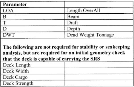
Table 3.1. Parameters Required for VOO Analysis... 56
Table 3.2. Recom m ended Load Plans ... 59
Table 4.1. Comparison Analysis T-ATF Vessel Information... 63
Table 4.2. H ull G eneration D ata ... 64
Table 4.3. Comparison Analysis; Asset Hull Geometry Summary ... 65
Table 4.4. Comparison Analysis; Departure LARS vert ... 66
Table 4.5. Comparison Analysis; Mid-Voyage LARS vert... 67
Table 4.6. Comparison Analysis; Return LARS vert ... 67
Table 4.7. Comparison Analysis; Seakeeping Models ... 68
Table 4.8. Comparison Analysis; Ship Motion Seakeeping Results at CG... 69
Table 4.9. Comparison Analysis; Seakeeping Results at Head of LARS with ROV Over Water ... 70
Table 4.10. Sensitivity Analysis Input Variable Ranges ... 70
Table 4.11. JM P R un Pattern ... 71
Table 4.12. Neftegaz-5 1, Anchor Handling Tug Characteristics... 78
Table 4.13. Worst Case Stability Loading Case: Return with LARS Vertical... 79
Table 4.14. Ocean Going Barge Characteristics... 80
Table 4.15. Ocean Going Barge Hull Generation Data ... 80
Table 4.16. Barge Worst Case Stability Loading Case with LARS Vertical ... 82
Table 5.1. Summary of Rescue System Required Physical Characteristics (NATO 2004,... 87
Table A. 1. Parameters Required for VOO Analysis ... 96
Table A .2. Criteria for V O O A dequacy ... 97
Table A .3. D eck G eom etry Criteria ... 98
Table A .4. D ata for A SSET Hull Generation... 100
Table A .5. A sset Printed R eport ... 103
T able A .6. Stability C riteria ... 115
Table A.7. Recommended Alternative Load Plans... 118
ACRONYMS
AHT Anchor Handling Tug AP After Perpendicular
ASRV Australian Submarine Rescue Vehicle
ASSET Advanced Surface Ship Evaluation Tool
AUWS Advanced Underwater Work System
B Beam
BL Baseline
CL Center Line
COTS Commercial Off The Shelf
D Depth
DISSUB DISabled SUBmarine
DSRV Deep Submergence Rescue Vehicle DTL Deck Transfer Lock
DWT Dead Weight Tonnage FP Forward Perpendicular
IMO International Maritime Organization
ISO International Organization for Standardization LARS Launch And Recovery System
LBP Length Between Perpendiculars
LOA Length Over-All
LWL Length on Water Line
MOSUB Mother Submarine
MOSHIP Mother Ship
MS Midships, also indicated by the symbol:
NAVSEA Naval Sea Systems Command
OPL Oilfield Publications, Ltd.
OSV Offshore Supply Vessel
POSSE Program of Ship Salvage and Engineering
PRM Pressurized Rescue Module
RAO Response Amplitude Operator
ROV Remotely Operated Vehicle
SDS Submarine Decompression System
SMP Ship Motions Program
SRC Submarine Rescue Chamber
SRDRS Submarine Rescue Diving and Recompression System
SRS Submarine Rescue System
T Draft
TUP Transfer Under Pressure
VAA VOO Adequacy Analysis Procedure
VOO Vessel Of Opportunity
WL Water Line
Acknowledgments
The author would like to thank the following individuals for their help and support: Professor Chryssostomos Chryssostomidis, Mr. John O'Donnel, Commander William Brougham, Commander Christopher Warren, Captain David Herbein, Professor Henry Marcus, Dr. David Burke, and Amelia.
Chapter 1. INTRODUCTION
1.1. Submarine Rescue Diving and Recompression System
The Submarine Rescue Diving and Recompression System (SRDRS) is a transportable, modular submarine rescue system that will be capable of rapid deployment anywhere in the world for operations from a Vessel Of Opportunity (VOO) instead of a dedicated mother-ship. The SRDRS consists of two separate systems, shown in Figure 1.1 and Figure 1.2: the Advanced Underwater Work System (AUWS), and the Submarine Rescue System (SRS). The SRS is further divided into the Pressurized Rescue Module (PRM) and its associated support equipment, and the Submarine Decompression System (SDS).
SRS and
SDS
PRM
Figure 1.1. AUWS (NAVSEA 2004,7) Figure 1.2. SDS, SRS and PRM (NAVSEA 2004, 36)
All SRDRS systems are packaged with standard ISO (International Organization for
standard 40 ft trailer chassis. All this enables the SRDRS components to be transported with commercial carriers.
Upon receiving notice of a Disabled Submarine (DISSUB), the SRDRS components will depart from their storage warehouse in San Diego, California, travel by truck and airplane to the airport nearest the location of the selected VOO. The SRDRS will then be trucked to the seaport where the VOO is located. The AUWS will depart on its own dedicated VOO and transit to the location of the disabled submarine. Once on scene, the AUWS will assess the general situation, prepare the area and clear the submarine's hatch. After the SRS is installed on its VOO, it will transit to the location of tlr disabled submarine and begin rescue operations. The PRM
(Figure 1.3) is a Remotely Operated Vessel (ROV) controlled from a console on the VOO and deployed using the Launch and Recovery (LARS) A-frame.
Figure 1.3. Pressurized Rescue Module (NAVSEA 2004, 72)
After launch, the PRM is driven down to the disabled submarine where tle PRM's transfer skirt attaches under pressure to the submarine's hatch. Two attendants onboard the PRM then aid in transferring disabled submarine crew members to the PRM. Once the PRM is full (16
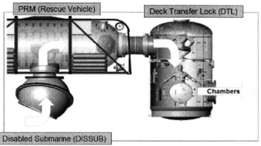
submariners and 2 attendants) and the disabled submarine's hatch is secured, the PRM returns to the VOO. The PRM is recovered via the LARS and attached to the Deck Transfer Lock (DTL) (Figure 1.4). The DTL is directly attached to the SDS, enabling the transfer of the rescued submariners at pressure.
Figure 1.4. Transfer of Personnel to the SDS (NAVSEA 2004, 64)
The SDS consists of two hyperbaric chambers which can decompress 31 people in each for a total of 155 people over multiple PRM sorties. Once in the SDS, submariners are decompressed and treated for other casualties they may have.
The rapid deployment scheme of the SRDRS requires every event in the sequence of moving the system from its warehouse to the site of the disabled submarine be planned in advance, before any submarine disaster occurs. Since transportation modes are standardized, loading for trucks and airlift can be readily planned. VOO selection, on the other hand, is the one element in this chain that escapes easy planning. Although the VOO could potentially be any kind of Offshore Supply Vessel (OSV), Anchor Handling Tug (AHT), offshore barge, or similar vessel, the sheer number of different vessels which could potentially be used precludes making any kind of generalizations on ship type that might reflect adequacy for a vessel to be a VOO. Instead, the contractor coordinating the SRDRS deployment may only know limited information about the vessels which are in the area of a disabled submarine. Selection of the
VOO must be based on that limited knowledge, which is most likely only basic characteristics such as length, beam, draft, Dead Weight Tonnage (DWT), etc.
1.2. History and Background of Submarine Rescue
One person more than any other is responsible for the establishment and development of submarine rescue: Vice Admiral Charles "Swede" Momsen, USN. On September 25, 1925, Lieutenant Commander Momsen had command of his first submarine, the S-1, and was
dispatched to aid in the search for the submarine S-51 which had been lost after being struck by a merchant ship. Momsen located an oil slick marking the general area where S-51 was lost but was unable to pinpoint the sub or effect any sort of rescue (ONR n.d.). When S-51 was
recovered, Lieutenant Commander Momsen discovered that three (one of whom was a close friend of Momsen's) of the 36 officers and crew of S-51 had survived the collision only to die during their hopeless struggle to escape (USS Momsen n.d.). Shortly after the S-51 accident, the S-4 sank off Cape Cod. This time six submariners survived for three days in the torpedo room (ONR n.d.). The S-4 incident further reinforced Momsen's resolve to take corrective actions as he later described in a 1939 lecture to the Harvard Engineering Society:
Eleven years ago [1928] the first diving bells for rescuing men from submarines were designed by the Bureau of Construction and Repair, Navy Department. A curious quirk of circumstances led up to this incident. While in command of the submarine S-1 [SS-1 05], in 1926, I wrote to the Bureau of Construction and Repair and recommended the adoption of a diving bell for the purposes of rescuing entrapped personnel from submarines. The S-1 carried the only
submarine airplane hanger in the Navy and I completed tests with a new type of plane during my tours of duty. This hanger was a tank 20 feet long and 6
feet
indiameter. When I was relieved of command of the S-1, I went to the Navy Department, Bureau of Construction and Repair, for duty in the Submarine section. There Ifound my letter about the diving bell, unanswered. A short time later I handled a letter from the new commanding officer of the S-1, stating that the airplane tank was of no further use, requesting authority to remove it, and requesting disposition. Ifelt opportunity knocking and prepared a reply to send it to New York there to be cut in half and used to make two diving bells for
experimental purposes. (Momsen 1939)
Momsen's efforts in developing the rescue chamber and the "Momsen Lung" submarine rescue breathing device, first at the Bureau of Ships and then at the Submarine Safety Test Unit
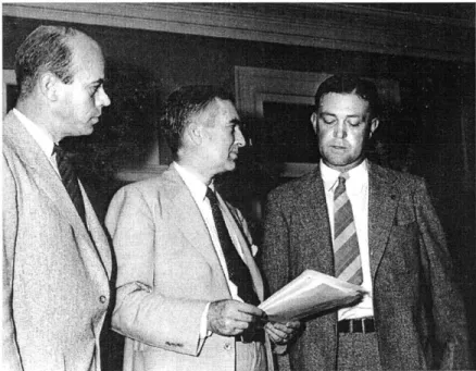
and Experimental Dive Unit, formed the genesis of the Navy's submarine rescue capability. The initial rescue chamber design developed by Momsen was further refined by his relief at the Experimental Diving Unit, Commander Allan McCann (both shown with the Secretary of the Navy in Figure 1.5).
Figure 1.5. left Cdr. McCann, center Secretary of the Navy Edison, right Cdr. Momsen (US Navy 1939)
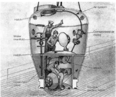
The final rescue chamber design (Figure 1.6 and Figure 1.7) was finished in 1930 and dubbed the "McCann Rescue Chamber." It consisted of a two chamber diving bell with ballast tanks and a rubber skirt that would aid in creating a seal when the chamber mates with the escape hatch of a disabled submarine. The upper chamber housed two operators and up to seven rescued
submariners. The lower chamber would be isolated from the upper chamber while mating to the escape hatch in high pressure.
Figure 1.6. McCann Rescue Chamber Interior View (Dunmore 2002, 81)
Figure 1.7. McCann Rescue Chamber Initial Testing (Dunmore 2002, 80)
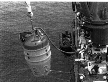
As shown in Figure 1.8, The McCann Rescue Chamber was deployed from an auxiliary ship using winches and cranes controlling a cable attached to the top of the chamber. When
attach a downhaul wire. The wire would then serve to guide the rescue chamber directly to the escape hatch. After being hoisted into the water, the rescue chamber would fill its ballast tanks and dive to the escape hatch, traveling along the guide wire. Once the rescue chamber was in place and bolted to the escape hatch, the lower chamber air pressure would be reduced to create a tight seal and facilitate the transfer of personnel.
Figure 1.8. McCann Rescue Chamber At-Sea Testing (Dunmore 2002, 80)
Momsen's (and McCann's) tenacity in establishing submarine rescue capability was soon to pay off. On May 23, 1939, the USS Squalus (SS 192) departed its homeport of Portsmouth, New Hampshire, on acceptance trials. While on its nineteenth test dive, flooding in the after engine room was reported. The diving officer immediately blew forward and emergency ballast tanks. Squalus momentarily leveled but then rapidly sank by the stem coming to rest on the seafloor, 243 feet below the surface. Contrary to indicator lights, a main induction valve for diesel engine air had somehow opened causing the rapid flooding of the aft compartments and immediate drowning of 26 men in those compartments. In the forward compartments, where air pressure had rapidly increased due to the flooding, commanding officer Lieutenant Oliver F. Naquin ordered the distribution of Momsen Lungs but decided to delay escape and wait for rescue since their depth was beyond what was deemed safe. (Dunmore 2002, 74-84; Maas
1999; US Navy 1939; US Navy 2000; )
Five hours after the Squalus sank, its sister ship, USS Sculpin began searching at the Squalus' reported position prior to diving. Due to an error ashore in recording that position, Sculpin was searching five miles from Squalus' actual position. Finally, Ensign Ned Denby on
the bridge of Sculpin spotted flares from Squalus. Sculpin arrived on scene and was able to momentarily establish sound-powered phone contact with Squalus before a large wave caused the line to snap. Squalus sat on the bottom, with 33 men in cold dark silence. (Dunmore 2002,
77)
Twenty-three hours after Squalus went down, USS Falcon arrived on scene carrying the McCann rescue chamber. Also arriving was Lieutenant Commander Momsen, sent to supervise the rescue. Divers quickly found Squalus and attached the downhaul wire to the escape hatch. Momsen decided it was too dangerous to risk five sorties that would be required if each trip was
limited to rescuing seven people. Instead, the first sortie returned seven people, the second and third nine people (Figure 1.9).
Figure 1.9. Squalus Rescue in Progress (Dunmore 2002, 82)
The fourth and final sortie brought the remaining eight submariners aboard the rescue chamber, including Lieutenant Naquin. As the chamber ascended, the sheave hauling in the chamber's wire rope jammed and the wire rope began to part. In order to prevent the loss of the chamber, it was lowered to the sea floor. Divers were sent down to attach a second hoist cable. After two attempts failed with the divers succumbing to the extreme depth (and being brought back to the surface for decompression treatment), Momsen decided to recover without cables - using only ballast control. After four and a half hours on the bottom, the rescue chamber rose towards the
surface; guided by what remained of the wire rope being hauled in manually by ten men. (Momsen 1939; Dunmore 2002, 83)
Although 26 men perished on Squalus, 33 men were saved. Momsen remained on the scene of the disaster to supervise the salvage and recovery of Squalus. With the arrival of the McCann rescue chamber, the U.S. Navy had a proven means of rescuing submariners.
1.2.1. Current US Navy Submarine Rescue
The U.S. Navy's current submarine rescue capability is provided by three SRCs and one Deep Submergence Rescue Vehicle (DSRV), Mystic (Figure 1.11). The second DSRV, Avalon, was decommissioned in 2000. The capabilities of the SRC and DSRV are summarized in Table
1.1. Table 1.1. Summary Weight Displacement Crew Rescuee Capacity Max Depth Speed
of SRC and DSRV Capabilities (US Navy, DS U n.d.)
SRC 21 DSRV 1 21,600 lbs 76,000 lbs 21,550 lbs 82,000 lbs 2 4 6 24 850 ft 5,000 ft
NA 4.1 Knots/8 Hours (Max)
2.5 Knots/14 Hours (Transit) 1.5 Knots/18 Hours (Search)
The SRC (Figure 1.10) operates from a mother vessel in conjunction with the supporting cables, umbilical, air compressors, air banks, control consol, mooring and rigging van,
Submarine Rescue Cable Reel, SRC fly away stand and other assorted support equipment. The SRC mode of operation is identical to the original McCann Rescue Chamber.
Figure 1.10. Current Submarine Rescue Chamber (US Navy 2000)
DSRV 1 began service in 1971 and is intended "to provide a quick reaction, worldwide, all-weather capability to rescue personnel from disabled submarines at depths up to 2,000 ft."
(US Navy, DSU n.d.) DSRV is deployed via a C-5 aircraft from its homeport in San Diego,
California (Figure 1.11).
Figure 1.11. DSRV Airlift
After being flown by an Air Force C-5 to the nearest capable port, the DSRV is loaded on a waiting mother submarine for transport to the disabled submarine, shown in Figure 1.12. Once the DSRV is in the vicinity of the disabled submarine, the DSRV pinpoints the location of the disabled submarine with its onboard sonars.
Figure 1.12. Submarine DSRV Transport
The DSRV mates to the disabled submarine using a skirt and hold-down mechanisms similar to the SRC's. Once the connection is secure, the pressure inside the skirt is equalized with the pressure inside the disabled subrmarine and the hatches are opened. After any rescue supplies are transferred to the disabled submarine (CO2 scrubbers, food, water, etc.) up to 24 rescuees are
transferred to the DSRV, hatches are closed in reverse order, and the DSRV returns to its mother sub. The outer-hull of the DSRV is spun fiberglass, the inner- hull is three connected HY- 140 steel spheres, shown in Figure 1.13. Operators are located in the forward most sphere, rescuees and attendants are located in the aft two spheres which can be pressurized as necessary.
(GlobalSecurity.org 2002; US Navy, DSU n.d.)
Although the DSRVs have performed their mission well, the fact that they have to operate from a mother sub or specially adapted surface ship greatly limits how they can be deployed in the event of an actual disabled submarine. Additionally, without a true hyperbaric chamber, they lack the ability to treat and decompress rescuees. To make up for these
deficiencies, in 1992 the U.S. Navy issued a Mission Needs Statement stating the requirements for a new submarine rescue system. (NAVSEA 2004, 4)
1.2.2. International Submarine Rescue
Several countries have submarine rescue capability, but many have the same limitations as the DSRV or lack the capacity that would be required for a U.S. system. There is also a
NATO Submarine Rescue System, shown in Figure 1.14, in development with many of the same
requirements of the SRDRS. Above any others, though, the Australian Navy's REMORA Submarine Rescue Vehicle offers the best glimpse of an operational system that most closely meets the needs of a U.S. system.
Figure 1.14. Possible NATO Submarine Rescue System (Royal Navy, UK 2005)
Royal Australian Navy REMORA
The Australian Submarine Rescue Vehicle (ASRV) REMORA, shown in Figure 1.15, is a remotely operated vehicle built around a diving bell capable of rescuing up to six people (with one attendant). It is equipped with a trainable mating skirt that can mate with hatches up to 60 deg
from vertical. The REMORA is deployed using a LARS A-Frame (Figure 1.16). It is operated and supported by vans located onboard the mother ship. The support equipment includes two decompression chambers capable of the Transfer Under Pressure (TUP) of personnel under pressure and treating up to 36 people each. The whole system can be packaged in ISO
containers, shipped (anywhere in Australia) and installed on a mother ship, "ready to sail," within 72 hours (RAN 2004). Since the ASRV REMORA has been in operation for seven years including use in exercises, it provides a good model for the evertual use and operation of the SRDRS.
Figure 1.15. ASRV REMORA (RAN 2004)
1.3. Future US Navy Submarine Rescue: SRDRS
1.3.1. Mission Needs and Operational RequirementsAs discussed earlier, the existing SRC and DSRV systems do not have the capability for rapid deployment or treatment of large number of casualties. This shortfall prompted the development of a Mission Needs Statement (MNS) and subsequent Operational Requirements Document (ORD). As summarized in the NAVSEA SRDRS system brief, the general mission requirements include:
* Worldwide rapid response, not constrained by requirement for dedicated support vessels nor Mother Submarines (MOSUBs)
e Operate
from
VOOs* Perform end-to-end rescue of crew from pressurized disabled submarine
* Government Owned/Contractor Operated (GO/CO) maintenance and operations
to
facilitate
crew training & proficiency* Maximize use of COTS [Commercial Off The Shell] technologies and open software/processor architectures to simplify procurement of spares and the incorporation offuture upgrades
* System is modular ... shipping packages optimized for either commercial or military transport (NAVSEA 2004, 11)
These mission requirements, specific system configuration requirements, and the decision to use the T-ATF as the baseline VOO provided the framework which guided the initial SRDRS
designs. With the SRDRS nearing the end of design and construction one critical issue remained: how to select a Vessel of Opportunity.
1.4. The Problem of Selecting a Vessel of Opportunity
In addition to the operational requirements, the SRDRS was designed to a set of
engineering standards (US Navy and commercial) all within the constraint of using the T-ATF as a VOO. Because the T-ATF is unlikely to be used as a VOO in an actual rescue, the constraints defined by the T-ATF case serve as a set of minimum requirements for the VOO. Even given that set of VOO requirements, the problem of selecting a VOO from a world of wssels still exists. Potential VOOs can be located and identified by shipping brokers, often the only information that is known about the potential VOOs are the basic vessel characteristics that are part of vessel registers and databases such as the Oilfield Publications, Ltd. Anchor Handling
Tugs and Supply Vessels (OPL-AHTS) database. An example of the data available in this database is shown in Figure 1.17.
. . . ... . . . .
-Wft~Ummfi Tti, TOE -Wt-nHm'Ei ET NCKA~ott JW T n T
S 737 713 A A HP4rt/I oasiy# , 6S 185 11 ! 2 1 1O6-1497 10C0 G 4 , 194 19i3
4 AH unFrjuz 2' 1 9 2N9 - 14 11W 11 S 1 tAHVa4z 992 13 E1V z 4 ~ 44 4 - 4 AsfMon 43 141 3 4 4 317 - ai an 41 1A 1 41Z 129 430 Abd Cr4m 44 11 M 1 2 1 449 9 X d93 91 319 31 4 3439, 3H. 79 119 7i9 94 ., Ii W I C7 7 ,,,*. .. .
Figure 1.17. Example of OPL-AHTS Database
Given those basic characteristics, vessels which have been identified as potential V00s must be quickly evaluated for their adequacy to carry the SRDRS. In order to do that, this thesis will use commercially available computer programs to develop hull geometry based on those
characteristics, estimate vessel weight and weight distribution and finally analyze the stability
and seakeeping adequacy of the vessel for supporting the SRS. A separate study is examining
the issue of
judging
structural adequacy with respect to detailed scantling information.1.4.1. Vessel of Opportunity Requirements
The specific requirements which will be used to
judge
the adequacy of a potential VOO to support the SRS are listed in Table 1.2. The deck geometry requirements are based on explicitrequirements from documents in NAVSEA 0OC31 SRS System Documents, Vessel of
Opportunity Documents, Volume 9. The stability requirement uses the "IMo Resolution
A.749(18)-3.1 (A.167), General Intact Stability Criteria for All Ships", but other stabil ityeria can be used if desired. The seakeeping acceleration requirements are based on the John J. McMullen Associates (JJMA) T-ATF seakeeping analysis (JJMA 1996) which provided the basis for the constraints used in the design of the SRDRS.
Table 1.2. Criteria for VOO Adequacy
Parameter Value
DECK GEOMETRY(NAVSEA 1, 2, 11)
Deck Length (min) 29.3 m (96 ft)
Deck Width (min) 9.14 m (30 ft)
Deck Cargo (min) 185.5 tonnes (182.6 LT)
Deck Strength (min) 2 tonnes/m (0.19 LT/ft2= 2.8 psi) STABILITY
(IMO Resolution A.749(18)-3.1 (A.167), General Intact Stability Criteria for All Ships)
GZ vs Angle of Heel:
Area to 30 deg (min) 0.05 m-rad (9.4 ft-deg)
Area to 40 deg (min) 0.09 m-rad (16.92 ft-deg)
Area 30 to 40 deg (min) 0.03 m-rad (5.64 ft-deg)
Angle at Max GZ (min) 25 deg
Max GZ 0.2 m (0.66 ft)
Initial GM (min) 0.15 m (0.49 ft)
SEAKEEPING, up to Sea State 4, accelerations at head of LARS A-Frame at max aft outreach. (John J. McMullen Associates, 7, 8)
Longitudinal Acceleration 0.20 g Transverse Acceleration 0.39 g
Vertical Acceleration 0.31 g
1.5. Overview of Proposed Methodology for VOO Analysis and Selection
In order to perform stability and seakeeping analyses using the limited information contained in the OPL-AHTS database, assumptions and estimations will necessarily have to be made regarding the actual properties of the potential VOOs. Some of these estimations will directly influence the development of the hull geometry, weight location and distribution. These assumptions are necessary to perform the required stability and seakeeping analyses. This thesis will attempt to show that the underlying assumptions used in developing the VOO characteristics are based on basic naval architectural principles or typical vessel characteristics. The proposed analysis procedure, summarized in Figure 1.18, begins by verifying the basic deck geometry for the required area to hold the SRS. Next, the hull geometry is generated and used to create a model of the ship including the lightship weight distribution. The ship model is then used as the
starting point for tle stability analysis which evaluates the potential VOO against stability criteria at a number of different loading conditions, all with the SRS loading included. Finally, the seakeeping analysis is performed using the ship model that was previously developed.
Basic Geometry Check
Ship Model Creation
(Hull Geometry and Lightship Weight Distribution)
Stability Analysis
Seakeeping Analysis
Figure 1.18. VOO Selection Procedure Overview
1.6. Thesis Outline
"
Chapter 2. THEORETICAL DEVELOPMENT OF A STABILITY AND SEAKEEPINGMODEL - Develops the theoretical and analytical underpinnings of the VOO stability
and seakeeping analysis procedure.
* Chapter 3. PROCEDURE FOR THE SELECTION OF A POTENTIAL VOO
-Describes the VOO analysis procedure using illustrations and examples from the procedure tutorial of APPENDIX A
" Chapter 4. VERIFICATION OF VOO SELECTION - Compares the results of using the T-ATF in the analysis procedure against the known stability of the T-ATF and two different methods of seakeeping analyses performed on the T-ATF. This chapter also describes a sensitivity analysis performed with the estimated hull coefficients using the T-ATF characteristics and the results of the procedure applied to a larger AHT and deck barge.
" Chapter 5. ANALYSIS OF OPTIONS FOR IMPLEMENTATION OF VOO SELECTION - examines other options for selecting adequate VOOs.
" Chapter 6. CONCLUSIONS AND FUTURE WORK - final observations suggestions for future work and areas of study, and final conclusions
Chapter 2. THEORETICAL DEVELOPMENT OF A
STABILITY AND SEAKEEPING MODEL
Since the whole deployment process of the SRDRS must happen quickly, potential VOOs must be rapidly identified and evaluated for suitability. This thesis is concerned with the
process of evaluating the stability and seakeeping of potential VOOs. Although empirical models exist for analyzing the stability and seakeeping performance of ships, modern computer programs which can perform a full, physics based analysis are both readily available and can
quickly analyze a vessel. These analysis programs, and the programs which I will use for this thesis require accurate hull geometry and weight distribution. Unfortunately, the vessel information that may be available for analysis is likely limited to gross hull and weight
characteristics. As with many aspects of this analysis procedure, limited vessel information will lead to an adequate model that can be analyzed only by making key assumptions about hull geometry and weight distributions. This chapter will discuss those assumptions within the context of developing the theory underlying the stability and seakeeping analyses.
2.1. Ship Geometry
As discussed above, developing a vessel's basic hull geometry is the first step in being able to perform stability and seakeeping analyses. Since the process this thesis proposes will develop hull eometry from limited basic information, only primary hull geometry will be developed and hull appendages ignored. I expect that any differences in hull geometry or appendages between the model and actual vessel will have a small impact on either the stability or seakeeping analysis. I will examine and verify this hypothesis in Chapter 4.
2.1.1. Hull Geometry and the Development of Hull Offsets
The basic hull characteristics that will be used are illustrated in Figure 2.1 and defined in Table 2.1. MS AP B FP CL LOA LBP LWL '.4 WL
Figure 2.1. Basic Hull Characteristics
Table 2.1. Basic Hull Characteristics
AP After Perpendicular B Beam BL Baseline CL Center Line D Depth FP Forward Perpendicular
LBP Length Between Perpendiculars
LOA Length Over-All
LWL Length on Water Line
MS Midships, also indicated by the symbol:
T Draft
WL Water Line
-4
D
The following equations (Table 2.2) define the basic coefficients used to describe a hull where ? is the displacement of a vessel at a given draft and V is the volume of displaced water at a given draft:
Table 2.2. Coefficients of Form (SNAME 1988, 1: 18-19)
Block Coefficient, CB
Midship Coefficient, CM where Am = immersed area of the midships section
Prismatic Coefficient, Cp
Waterplane Coefficient, Cwp
Where A wp = waterplane area
V CB = L-B.T - Tm L-B -T -Cm CWP - T Equation 2.1 Equation 2.2 CB Equation 2.3 CM Equation 2.4
The procedure of developing the geometry of the VOO's hull is not unlike the design process for a new hull. The goal is to develop the overall hull geometry from limited
information. The hull geometry is described by hull offsets which are the half-breadth distance of the hull from midship at predefined stations (longitudinal) and waterlines (vertical). While there are many options available for developing hull offsets, this process will use the U.S. Navy's HULLGEN program which is contained in the ASSET program. HULLGEN utilizes a vessel's principal dimensions to create a polynomial representation of the desired hull and then converts this to offsets (NSWC-CD 2003, 7.0). The principal dimensions that HULLGEN uses include: LBP, depth at stations 0, 10 and 20, Cp, Cx (here Cx is the same as CM for generating the hull geometry of this type in ASSET) and Cwp. Using these principal dimensions,
waterline curve, sheer profile curve, stem profile curve, stem profile curve, etc... (NSWC-CD7.2). The control curves are created from various order polynomials using the principal dimensions as inputs. For example, the section area curve uses the seventh-order polynomial shown in Equation
2.5:
Y= CO+CX+C2X2 +...+C, x7 Equation 2.5. (NSWC-CD 2003, 7.2.1.1.1)
where Yis the section area, X is the non-dimensional section, and the coefficients are derived by solving the section area polynomial for eight different boundary conditions that are either determined by the required geometry or the principal dimensions. Each of the fourteen control curves are determined in a similar fashion but with different order polynomials and different boundary conditions. These control curves are then used to derive the actual hull geometry.
The hull section geometry below the waterline is determined using Equation 2.6:
Y=
CO
+CIZ+C 2 Z2 +C3 (Z 1)-'+C4(Z+0.001)2Equation 2.6. (NSWC-CD 2003, 7.3-1)
where Z is the height from BL, Y is the distance from CL, and the five coefficients are determined by solving five linear simultaneous equations of the polynomial using various boundary conditions (slopes or areas) determined by the control curves (NSWC4CD 2003,7.3-1).
Hull section geometry above the waterline is determined using Equation 2.7:
Y = CO + CZ + C2Z 2 + C 3z3
Equation 2.7. (NSWC-CD 2003, 7.3.2.1.2)
where Z is the height from BL, Y is the distance from CL, and the four coefficients are again determined by solving four linear simultaneous equations of the polynomial using various boundary conditions (slopes or areas) determined by the control curves (NSWC-CD 2003,7.3.2.1.2).
With the hull geometry curves now determined, HULLGEN creates the offsets based on the desired number of stations and offsets.
With a parent hull created, hull offsets using the same hull coefficients but having differing length and beam can also be calculated without changing the underlying geometry
(SNAME 1988, 21). HULLGEN can utilize a parent hull and scale a hull on length and beam. HULLGEN can also revise the parent offsets to achieve hulls with a slightly different Cp, and
CM.
2.2. Stability
The procedure proposed in this thesis uses the computer program POSSE 4 to solve and evaluate the potential VOO's stability. The following discussion briefly reviews ship
hydrostatics and stability as well as how stability is evaluated and judged within POSSE 4.
2.2.1. General Hydrostatics and Ship Stability Background
According to Archimedes principle a floating ship of a given weight will displace an equal weight of water (SNAME 1988, 1: 16). The weight, W, of displaced water (and the weight of the ship) is given by Equation 2.8, where ? is the density of water, g is the acceleration of gravity, and V is the volume of displaced water (also the volume of the ship below the waterline):
W = pgV
Equation 2.8. (SNAME 1988, 1:16)
In mass terms, the displacement of the ship, ?, is given by Equation 2.9:
A = pV
The buoyant force, which keeps the ship floating, acts through the centroid of the underwater volume. The transverse cross-section shown in Figure 2.2 illustrates the force of a ship of weight, W, acting through the center of gravity, G, being counteracted by an equal buoyant force,
W, through the center of buoyancy, B.
,7
G IZ
(SHIP BO
Figure 2.2. Ship Metacenter (SNAME 1988, 1: 71)
Figure 2.2 also shows the ship rotated by angle of df causing the buoyant force to act as a restoring moment with moment arm, GZ. The effect of this restoring moment is to cause the ship to move like a pendulum with the axis of rotation at M, the metacenter. Although the
metacenter moves as the underwater volume changes, for small angles of displacement it remains in approximately the same place so that GZ is given by Equation 2.10, where GM is the distance from the center of gravity to the metacenter:
GZ ~ GM sin (5
Equation 2.10 (SNAME 1988, 1: 71)
The metacentric radius, BM, is given by Equation 2.11 where IT is the moment of inertia of the waterplane about the ship's centerline:
BM
=-V
Equation 2.11 (SNAME 1988, 1: 72)
Assuming tle center of gravity, KG, metacentric height, KM, and the height of the center of buoyancy, KB, are known, geometry yields the following relations in Equation 2.12:
GM= KM-KG KB+BM -KG
Equation 2.12 (SNAME 1988, 1: 72)
The same relations hold true for longitudinal stability, but with different quantities because of the different underwater shape as shown in Figure 2.3.
A
ML
L -0
BREADTH y
FiJ'~
Figure 2.3. Longitudinal Metacenter St , I I
As with the transverse BM, the longitudinal BML is given by Equation 2.13, where IL is the moment of inertia of the underwater area around midships through the center of flotation.
BML L
V
Equation 2.13 (SNAME 1988, 1: 72)
A convenient measure of longitudinal stability is the "Moment to Trim one Inch" (MTI) defined by Equation 2.14:
W GM pgI~
MTI = Ltonft tonft
12L 12L
Equation 2.14 (SNAME 1988, 1: 73)
In practice, these nrasures of stability are found by referring to "Curves of Form," or "hydrostatic curves" which relate the draft of the vessel to the value of the variable. The
hydrostatic curves are derived by integrating various curves of form (e.g., section area curve at a waterline) to find the underwater area or volume required for the definition of the stability
parameter (KM, KB, LCF, LCB, Cp, Cx, MTI, etc...). Computer programs, such as POSSE 4, can develop the section area curves, hydrostatic curves and cross curves of stability (for stability parameters such as GM, GZ, etc) numerically. When combined with developing and applying a weight distribution for LCG and VCG (or shifted KG, defined in Equation 2.15), POSSE is able to solve for any desired intact stability parameter in real- time.
A 0 KGO + w, Kg
1 A]
Equation 2.15 (Gillmer and Johnson 1982, 120)
2.2.2. Application of Stability Criteria
Stability criteria mandated by governmental or international organizations are based on establishing a "suitable metacentric height" for a number of different conditions including
different voyage loading conditions, wind loading, turning heel, etc, for both intact and damage conditions. According to PNA Vol. I, minimum GM is dictated by the following concerns
(a) It should be large enough in passenger ships to prevent capsizing or an excessive list in case offlooding a portion ofthe ship during an accident ...
(b) It should be large enough to prevent listing to unpleasant or dangerous
angles in case all passengers crowd to one side. This may require considerable
GM in light-displacement ships, such as excursion steamers carrying large
numbers ofpassengers.
(c) It should be large enough to minimize the possibility of a serious list under pressurefrom strong beam winds. (SNAME 1988, 1: 77)
Given those concerns, both the International Maritime Organization (IMO) and U.S. Coast Guard (through the Code of Federal Regulations (CFR)) have established minimum criteria for each vessel type for intact and damaged stability at various types of loading conditions. Any of these criteria can be applied within POSSE to be able to judge a vessel's adequacy for stability. However, this proposed procedure only develops basic hull geometry and basic weight distribution, and so only basic intact stability criteria can be applied. No accounting for free surface effect can be made since tankage is not developed. Criteria which rely on
knowledge of internal subdivision (damaged stability) or topside area (wind heel stability) cannot be applied. The procedure proposed in this thesis uses "IMO Resolution A.749(18)-3.1 (A.167), General Intact Stability Criteria for All Ships" to judge stability. The specifics of tle criteria and how they are applied in POSSE are addressed in the discussion of the procedure itself.
2.3. Seakeeping
Estimating and predicting the motions of a vessel in a given sea state is still a difficult problem even given complete knowledge of a vessel and the seas that vessel encounters. Despite that lack of detailed information, this procedure will utilize the vessel information developed for the stability analysis to predict the ship motions. The VOO seakeeping analysis will use the hull geometry and weight distributions that are developed for the stability analysis as inputs to the
POSSE Ship Motions Program (SMP) in order to simulate and predict the response of the
2.3.1. Sea State
The developed sea state can be summarized by assuming local ocean waves can be represented by a superposition of many regular waves, each with their own period and height
(SNAME 1989, III: 8). The total wave height, ?, is given by Equation 2.16, where A1 is the wave
amplitude, ?j is the circular frequency, kj is the wave number, and ej is the random phase angle.
N
C
=Aj sin( (ot - kjx + ej )j=1
Equation 2.16. (Faltinsen 1990, 23)
The random phase angle, ej, is uniformly distributed between 0 and 2p. And, ?j and kj are related by the dispersion relation: ? 2=k/g. Finally, the amplitude, A1, can be described by an
empirically derived sea spectrum, S(?), Equation 2.17, where ? ? is the constant difference between each component frequency of the spectrum. (Faltinsen 1990, 23)
A= S(w) -Aw
Equation 2.17. (Faltinsen 1990, 23)
The sea spectra, S(?), are based on "short term" observations of various ocean areas. Many different spectra have been developed including Pierson-Moskowitz from the International Ship
Structures Conference (ISSC) and the JONSWAP (Joint North Sea Wave Project) developed by the 17th International Tow Tank Conference (ITTC)). These spectra, with their applicable
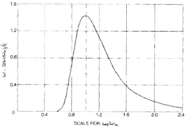
statistical descriptions and inputs, are defined in Sea Loads on Ships and Offshore Structures (Faltinsen 1990) and PNA, Vol. III. The Pierson-Moskowitz, JONSWAP and many other spectra are already part of and can be used for analysis in POSSE SMP. This procedure will use the Bretschneider spectrum (Figure 2.4) since it requires no additional statistical input other than significant wave height and period.
"U
0A
I
T-0.8 1.2
SCALE FRc wv-.-)
Figure 2.4 Normalized Bretschneider Spectrum (SNAME 1989, 3: 37)
The Bretschneider spectrum assumes it is reasonable to approximate a broad spectrum seastate without using as many statistical descriptors as some other spectra. The exceptions to the assumption are cases of unusual spectrum shape such as specific storm swells. However, for most general cases and ship seakeeping analyses, the Bretschneider spectrum yields good results
(SNAME 1989, 3: 38). Equation 2.18 gives a simplified version of the Bretschneider spectrum, S(?), where ? is the frequency, ?,n is the modal frequency, and ? is the significant wave height:
-1
1.25 W,42
S(O) = 'e
4 to
Equation 2.18. (Techet 2005, 9)
When using the Bretschneider spectrum, POSSE Ship Motions Program (SMP) calculates the modal frequency for the desired significant wave height and wave period (inputs).
2.3.2. Ship Motions - Theory
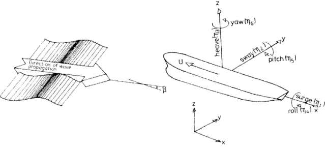
Describing ship motions in a seaway begins with the definitions of the ship motion in the cardinal directions (shown in Figure 2.5): displacements in the (x, y, z) directions (surge, sway, heave) are indicated respectively by the numbers (1, 2, 3), the rotational displacements around the axes of (x, y, z) (roll, pitch, yaw) are indicated respectively by (4, 5, 6).
1.6 2L 2.4
z CW 6
ro 714 7
Figure 2.5. Sign conventions for ship motions (Faltinsen 1990, 41)
The linearized Euler body force equation is given by Equation 2.19, where ?jk are the individual inertia elements for each direction, 71k are the accelerations in each direction, and
Fj(t) are the forces and moments acting on the body in each direction.
1 A Jklik (t)= F1(t)
k=1I
j=1,2,...6
Equation 2.19. (SNAME 1989, 3: 46)
Abkowitz (1969) linearized these equations for the case of a ship with lateral symmetry, yielding the equations of Table 2.3:
Table 2.3. Linearized Equations of Motion (SNAME 1989, 3: 46) surge A(j11 + z1n 5) = F sway A ( 2 - ZJ74 + X77) = F2 heave A (43 -C45) =F3 roll 14444 -46476 - Ac12)=F 4 pitch 1555 - A{z17 1 + Cj43 } = F5 yaw 6646 - 16444 - Ec2 =F6
where F,2,3 are the forces in each direction; F4,5,6 are the moments in each direction; ? is the
vessel mass; -e and Z are the coordinates of the center of gravity in the body-axis coordinate system(non- moving with respect to the ship (x,5, Z)); 144, '46' I55, 66, and 164 are all moments
of inertia about their respective axes; and 4k are the accelerations in each direction. Full definitions and development of what follows is shown in PNA Vol. III, Sec. 3. Each F can be broken down into a gravitational component, FGj, and a fluid force component, FHj:
Fj (t) = FGj + FH,
j=1,2,...6
Figure 2.6. (SNAME 1989, 3: 47)
The fluid force is given by Equation 2.19, where nj is the unit normal to the surface of the hull, P is the fluid pressure on the hull, and s is the underwater hull surface area.
FHj jffPnds
Figure 2.7. (SNAME 1989, 3: 47)
Assuming inviscid, irrotational flow, the pressure at any point on the hull, P, is given by
Bernoulli's equation, Equation 2.20, where ? is the fluid density, V F is the total fluid velocity, and Uo is the speed of the ship.
P=LpU2 - p -L p(VD X V(D) -pgz
E 2 at
Thus, the total fluid force (Equation 2.21) on the ship is found by a combination of the hydrostatic force, FHSj (Equation 2.22) and the hydrodynamic force, FHDj (Equation 2.23)
(SNAME 1989, 3: 48). FHj = FHSJ + FHD, Equation 2.21. FHSJ = -pg zn.ds Equation 2.22. FHDJ = -p U2 - -- }(VQ xVG) n ds Equation 2.23.
Solving for the hydrodynamic forces requires solving the total velocity potential for the fluid flow F (xy,z,t) by assuming it is a combination of both steady and unsteady potential. While this is discussed in detail in PNA Vol. III Sec. 3 (48-60) with full development of all terms of the hydrostatic and hydrodynamic force equations, it is important to be aware ofthe constituent forces which contribute to solving for the potential field. These forces, and the simplifications which allow for them to be solved for the two dimensional case, are what enable rapid
computation of ship motions using strip theory. The steady potential essentially consists of those forces which result from the forward motion of the ship in stillwater and are not time dependent
(wave resistance). The unsteady potential is a combination of the incident wave potential, the diffracted wave potential and the radiated wave potential. The incident wave potential are the forces that result from the integrated pressure of the applied sea wave over the hull: tle Froude Krylov force. The diffracted wave potential results from the forces which develop from the
scattering of incident waves. The radiated wave potential comes from a combination of the damping and added mass forces that result from a body moving or oscillating in a fluid. Each of these potentials are independent and can be superposed to develop the full velocity potential
field. The "linearized equations of motion" or six coupled, linear equations for the six unknown complex amplitudes, ff~k , are thus given by Equation 2.24: