Publisher’s version / Version de l'éditeur:
Journal of the Institution of Heating and Ventilating Engineers, 25, pp. 1-9,
1958-06-01
READ THESE TERMS AND CONDITIONS CAREFULLY BEFORE USING THIS WEBSITE. https://nrc-publications.canada.ca/eng/copyright
Vous avez des questions? Nous pouvons vous aider. Pour communiquer directement avec un auteur, consultez la
première page de la revue dans laquelle son article a été publié afin de trouver ses coordonnées. Si vous n’arrivez pas à les repérer, communiquez avec nous à [email protected].
Questions? Contact the NRC Publications Archive team at
[email protected]. If you wish to email the authors directly, please see the first page of the publication for their contact information.
NRC Publications Archive
Archives des publications du CNRC
This publication could be one of several versions: author’s original, accepted manuscript or the publisher’s version. / La version de cette publication peut être l’une des suivantes : la version prépublication de l’auteur, la version acceptée du manuscrit ou la version de l’éditeur.
Access and use of this website and the material on it are subject to the Terms and Conditions set forth at
Ground heat exchange problems
Brown, W. G.
https://publications-cnrc.canada.ca/fra/droits
L’accès à ce site Web et l’utilisation de son contenu sont assujettis aux conditions présentées dans le site
LISEZ CES CONDITIONS ATTENTIVEMENT AVANT D’UTILISER CE SITE WEB.
NRC Publications Record / Notice d'Archives des publications de CNRC:
https://nrc-publications.canada.ca/eng/view/object/?id=dbb44537-d0f7-482a-ab37-d5bc679b944b https://publications-cnrc.canada.ca/fra/voir/objet/?id=dbb44537-d0f7-482a-ab37-d5bc679b944b
Ser
TH1
N21r2
no.57
c.2
m4.3Canada
Division of
Buiidir~g
Research
Exchange
Problems
WILLIAM
G.
BROWN, B.Sc., M.Sc,
Research Paper
No.
57
of
the
Division of Building
ResearchReprinted by permission from the Journal of the Institution
of Heating and Ventilating Engineers, Volume 25, February 1958.
Price 25 Cents
Ottawa
June 1958
GROUND
HEAT
EXCHANGE PROBLEMS*
The Use of Models
and
Model Theory
By WILLIAM G. BROWN,t B.Sc., M.Sc.
SYNOPSIS
The use of models in deterniining heat exchange and temperatures for completely buried structures and structures in contact with the ground surface has been illustrated by model tests for both kinds of problem. Model data for two buried insulated pipes in close proxinlity have been analysed in detail and a test on a model of a basementless building was compared with field results for the prototype. In the latter problem the effect of surface radiation and convection was simulated in the model and agreement with field res~~lts indicated the feasibility of the model method for determining ground heat loss from buildings.
INTRODUCTION
M
OST problenis of heat excliange between buildings o r buried pipes and tunnels and tlie ground cannot b e solved adequately by simple heat equations because heat usually flows in complicated two- o r three-dinien- sional paths. As with problems of unidirectional flow such as building walls, tlie ground heat flow depends on temperature difference, on the thermal properties of components of the heated structure and ground through which it passes, and 011 the combined equivalent radia- tion and convection conductance of surface-air inter- faces. Unlike unidirectional problems, however, tlie ainount of ground heat excliange depends strongly on the shape of the heated structure and the shape of its coni- ponents, e.g. square or rectangular buildings with and without basements and insulation, and round or r e c t a n g ~ ~ - lar insulated pipes and tunnels. For these problems special methods of deterniining heat flow are necessary. Rigorous analytical niatliematical equations are not generally available for ground heat exchange although semi-empirical equations of the type developed by Maceyl are sometimes used for basementless buildings. The disadvantage of these equations is that they d o not take appropriate account of surface conductances and insulation arrangements. Semi-empirical equations are also available for single buried insulated pipes,Qut not for grids of insulated pipes and other complicated arrangements. Nuinerical relaxation methods which are capable of giving very exact solutions can sometimes be used for specific problems in two-dimensional heat flow but generally require a great ainouiit of calculation time." Manuscript received August 27th, 1957.
t Research Officer, Division of Building Research, National
Research Council, Ottawa, Canada.
When three-dimensional problems are involved the required calculation time would be prohibitive.
Due to the limitations of mathematical methods, data for buildings are sometimes obtained by specific field tests.3 Tliis method is generally limited by costs, however, and tests are usually carried out on narrow floor sections. The absolute magnitude of the heat exchange for long buildings may be fairly well established in this way but tlie merits of various insulation arrangements may not be apparent because fluctuating weather conditidns aiid difficulties of heat flow measurement cause considerable uncertainty in interpreting results. One further disad- vantage of this method is that data a r e usually applicable only to buildings of the size tested.
Heat exchange information can also be obtained by the use of electrical analogues. Bil1ingtoii"eports network analyser results for two-diinensioiial flow in floors of various widths, with and without insulation. This method is extremely rapid but has disadvantages similar to those of the relaxation method in that the coniponents of tlie heated structure and ground are represented by a network, in this case, of electrical resistors. Accuracy depends on the number of resistors employed, thus the method generally would not be feasible for three-dimensional problems where a great nuniber of resistors would be required.
One additional method of solving ground heat ex- change problems is by the use of models. Altliougli the advantages of this method liave long been known, apparently it has not yet seen significant application, and information on its practical feasibility is necessary. Tliis Paper deals with tlie construction and testing of two models: tlie first, a buried pair of insulated pipes; the second, a inodel of a baseinentless building.
Theory of Models
F o r the solution of all problems of heat exchange by conduction in solids and radiation aiid convection at surfaces, tlie theory of models5 shows that for steady- state lieat flow all components of both inodel and prototype inust liave identical geometry a n d the same values for the following two dimensionless groups of variables, i.e.
and
. .
. .. .
. .
(2) Where subscript i n refers to model and ,f' to field orQ is the heat transfer rate; either tlie total heat flow or the flow at any corresponding locations in model and prototype.
I< is the thermal conductivity of corresponding com-
ponents in model and prototype.
L is any corresponding length in model and proto- type.
AT is any teniperature difference between correspond- ing pairs of points in model and prototype.
11 is the equivalent combined convection and radiation lieat transfer conductance for corre- sponding surfaces in model and prototype.
When time considerations are involved (e.g. the annual weatlier cycle or sudden weather changes) one other dimensionless group must be satisfied:
where u is the thermal diffusivity of corresponding com-
ponents of tlie model and prototype, and t is tlie time. The advantages possible with the niodel nietliod are apparent from the theory. By testing small-scale replicas oS field structures simulated weatlier conditions can be controlled. Size reduction, also, suggests savings in construction costs and, as indicated by equation (3), tlie time required to obtain data with a model is much less than for field tests. It is notable, however, that difficulty might arise in achieving proper simulation of the equiva- lent surface co~iductance 11. In the field, 11 generally varies over an inside surface, such as a floor, due to its dependence on the temperature difference between surfacc and ambient air and surroundings. Obviously, a ~iiodel attempting to si~iiulate a variable 11 would not be practically feasible, thus one of the first studies of the applicability of models would be to determine if it could be replaced by an average constant value. This was done in tlie construction of tlie niodel of the basementless building. Before describing this work, liowe\/er, the simpler pipe model tests will be discussed.
MODEL OF A PAIR OF INSULATED BURIED PIPES
Altliougli problems involving heat exchange and tem- perat~lres for buried pipes and tunnels are many and varied, their treatment by ~iiodels would be similar. T o illustrate the niethod one specific problem is presented here in co~isiderable detail.
One way of both reducing heat loss and protecting buried high-temperature pipes from corrosion is t o insulate the pipe arid apply a layer of asplialt to the outside of the insulation. One of the main purposes of the insulation is to ensure low temperatures in the asphalt t o prevent softening. Occasionally, however, the insulation may be wet when installed and have a conse- quent high thermal conductivity. Under these conditions tlie temperature in the asphalt coating may reach the softening point.
T h e proble~nconsisted of determining the temperatures and heat loss which would occur with two 1-in diameter
pipes (1.315 in O.D.) surrounded by 1 in of wet insula- tion and covered with a I-in layer of asplialt. T h e covered pipes were laid one upon the other and buried 4 ft deep in normal moist soil.
Since asphalt has about tlie same ther~iial conduc- tivity as moist soil tlie model was planned s sing only o n e material to represent both. Powdered plaster of Paris and dry paper were chosen to represent the ground and wet pipe insulation respectively. In a separate test using a hot-plate apparatus the thermal conductivity of the paper was foulid to be 0.050 B.t.~l./h/"F/ft, and tlie thermal conductivity and diffusivity of tlie plaster of Paris were found to be 0.075 B.t.u./li/"F/ft and 0.0047 ft'/li respectively ~ ~ s i ~ i g the line lieat source met11od.c Since the thermal conductivity of asplialt is about 0.44 B.t.u./h/"F/ft, equation (1) shows that tlie conduc- tivity of the wet field insulation si~iiulated by the model would be
(The conductivity of water alone is 0.4 B.t.u./h/"F/ft.) Heat exchange between the ground surface and the air above is not generally important for problems of buried structures. This can be clarified by considering t h e ~lsually accepted value for the surface coeffici=nt o r equivalent conductance of 12 = 6.0 B.t.u./li/OF/sq ft. Since 11 is a thernial conductance, it is equivalent to a n extra layer of soil on tlie ground surface and its tliiclcness can be calculated. Assuming a soil conductivity o f
lc 0.5
(3.5 B.t.u.,/Ii/"F/ft, this thickness is =
11 6.0 = 0.08 st. Obviously, for a struct~lre buried several feet deep tlie error due to neglect of this extra length oS heat flow path would be negligible and the ground surface temperature could be assumed equal to the air temperature.
Construction o f t h e Model
The model (Figs. 1 and 2) was built exactly t o tlie scale of 1 : 21, i.e. tlie model pipe was a 0.0625-in O.D. brass t ~ ~ b e buried 2.28 in deep. T h e supply and return pipes were formed by looping the tube, a n d the completed niodel was installed in a box 14 in wide by 18 in long by 6.75 in deep containing the plaster of Paris. Heating was obtained by connecting the upper pipe (supply) to a liot- water source. T h e top surface of the plaster of Paris was covered by a thin copper plate and maintained at con- stant temperature by means of a fan blowing over it.
Two sets of 36-gauge butt-welded copper-constantan thermocouples were installed 4 in apart at the supply a n d
CONNECTION --- -- I @ ' ' A- - -
-
TO HOT WATER 1 - r r
I
m / f l A :
Fig. I.-General arrangement of buried pipe model.
2 SUPPLY--- / € J L , / , / TROUGH THERMOCOUPLE P O S I T I O N S r---- YE --- I
-
6' ---
4" -1--
6"-
PLASTER OF PARIS I P O W O E R E D I I2 2 8 " TO SURFACE 1 0 126"
I
\ \ \ ; I \.
-L_ 1 -.
,--0 - - --
.
,.
, 2 2 8 " TO SURFACE 10 0 6 2 5 " O 157" I \ 0 126" \ \ \ -L_ 1.
On completion of the first test the insulation was removed from tlie loop end of tlie pipe and a copper rod inserted in tlie loop to increase tlie cooling and give lower pipe return temperatures. With this condition the pipe heat flow could not be measured, since the amount of heat extraction at the copper rod was unknown. However, temperatures were recorded for comparison with the first test.
/
,
-.
- - --
,Fig. 2.-Cross-sectional view of model pipes.
return pipes to measure pipe and insulation surface temperatures and the mid-point temperature (equivalent to the asphalt surface temperature). The surface tem- perature of the plaster of Paris and the ambient air temperature were also recorded.
Procedure
Two tests were made at different supply and return pipe surface temperatures. Control was manual by water flow regulation, since test duration was only a few hours. In
the first test the s ~ ~ p p l y and return pipe temperatures were maintained nearly equal and temperatures were recorded from the beginning of heating to determine both the time-dependent and equilibrium temperatures. The water flow rate was recorded and the heat exchange calculated from the equation:
where q = the heat flow per unit length of double pipe,
I V = the mass flow rate of water,
C, = the specific heat of water,
AT = the teniperat~~re rise along the total pipe length,
L = the length of the double pipe (half the total length).
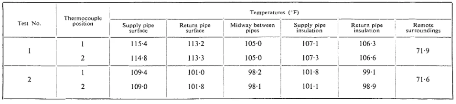
TEST RESULTS AND CALCULATIONS Temperatures
Observed temperatures at the pipe and insulation sur- faces and mid-way between the pipes (Fig. 3) showed the characteristic time dependence for the first hour of test. Equilibrium was reached after about two hours. Average equilibrium results for the last half-hour of both the first and second tests (Table I) arz not directly con~parable, since 110 constant reference telnperature was maintained,
i.e. constant supply or return pips temperature.
In order to compare equilibriu~n results on a similar basis and to determine what temperatures would occur in the field with pipe temperatures as high as 365°F the data must be converted in accordance with model theory.
LL
,,,
100 a AY BETWEEN P a W TIME IN MINUTESFig. 3.-Temperature-time relationship for model pipes. (Averages for thermocouple positions I and 2.)
Table I.-Equilibrium Temperatures in Model Pipe Tests.
Temperatures ( F)
Thermocouple -
-Test No posltlon
I
SUF,"~'~;P~ Return p ~ p eI
M ~ d w a y between 1 Supply pjpe RemoteI
/
surface,
pipes ~ n w l a t ~ o n?ZZ'tP,',"'
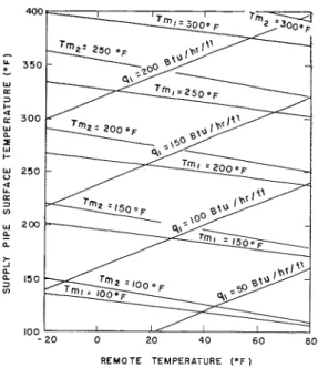
s u r r o u n d ~ n g sEquation (1) and its restrictions show the only criterion to be that all temperature differences in the field must bear a constant ratio to corresponding temperature differ- ences in the model. Field temperature profiles obtained from the model data in this way (Fig. 4) show the effect of varying tlle pipe surface temperatures with constant remote or surrounding temperature. The effect on the temperature midway between the pipes caused by varying both pipe surface and remote temperature is shown in Fig. 5. Results indicate that with the soil and iilsulation conditions simulated by the model the tem- perature of the asphalt would reach 210°F, its softening point, if tlle supply pipe temperature was about 260°F to 280°F.
The time to reach equilibrium in the field can be calculated from results for the first model test using equation (3). According to Kersten,7 a silt or clay soil having a tllerinal conductivity of 0.44 B.t.u./h/"F/ft and a density of about 95 lb/cu ft would have a moisture content of 10 per cent. and a specific heat of about 0.3 B.t.u./lb/"F. The thermal diffusivity can now be obtained from the relationship
It
= ---
P
G I
where p is the density and C?, tlle specific heat. Hence
a = 0.44 t 95
x
0.3 = 0.016 fte/h. The diffusivity of the plaster of Paris in the inodel was 0.0047 ft2/h. I11 tlle model, equilibrium was reached in about 2 11, hence equating equation (3) for both model and field yields:0.0047
Time to equilibrium in the field = 2
x
x
21V1 0.016R E M O T E TEMPERATURE ( O F 1
Fig. 5.-Variation of heat loss and mid-point temperature w i t h supply pipe surface temperature and r e m o t e sur- roundings temperature. Tm,, Tm,, q,-mid-point temperatures from first and second model test and heat
loss f r o m first test respectively.
Equation (1) can now be used to determine the field heat flow. Rewritten it becomes:
= 10 days.
Q
0.44Substituting q = - a n d the ratio of conductivities -
L 0.075
Heat Loss gives :
The temperature difference between supply and return
pipes at thermocouple position 1 was 2.2"F and the qf = 4~6(:ff74~).
($2)
= 27(-ATf) A Till B.t.a./h/ft.water flow rate was 1.8 lb/ll. The total length of single
pipe involved was 1.71 ft, hence from equation (4) the Heat losses calculated from this equation for different heat loss per ft of double pipe was: values of
($:;),
i.e. different pipe and remote tenlpera-2
q711 = 1.8 x 1.0
x
2.2x
- - = 4.6 B.t.~./h/ft.1.7 1 tures, are given in Fig. 5.
Conversion of Results t o Other Condit~ons
The temperature and heat flow results obtained in heating tests either with a inodel or 111 the field can be
, -
converted directly to cooling problems and for other soil and insulation thermal properties and different pipe
MID VIAY sizes. Cooling problems simply require negative tempera- BETVIEEN
PIPES ture difference ratios and negative heat flows; thus
equation (1) is used without change. I11 order to use results for other thermal property or size conditions the proper- ties or sizes of each new component inust bear the same
RETURN PIPE ratio to those of other components. For example, the S ~ R F A C E 100 I 2 0 140 160 180 2 0 0 2 2 0 2 4 0 2 6 0 2 8 0 3 0 0 3 2 0 3 4 0 3 6 0 3 8 0 4 0 0
temperatures obtained in tlle present tests would also be
TEMPERATURE "F
obtained with 2-in diameter pipes buried 8 ft deep or Fig. 4.-Calculated equilibrium temperatures between buried pipes. 3-in diameter pipes buried 1 2 ft deep provided- the I, 2-data from first and second model tests respectively. (Remote insulation thickness and pipe spacing were proportional
u W 5
s
W 5 F I G 6 (01-- HEAT LOSS 2 2 0 F I G 6 ( b lFig. 6 (a).-Characteristic undisturbed annual ground temperature variations. (Ottawa, Canada, region f o r sandy soil.) Fig. 6 (b).-Annual variation i n heat loss and temperature mid-way
between pipes buried 4 ft. deep.
Effect of the Annual Weather Cycle
In the field the temperatures in the ground do not remain constant but vary throughout the year under the influence of the annual weather cycle. (Typical ground tempera- tures are given in Fig. 6 (a).) Although the effect of the weather cycle could be simulated in a model by varying the ground surface temperature, generally this would not be necessary, since field results can be treated as steady- state for short periods of time with little loss ofaccuracy. This is true because in the ten days required for the field pipes to reach equilibrium the ground temperature changes only slightly due to the weather cycle. For constant supply pipe surface temperature the nlodel results can be converted to field conditions by use of the teinperature superposition principle.6 For this purpose the difference between the supply pipe surface tempera- ture and the undisturbed ground temperature at the pipe depth will correspond to the model temperature differ- ence between pipe and surroundings and thereby deter- mine the temperature difference ratio. The heat loss from the pipe at various times can then be determined from equation (1). Results of these calculations for several supply pipe tenlperatures are given in Fig. 6 (b). Treat- ment of the model data for any other supply pipe temperature would be similar.
MODEL O F A BASEMENTLESS BUILDING
As indicated in the introduction, the feasibility of models when surface heat exchange is important is conditional on agreement between field data and data obtained with a model using a constant average surface conductance / I .
T o determine the degree of agreement which could be expected in practice, a model was built to simulate an existing instrulnented basementless building.
The prototype building consisted of a 6-in thick concrete slab, 20 ft square, lying directly on the ground and heated by electric cables on 1.56-in centres embedded 3 in deep in the slab. Glass fibre edge insulation, 1 in thick, extended 12 in below the top slab surface around the periphery. Instrumentation consisted of thermo- couples at various points on the upper and lower surfaces of the slab and in the ground beneath. Heat meters on the upper surface of the slab measured upward heat flow; downward heat flow into the ground was determined by subtracting the upward heat flow from the heat equiva- lent of the electric cable power input.
1
The model size was chosen arbitrarily as about - -
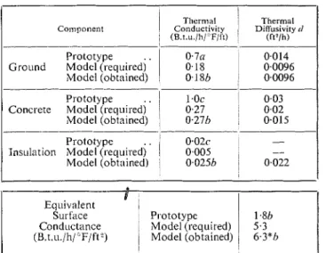
10 that of the prototype (actual scale 0.0916), and dry sand was chosen to represent the ground. Application of equation (1) then determined the required thermal con- ductivity of the model slab and its edge insulation. (The properties of the ground, concrete and insulation for the prototype and model are given in Table 11.) For the model slab a suitable nix of vermiculite concrete was
Table //.-Thermal Properties o f the Components o f the
Basementless Building and i t s Model.
Thcrnial Thermal Component
1
Conductivity DiWurivity i1 ( B . t . u / l i / F / t ) ' (ft3/h)
Prototype 0.7a 0.014
Ground Model (requiredj '
1
0.18 0.0096Model (obtained) . 0.18h 0.0096 prototype
..
!
1 . 0 ~ 0.03 Concrete Model (required) ! 0.27 0.02 Model (obtained) 0.270 0.015Prototype 1 0 . 0 2 ~ 1 -
Ins~~lation Model (requiredj '
1
0,0051
Model (obtained)
/
0,0250 0.022I !
Eq~~ivalent I
Surface
I
Prototype1
1.80 Cond~~ctance Model (required) 5.3 (B.t.u./h/"F/ft" 1 Model (obtained) / 6.3*h a Obtained from reference 7 using measured density and mois- ture content data.h Obtained by direct test.
c Obtained from handbook data.
/c
d Obtained by relationship a = - n r n
r -1-
where: a = thermal diff~~sivity k = thermal conductivity
p =density
Cp = specific heat
* Simulated by a 0.25-in thick plate of lucite plastic (k = 0.13 B.t.u./h/"F/ft at the model test temperature).
CONSTANT TEMPERATURE WATER TANK 14" THICK INSULATION
7
1
% % o q H A L F SLAB AND ROOM AIR TANK. GROUND SURF TANK HEAOER (ARROWS SHOW CIRCULATION) -- RETURN TO PUMPSUPPLY FROM
PUMP^
TOP VIEW TANK OVERFLOW
OUTSIDE GROUND
SURFACE TANK Yp7 ROOM AIR
h 1 n TANK
7
TANKI
2' INSULATION RESERVOIR SECTION A-A S C A L E --
0 I l l F i g . 7.-General l a y o u t of b a s e m e n t l e s s b u i l d i n g model s h o w i n g a u x i l i a r y e q u i p m e n t .obtained after thermal co~iductivity tests in a hot plate. For the edge insulation, however, it was necessary to use a thickness of insulation greater than that called for by geometrical identity to ensure that horizontal heat flow would be similar in liiodel and prototype. This was necessary because no known insulating material had the required low conductivity.
The average required surface conductance h,,, of the model slab was obtained fro111 equation (2) using the average measured value of /if for tlie prototype slab. In
the field tests the indoor air and wall and ceiling tem- peratures were almost identical (7OoF), and the average value hf was determined by area-weighted averaging of individual values at each heat meter position. For this purpose the individual values of 11 were determined from the equation:
where q' is the heat flow per unit area in the region covered by each heat meter and AT is the temperature difference between the slab surface and surrounding air. In the model the surface conductance was simulated by a 0.25-in thick plate of lucite plastic. Values of hf, required and obtained values of h,,, are given in Table 11.
In the field tests no record was kept of snow cover on the ground surface and no attempt was made to estimate the actual magnitude of the equivalent thermal conduc- tance of the out-of-doors convection and radiation sur- face heat exchange. The ground surface temperature appeared to be nearly uniform, however, hence the model was designed to be operated with uniform constant ground surface temperature.
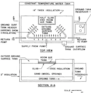
The model and its auxiliary equipment are shown in Fig. 7. Copper tanks containing circulated water were
installed directly over the lucite "surface conductance", surrounding the model slab and underneath the model ground to simulate constant room air temperature, ground surface temperature and the ground temperature corresponding to a depth of 16 ft under the field slab respectively. Temperatures were controlled to within 0.3"F by thermostatic regulation of electric immersion heaters. Regulated direct current power was used to supply the heat input to the 30-gauge constantan heater wires in tlie slab. Thern~ocouples were installed through- out the model ground and on the slab surface at points corresponding to those in the field.
To save space only half the model was constructed a n d the dividing plane was insulated to reduce heat loss. A narrow. vertical. water-containing guard tank was
- -
installed on the outside of the insulation and maintained at the approximate mean temperature of the model t o further reduce heat loss. Although the use of onlv half-
the model would distort the heat flow and temperature rtgime in the region of the dividing plane, these distor- tions would not Denetrate far under the slab and test results for tlie region near the slab edge insulation would be typical for a coniplete model. The total heat flow over the half slab was not expected to agree too well with field results, but it was measured anyway to illustrate the method of determining heat flow for problems of this kind.The heat flow into the model ground was obtained by subtracting the heat flow upward from the measured slab power input. The heat flow upward was determined by a separate test in which a calibrating tank was placed in the position of the slab and kept at the same tempera- ture as the room air tank above the lucite plate. The measured power to the heater and pump of the room air tank systelil then consisted of the environmental losses less the heat flow which would be received from the slab. Since environmental losses were the same with the slab in place, tlie difference in the power requirements of the
C O V E R I N G 8 0 X I / GUARO INSULATION , - C O V E R / S T A N D P I P E
i
i
ROCKWOOL I N S U L A T I O N , I , .'? , :\I
ONAZOTE INSULATIOK1
p w ,
OUTSIDE GROUND SURFACE TANK INSULATION L A Y E R ---EDGE INSULATION --_-CIRCULATION HEAOER , - C A L I 8 R A T I N G TANK(OR MOOEL SLAB1 SANO
Fig. 8 . - H e a t flow m e a s u r i n g a p p a r a t u s for b a s e m e n t l e s s b u i l d i n g
room air tank during the two tests gave the net upward heat flow. Details of the apparatus are given in Fig. 8. Preliminary tests showed that the environmental heat losses fluctuated considerably due to variable natural convection over the top surface of the room air tank. These fluctuations were eliminated by enclosing the tank and its pump in a box containing a circulating fan.
Procedure
One complete steady-state test was made to study the behaviour of the model under conditions which most closely approxitnated those in the field. The field heat flow and temperatures (Table III) were taken as the averages observed during the month of January.
The model test was made with the same "equivalent" slab heat input, room air temperature, outside ground surface temperature and deep ground temperature as for the field slab. The model ground surface temperature was arbitrarily set a t 97OF and the model room air tempera- ture set at 156"F, the teinperature difference being 59 deg. F. The corresponding temperature difference in the field (Table Ill) was 36 deg. F, hence all model temperature differences should be in the ratio 59 t 36 = 1.64 to those in the field. The field temperature 16 ft deep under the slab was 52°F and the difference between this and the room air temperature was 70 - 52 = 18
deg. F. In the model this corresponds to a temperature difference of 18
x
1.64 = 30 deg F. The actual required temperature in the model is then 156 - 30 = 126°F. The total heat input to the model slab was determined using equation (I), i.e.The field heat input was 13 200 B.t.u./h (TableIII), the 0.18
ratio of conductivities (Table II) was 077, the length ratio was 0.0916, and the ratio of temperature differences 1.64, thus the required model heat input was:
Since only half the model was tested, the net requirement was 255 B.t.u./l~. Wit11 this value of total heat input and the appropriate room air, ground surface and deep
Table Ill.-Heat Flow and Temperatures in Field and
Model Tests
Total slab heat input . . Heat flow upward . .
. .
Heat flow into ground. .
Room air teniperat~~re . . Remote ground surface tem- perature . .. .
. . Ground t e m p e r a t ~ ~ r e 16 ft deep Model Test i 13 500 B.t.u./h 8 600 B.t.~l./h 4 800 B.t.u./h 70°F 34°F 52 F --" Average results for January.
.t Converted to equivalent field conditions.
ground temperature, the other temperatures in the model ground and on the slab surface were recorded for com- parison with field results. On completion of the test the slab was removed and the calibrating tank installed to determine the upward and downward heat flow.
Results and Discussion
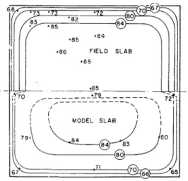
Temperatures o n the upper slab surface in the model and field (Fig. 9) were in essential agreement except near the dividing plane of the model. In the central region of the slabs temperatures differed by about 2 deg. F. The tem- peratures differed more, about 4 5 deg. F, closer to the edge insulation. The proportion of the total heat input flowing upward and downward in the model (Table 111) agreed well wit11 field results, but telnperatures in the
-86 FIELD S L A B
- 6 5
-
Fig. 9.-Isotherms on the top slab surface of the basementless building and its model. (Points repre- sent thermocouple positions in the model and heat
meter positions in the field.)
SLAB HEATED CONCRETE SLAB
CENTRE I I h E EDGE INSULATION FIELD SCALE
<
/
MDDEL ISDTHERMS -0-/
5 MDDEL SCALE-
0 , 8" ',
-fa-----_
Fig. 10.-Ground temperatures under the basementless building and its model.
3 0 3 5 40 < 5 50 55
T E M P E R A T U R E ( O F )
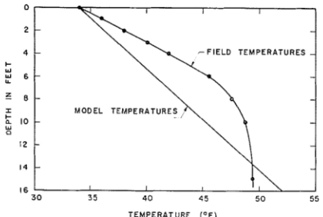
Fig. I I.-Measured field ground temperatures remote from the basementless building and imposed ground temperatures in t h e
model.
ground beneath the slabs (Fig. 10) differed by as much as 10 deg. F.
The relatively poor temperature agreement under the slab centreplane undoubtedly was caused by the use of the half niodel. In the central region, under the slab edge insulation, however, much of the difference was due to the influence of the annual weather cycle on the field temperatures. This can be best illustrated by comparing the vertical temperature distribution in the remote ground of the field and niodel (Fig. 11). At this location the field temperatures are almost entirely due to annual weather variations and show tlie characteristic non-linear temperature gradients, whereas the model temperatures would show a linear gradient if the niodel ground extended indefinitely outward. Tlie field temperatures are all considerably higher tlian those of tlie model, as much as 52 deg. F at 8 ft of depth. This effect would also extend up to and under the slab, hence field temperatures as noted in Fig. 10 would be somewhat higher tlian those of the model.
Although operating the niodel with steady-state con- ditions resulted in poor ground temperature agreement with field results. the effect on heat flow would not be so pronounced. This is true because, as indicated by the isotherms, most of tlie heat flow occurs near the slab edge where model and field temperatures are in best agreement (Fig. 10).
Effect of Air Spaccs
N o special attempt was made to ensure elimination of thin air spaces between the model slab and lucite plate and between the lucite plate and room air tank. However, approximate calculations showed the effect to be small. With a total air space thickness of between 0.005 in and in the error in downward heat flow would be between 2.5 and 10 per cent. Slab surface temperatures under these conditions would be between 2 deg. F and 5 deg. F too high. Since the conductance of the lucite plate was somewhat higher than called for by model theory, the effect of a small air space would tend to be cancelled out.
GENERAL DISCUSSION
The essential agreement of slab surface temperatures and heat flow for the basementless building and its model has indicated the feasibility of the model method in obtaining data. With this established it appears that the method would be suitable for most ground heat exchange prob- lems. One immediately useful application of the theory is the extrapolation of existing data to different tempera- ture conditions. For example, with heating data available for any particular type of building, cooling loads and ground temperatures during cooling can be calculated. This is probably the most accurate method of estimating cooling effects, because approximate account is taken of air-surface heat exchange and variations due to the annual weather cycle. An exan~ple is given in the Appendix.
The results of the model pipe tests illustrate the time saving possible with this method. Complete construction and tests on the model required only 24 man-hours, whereas about ten days would be required in the field just to reach equilibrium conditions after applying heat. Specific model tests for this kind of problem, therefore, are entirely practical. Tlie construction and testing of the basementless building model obviously required much tinie due to tlie auxiliary equipment requirements. Although field tests for tliis kind of problem are usually continued for one or more years the model method appears most suited to a continuing project for the study of different shapes and kinds of buildings with and without insulation.
Choice of Test Materials
For further model work of tliis kind some recom- mendations are in order. Considerable time was spent during thc development of the model basementless building in finding materials to simulate the soil, insula- tion and concrete. Indeed, it was not possible to have geometrical identity in the edge insulation nor was it feasible to attempt time-dependent tests because the model components did not have appropriate thermal diffusivities. These difficulties could be largely eliminated if actual field materials were used for the dry components of the model. Only one chosen material would then be necessary to represent the gt-ound. With these conditions both steady-state and time-dependent tests could be made. F o r the model ground, a sample of the field ground itself might be used, although some complica- tions might arise in attempting to maintain the same average moisture content as in the field. If this should prove feasible, however, a further refinement could b e added by using the same boundary temperatures in the model as in the field, since the thermal properties of materials generally depend somewhat o n temperature. The same considerations could be given to problems of completely buried structures. In the second model pipe test heat flow could not be measured, since the tempera- ture change of the water in traversing the pipe was t o o small for accurate measurement. This difficulty could be eliminated by supplying heat electrically with constantan heater wires inside the pipes.
CONCLUSION
The usefulness of the model method for determining heat exchange and temperatures for completely buried structures and structures in contact with the ground surface has been indicated by representative model tests for both kinds of problem. The basementless building inodel showed the feasibility of simulating the effect of surface radiation and convection heat transfer by an equivalent conductance. Due to the equipment and apparatus requirements, however, the use of models for problems of this kind is best suited to a continuing project for studying various types of buildings. For moderately simple buried structures, such as pipes, considerably less apparatus is required and the model method offers a rapid and inexpensive means of obtaining data.
ACKNOWLEDGMENTS
This Paper is a contribution of the Division of Building Research of the National Research Council of Canada and is published with the approval of the Director. Appreciation is due Messrs. G. Starke, J. S. Keeler and
M. J. Laubitz for portions of the design and testing of the basementless building model. Messrs. B. Brule,
J. Berndt and W. Podd assisted with the construction and instrumentation.
REFERENCES
MACEY, H. H.: "Heat Loss Through a Solid Flool.," J. Illst. File/, October, 1949, 22, (128).
"ALLEN, J. R.: "Theory of Heat Losses fro111 Pipes Buried in the Ground," Trn~ls. A.S.H.V.E., 1920, 26, p. 335.
BAREITHER, H. D., FLEMING, A. N., and ALBERTY, B. E.: "Tem- perature and Heat Loss Characteristics of Concrete F l o o ~ s Laid on the Ground," University of Illinois, Small Homes Co~lncil, August, 1948. PB 93920, 50 pp.
BILLINGTON, N. S.: "Heat Loss through Solid Ground Floors," J.I.H. V.E., November, 1951, 19 (195), pp. 351-72.
JAKOB, M.: Herr/ Trollsfel., Vol. 1, John Wiley & Sons, Inc., New York, 1950.
"NGERSOLL, L. R., ZOBEL, 0. J., and INGERSOLL. A. C.: Hear Coircltrctio~r. Revised Edition, University of Wisconsin Press, Madison, Wis., 1954.
KERSTEN, M. S.: "Thermal Properties of Soils," Highway Research Board, Special Report No. 2. Symposiun~ on Frost Action in Soils, Washington, D.C., 49 pp.
APPENDIX
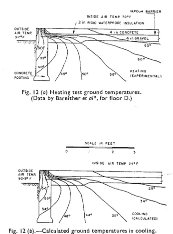
DETERMINATION OF TEMPERATURES UNDER A REFRIGERATED BUILDING FROM HEATING DATA To illustrate the method of converting ground tempera-
tures to new conditions, heating data by Bareither et al,"
(Fig. 12 ( a ) ) can be changed to cooling conditions. The inost accurate results are obtained if the effect of the annual weather cycle is accounted for. Since this cycle causes approximately sinusoidal annual ground tem- perature variations, the temperature differences in the ground will be approximately equal but opposite in sign at two opposite times of year. Hence winter heating season data are most accurately converted to summer cooling. In Bareither's tests the indoor air temperature was 7 0 ° F , i.e. about 23°F above a mean annual ground temperature of 47°F (Fig. 6 (a)). The most accurate cooling temperatures would then be obtained if the indoor air temperature was 47 - 23 = 24°F. Since the annual weather cycle requires all temperature differences to be equal but opposite in sign for heating and cooling, the new outside air temperature would be 24
+
( 7 0 -3.7) = 90.3"F. All other temperature differences are treated similarly and results are given in Fig. 12 (6).
In the above calculations the equivalent surface conductance was assumed to be the same for both heating and cooling. In practice this would not generally be true. It will be appreciated, however, that this calcula- tion method which takes approximate account of h is superior to purely mathematical methods which generally assume constant or arbitrary surface temperatures.
VAPOUM B 4 R R I E R INSIDE AIR T E M P 7 0 ° F
CONCRETE FOOTING
Fig. 12 ( a ) Heating test ground temperatures. (Data by Bareither et a13, for floor D.)
SCALE IN F E E T
I_
-
5 I 2 3
I N S I D E AIR T E M P 24'F