A Constraint Framework for Analysis of
Engineering Systems
by
Shannon Jun Ho Iyo
MASSACHUSETTS INSTiTUTU MASSACHUSETTS INSTITUTE OF TECHNOLO ',
NOV
1
3
2008
LIBRARIES
6.B3., C.S. M.I.T., 2006Submitted to the Department of Electrical Engineering and Computer
Science
in partial fulfillment of the requirements for the degree of
Masters of Engineering in Computer Science and Engineering
at the
MASSACHUSETTS INSTITUTE OF TECHNOLOGY
Feb 2008
@ Massachusetts Institute of Technology 2008. All rights reserved.
Author ...
...
...
Department of Electrical Engineering and Computer Science
January 25, 2008
C ertified by ... . ... ..
... ...
U "
Daniel E. Hastings
Professor of Engineering Systems and Aeronautics and Astronautics
Th sis Spervisor
Accepted by...
...
...
Arthur C. Smith
Professor of Electrical Engineering
Chairman, Department Committee on Graduate Students
ARCHIVES
A Constraint Framework for Analysis of Engineering Systems
by
Shannon Jun Ho Iyo
Submitted to the Department of Electrical Engineering and Computer Science on January 25, 2008, in partial fulfillment of the
requirements for the degree of
Masters of Engineering in Computer Science and Engineering
Abstract
This thesis presents the design and implementation of a constraint framework for use in analyzing engineering systems. This framework extends the Engineering Systems Matrix to allow the definition of quantitative relationships between model objects. The addition of formal quantitative constraints allows analysts to make use of new techniques and simplifies maintenance of the data model.
Thesis Supervisor: Daniel E. Hastings
Acknowledgments
I would like to thank Professor Hastings for his patience and support of this project. Also thank you to Jason Bartolomei and Igor Sylvester for their hard work and good ideas upon which this thesis is built. And finally thank you to Reesa Phillips, Jennifer Wilds, David Broniatowski, and Nirav Shah for all the hard work, advice, and help.
Contents
1 Introduction
1.1 Background ... 2 Engineering Systems and the ESM
2.1 Engineering Systems ...
2.2 The Engineering Systems Matrix ...
3 The Frog Analysis Tool
3.1 System Design ...
3.1.1 Data Representation 3.1.2 Naming Conventions 3.2 System Implementation...
3.2.1 Server Architecture.
4 The Constraint Framework
4.1 Design ... . .. . .. ... 4.1.1 Equation Syntax ...
4.2 Implementation ...
4.2.1 Data Representation ...
4.2.2 Additional Server Commands . . . .
4.2.3 Equation Evaluator . . . ... 4.2.4 Constraint Invariants . . . . 4.2.5 Constraint Graphical User Interface .
17 .. . .. . . . .. . . . 18 . . . .. . . .. . . . 18 . . .. . . .. . . . 18 . . . .. . . .. . . .. . . . 19 . .. . . .. . . . 2 2 . . . .. . 27 . . .. . . . . . .. . 28 . . . .. . . . . . . 30 . . . . .. . 30 . . . . . . . . . 32 . . . . . . . . 33 .. . . . . . . 34 . . . . . . . . . 35
5 Conclusion
5.1 Contributions . . . . 5.2 Known Issues . . . . 5.3 Future Work ...
A Selected server source code
A.1 Spidr.java ...
A.2 SpidrEnvironment.java . . . . A.3 SpidrDatabase.java . . . .
A.4 Attribute.java . . . ... A.5 Constraint.java . . . . B Selected user interface source code
B.1 ConstraintPanel.java ... B.2 ConstraintListCellRenderer.java . B.3 CreateConstraintDialog.java . B.4 EquationTextPane.java ... 43 43 43 44 47 47 58 61 62 67 ..... . . . . . . . . . . . . . ..... . . . .. . . . . . . . . .. . . . . . . . . . . . . ..
List of Figures
2-1 The Engineering Systems Matrix . ... . 15
3-1 Inheritance property of nodes ... ... 19
3-2 Example of naming conventions ... .. 20
3-3 Frog application architecture ... ... 21
3-4 Class structure of the Frog server data model . ... 23
4-1 The constraint list user interface ... .. 37
4-2 The first constraint input interface design . ... 38
4-3 The drop-down list in the first constraint input interface ... 38
4-4 The second constraint input interface design . ... 39
4-5 Auto-complete step 1 ... ... 40
4-6 Auto-complete step 3 ... ... 40
4-7 Auto-complete step 3 ... . ... .. 40
5-1 The search box ... .. . ... 45
Chapter 1
Introduction
Systems in the real world are often large and complex, with many interacting com-ponents, and because of this there are many interesting real-world systems that are not understood in great detail. For example, a restaurant is far from the most com-plicated of but is quite complex nonetheless. There are a number of people involved, all performing different tasks and interacting with each other and with people outside the organization to reach a common goal. In order to make better decisions in sit-uations involving complex real-world systems, it is important to try and understand such systems in greater depth. For example, one might study the restaurant in order to determine which people or positions are the critical links in the restaurant's day-to-day processes, and reassign duties appropriately. This thesis describes the extension of a methodology for performing this kind of analysis.
Chapter two of the thesis describes the Engineering Systems Matrix (ESM) method-ology for capturing a general system, which is used to model real-world systems for formal analysis.
Chapter three covers the design and implementation of the Frog software tool, which is a Java-based application used to analyze ESMs.
Chapter four is about the design and implementation of the constraint frame-work, which adds numerical capabilities to the ESM and to the Frog application. It also describes the user interface that was created for interacting with the constraint framework.
Chapter five discusses the contributions made by this thesis, lists known issues, and describes possible future directions of research.
1.1
Background
The work executed in this thesis is built upon previous work at the Massachusetts Institute of Technology. Bartolomei's research on the formalization and analysis of complex engineering systems [1] via the Engineering Systems Matrix (ESM) lays the foundation for this area of research. Sylvester's work on the hierarchical rep-resentation of knowledge [7] provides a computer framework and implementation of Bartolomei's ESM methodology. This thesis project extends and improves Sylvester's implementation of the Frog analysis tool for complex engineering systems.
Frog is a system analysis application designed to address the difficulties engineer-ing system analysts regularly face when createngineer-ing, organizengineer-ing, managengineer-ing, and inter-preting large collections of data acquired during field research. From the application viewpoint, these tasks translate into entering, editing, storing, and analyzing data. The Frog application immensely expedites the entry and editing of engineering sys-tem data, and it is a simple task for a computer program to maintain the data once entered. However, Frog is lacking in tools for analysis once these tasks are completed. It only provides the most basic analysis assistance in the form of the basic tree and table views. When analysis is to be performed, the data is often exported to be analyzed using Excel or Matlab.
The goal of the work presented here is to provide analytical functionality in the ESM and the Frog application. To accomplish this, I present the design and imple-mentation of a numerical capability for Frog. This is achieved through the addition of a constraint framework that allows user-defined constraints between different com-ponents in system model. The constraint framework adds a formal, quantitative layer to the Frog software tool, making the model more flexible and enabling new analysis possibilities.
Chapter 2
Engineering Systems and the ESM
2.1
Engineering Systems
The artificial world is increasing in interconnectedness and complexity. Accordingly the understanding, analysis, and management of real-world systems is also increasing in difficulty. In the past, there has been research involving various types of complex systems in economics, ecology, politics, and other many fields [2][6]. However, un-til recently complex systems involving interactions between domains have remained unstudied. This is where the concept of the engineering system comes into play.
In general, an engineering system is a formalized representation of a real-world system. It fits the real-world system to a defined framework and in doing so enables the analysis of real-world systems. Engineering systems can be described as networks of social, technical, functional, and process components that combine and interact to create an outcome.
As a concrete example, an engineering system could be used to represent a restau-rant. The social components would represent the people managing, working, and dining at the restaurant. The technical components would model cash registers, com-puter systems, appliances and other physical parts of the system. The functional components would model tasks or goals of the restaurant or parts of the restaurant, such as maintaining a sanitary kitchen and dining room conditions or providing good service to diners. The process components would describe activities performed to
achieve the stated functions, such as a kitchen helper washing dishes and mopping the floor to preserve sanitation or a server checking on diners to ensure customer
satisfaction.
Another real-world system that an engineering system could describe is a software company designing a new computer application. This engineering system would con-sist of engineers, managers, company executives, shareholders, and computer systems, as well as all of the functions and processes associated with such a task.
2.2
The Engineering Systems Matrix
As the above examples illustrate, an engineering system is able to model a wide range of real-world systems without being tethered by rigidly defined modeling rules and this makes it a powerful concept. However this also leaves open the question of exactly how to model the general engineering system. In his PhD thesis work, Bartolomei proposes a novel solution to this problem with the Engineering Systems Matrix (ESM), which is a basis for this thesis project.
The ESM is a framework for modeling and analyzing an engineering system. It formalizes the engineering system as a directed graph of nodes and edges. The com-ponents are represented by nodes in the graph. Since there are different types of components represented in an engineering system (social, technical, functional or process), each node has a category. This is beneficial for analysis as it organizes the model into groups of similar components that have an intuitive meaning to the
analyst. Interactions and relationships between components are represented in the ESM by labeled directed edges. The label on an edge describes the relationship it represents. For example, in the engineering system modeling a software company, edges could model chain-of-command from executives down to engineers (Person X supervises Person Y), or an individual's duties (Person X responsible for Task Y).
In real-world systems, components and interactions may have a near infinite range of properties. In the ESM methodology these properties are captured as descriptive annotations called attributes. Attributes can be thought of as variables that define
system components or interactions. Each node and edge in the graph may have any number of attributes. Attributes consist of a name and value(s) that are either qualitative or quantitative. A software engineer might be modeled with attributes of salary or programming languages known. A flow relation might have an attribute describing its rate.
In addition, the ESM is also able to capture the temporal aspects of real-world systems. Since real systems can and almost invariably will change over time, each attribute value is annotated with a time period. Such a pairing of an attribute value and time period is referred to as an attribute element. Each attribute may have multiple, non-temporally-overlapping attribute elements corresponding to different values during different time periods. This allows system analysis to be sensitive to time-dependent dynamics. For example, a software engineer may have a salary attribute, which can be expected to have multiple values resulting from raises and promotion.
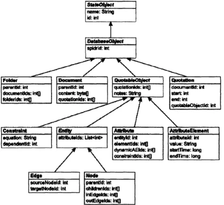
Figure 2-1 below shows the ESM class diagram.
1. 0..I ..
Qoaebc Quotaoblb ---- -- Qutin - Document
Entity Atribute AttributeElenent
..1 ..
n- Ed
Figure 2-1: The Engineering Systems Matrix models an engineering system using graph objects.
Chapter 3
The Frog Analysis Tool
For an analyst modeling a real-world system with an engineering system, the major tasks fall into three categories:
1. Collection of data
2. Organization of data into system form
3. Analysis of data
Since engineering systems are a relatively new area of research, there are few if any existing tools to assist in these tasks. Bartolomei and Sylvester recently collaborated to create a software tool, known as "Frog," designed specifically to facilitate the second and third items on the list: construction and analysis of engineering systems. Frog is based on the ESM model described earlier, and enables engineering system analysts to easily create, organize, manipulate, and view an ESM model. The Frog program is the basis on which the constraint framework described in this thesis is implemented.
3.1
System Design
3.1.1
Data Representation
Frog uses a specific data representation of the ESM. The application's ESM data model is designed in a hierarchical manner, as described by Sylvester in his Master's of Engineering thesis. Nodes in the ESM are represented as nodes in a rooted acyclic graph, also known as a tree. The key advantage to representing nodes in this hierar-chical manner is that it allows inheritance from ancestral nodes. In this hierarhierar-chical framework all attributes of a node are inherited by the node's children, and are in-herited in turn by the children of those nodes. This allows for the grouping of related components and for the abstraction of common properties in such components.
There is a single root node in every ESM, from which all other nodes are descen-dent. The root node has an attribute called "existence" that represents the node's existence. The root node itself is not a tangible component in the engineering system so its existence is undefined in that context. However, because of the inheritance property of the representation, all subsequent nodes inherit the existence attribute. Thus each node in the system has a defined period or periods of existence (according to the time-dependent properties of attributes as described earlier). Figure 3-1 shows the inheritance property of nodes.
3.1.2
Naming Conventions
In his research, Sylvester defined conventions for referring to data objects in the system. These conventions are described here.
* Nodes are specified according to their path from the root node, with the names
of nodes along the path separated by the '.' character:
[node path] = [parent path].[node name]
Node -Existence Animal -Existence -Weight -Height Human -Existence -Weight -Height -Name
Figure 3-1: An example of the inheritance property of nodes. The root node, "Node," has the attribute "Existence," which is passed down to its child "Animal." "Animal" has two more attributes, "Weight" and "Height." These two attributes, as well as the inherited "Existence" attribute, are passed down to its child, "Human."
* Relations are stated as the name of the source node followed by the '>' charac-ter, followed by the relation name, another '>' character, and finally the target node name:
[relation path] = [source node path]>[relation name]> [target node path]
e.g. node. childl>relation>node.child2
* Attributes are stated as the path of the node or relation that the attribute describes, followed by a ':' character and then the name of the attribute:
[relation path] = [owning node or relation path]:[attribute name]
e.g. node.child:attribute
Figure 3-2 below shows an example of naming conventions.
3.2
System Implementation
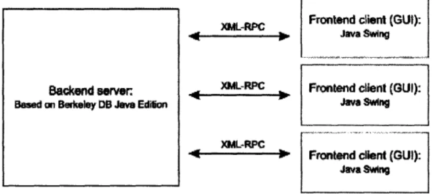
The Frog application is designed according to a client-server architecture. A single backend application serves data via the Extensible Markup - Remote Procedure Call
mammal
elephant
-weight
-age
zebra
crocodile
eats
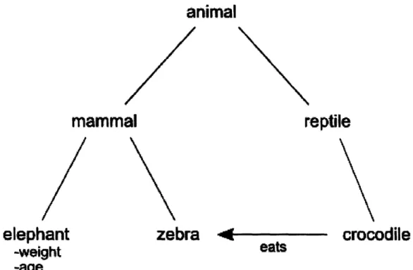
Figure 3-2: An example object model illustrating naming conventions. There are a total of 6 nodes: "animal", "mammal", "reptile", "elephant", "zebra", and "crocodile". There is an "eats" relation between "crocodile" and "ze-bra", and "elephant" has two attributes. The "elephant" node's "age" at-tribute is described as animal.reptile.crocodile:age. The "eats" relation that exists between the "crocodile" and "zebra" nodes would be described as
animal.reptile. crocodile> eats> animal. mammal. zebra.
animal
(XML-RPC) protocol to one or more remote frontend applications as shown in Figure
3-3 below. This facilitates centralized data storage and allows flexible remote access
from any PC. In addition it allows multiple users to work on the same data.
XML-RPC Frontend client (GU):
S ... .... Java Swing
Backend server XML-RPC Frontend client (GUI):
Based ao Berkeley DB Java Edilion Java Swing
XML-RPC
oI-Rf Frontend clnt (GUI): Java Swing
Figure 3-3: The Frog application has a client-server architecture. Requests are made to the server via an XML-RPC protocol.
The Frog client application is written in Java using the Swing GUI toolkit to pro-vide platform independence as well as quick prototyping and iteration. The original server application was implemented in Common Lisp using the AllegroGraph seman-tic web library by Franz, Inc [5]. However, upon further consideration, it was realized that a server implemented using AllegroGraph presented some problems:
* AllegoGraph is proprietary software and thus each machine running a Frog server would require a license from Franz.
* Each developer's machine would require a license from Franz in order to compile the Frog server.
* The client and server applications being written in two different programming languages (Java and Common Lisp, respectively) might hinder future develop-ment efforts.
Since this thesis project involved additions to the server, it was decided to re-implement the server from the ground up based on a persistent database library that would avoid the problems AllegroGraph caused. The ideal library would be reliable,
Java. Towards these goals, Oracle's Berkeley DB Java Edition [3] was chosen. Berke-ley DB is a mature open-source embeddable database library. It provides a persistent database that is reliable, and has a transaction and logging framework which allows backup and data recovery in the event of a problem. Berkeley DB is also efficient, having been proven to perform quite well on small and large datasets. Lastly, it is open-source so there are none of the licensing problems associated with AllegroGraph or other proprietary database libraries.
3.2.1
Server Architecture
The server consists of three main parts: the Spidr class, which handles ESM opera-tions, the database wrapper for Berkeley DB, and the XML-RPC server implemented using the Apache XML-RPC library [4]. In addition for each type of object in the
ESM there is a Java class for conversion between Java data and Berkeley DB records (see Appendix A for selected server source code).
The Spidr class is implemented as frog.server.Spidr. java and provides all read and write operations on the ESM data model. The Spidr class owns all model objects and manages their interaction with the environment and database.
The Berkeley DB wrapper is implemented in frog.server. SpidrEnvironment. java
and frog. server.SpidrDatabase. java. These classes provide methods for setting up,
reading and writing records on Berkeley DB databases. Common data members and
methods are stored in the abstract classes State0bject, Database0bject, Quotable0bject,
and Entity. All other data classes inherit from these abstract classes, as shown in Figure 3-4 below:
The XML-RPC server is written as frog. server. RPCServer. java and handles remote
client requests, forwarding calls onto the Spidr. It provides the following remote procedure calls:
* getSpidrso: Returns the UIDs of all ESMs.
Figure 3-4: Class structure of the Frog server data model. The abstract (non-instantiable) classes are shown in italic font. All model classes inherit data mem-bers from their parents and ancestors. For example, the Edge class inherits from its ancestors StateObject, DatabaseObject, QuoatableObject, and Entity. Thus it has the member fields name, id, spidrId, quotationIds, notes, attributelds, sourceNodeld, and targetNodeld.
given class names. Returns the UID of the new ESM.
* removeSpidr(int esmId): Deletes the specified ESM. Returns true if the re-moval succeeded.
* get (int id): Returns a String-keyed map of the relevant fields for the ESM object specified by id. If there is no such object, returns null.
* remove(int esmId, int id): Removes the specified object from the ESM spec-ified by esmId. ESM objects owned by the removed object are also removed, and ESM objects owning the removed object are updated appropriately. Returns true if the removal succeeded.
* makeNode(int esmId, String name, int parentNodeld): Creates a new child of the node specified by parentNodeId. Returns the new node's UID, or NULLID 1 if the node could not be created.
* setPosition0f(int esmId, int parentNodeId, int childNodeId, int position):
Sets the child order of a node.
* makeEdge(int esmId, String name, int sourceNodeId, int targetNodeId):
Cre-ates a new relation between the nodes specified by sourceNodeId and targetNodeId.
Returns the new relation's UID, or NULLID 1 if the relation couldn't be cre-ated.
* makeAttribute(int esmId, String name, int entityId): Creates a new at-tribute for the node or relation specified by entityId. Returns the new at-tribute's UID, or NULLID 1 if the attribute couldn't be created.
* makeAttributeElement(int esmId, int attributeId): Creates a new element
for the attribute specified by attributeId. The new attribute element will not be initialized with start and end times or a value. Returns the new element's UID, or NULLID 1 if the element couldn't be created.
'The UID NULLID is a special reserved constant that represents the ID of a non-existent data object.
* setTimelnterval(int esmId, int elementId, long startTime, long endTime):
Sets start and end times for the element specified by elementId. Returns true if the operation succeeded.
* setValue(int esmId, int elementId, String value): Sets the value for the element specified by elementId. Returns true if the operation succeeded.
* makeDocument (int esmId, String name, int folderId): Creates a new
docu-ment in the folder specified by folderId. Returns the new docudocu-ment's UID, or
NULLID ' if the document couldn't be created.
* setContents(int esmId, int docId, byte [] value): Sets the contents for the
document specified by docId. Returns true if the operation succeeded.
* getContents(int esmId, int docId): Returns the contents of the document
specified by docId.
* makeFolder(int esmId, String name, int parentId): Creates a new folder in the parent folder specified by parentId. Returns the new folder's UID, or NULL.ID 1 if the folder couldn't be created.
* makeQuotation(int esmId, int q0bjId, int docId, int start, int end):
Cre-ates a new quotation for the node, relation, attribute, or attribute element spec-ified by q0bjId in the document specified by docId. The parameters start and end indicate what part of the document the quotation references. Returns the new quotation's UID, or NULLID ' if the quotation couldn't be created.
* parse(int esmId, String query, boolean createIf NotFound): Searches for an
object in the given ESM exactly matching query. The parameter createIf NotFound
specifies if the object should be created in the case that it is not already present. Returns the UID of the object, or NULLID 1 if no matching object was found. * query(int esmId, String query): Searches for objects in the given ESM that partially match query. Returns an array of UIDs of objects that have names
containing the query. The returned array will be empty if no matching objects
Chapter 4
The Constraint Framework
The Frog analysis tool greatly assists analysts in managing and working with the datasets of complex engineering systems. However it was previously lacking in quan-titative analysis abilities. Researchers desiring to perform numerical analysis on an ESM created in Frog would need to export data to Matlab, Excel, or other mathematics-enabled programs. In these cases the Frog application was relegated to an elaborate data store. The constraint framework tackles the problem by en-abling exactly the kind of formal quantitative analysis that was previously absent from Frog. By adding mathematical relationships to ESM objects, it facilitates the modeling of natural constraints between distinct properties in an engineering system, and gives Frog a quantitative analysis ability. With the framework for constraints in place, it is possible to change values in one part of the ESM and observe the resulting changes throughout the model.
4.1
Design
The idea behind the constraint framework is to allow mathematical equations between attributes in the model. In this framework, a constraint is defined as a mathematical relationship between the values of two or more attributes. Attributes in a constraint may be dependent or independent. A valid constraint must have exactly one depen-dent attribute and one or more independepen-dent attributes, as well as a valid equation
relating these attributes.
A constraint has two important values: its equation and the dependent attribute. The equation specifies which attributes are affected by the constraint, as well as the mathematical relationship between them. The equation is defined when the constraint is created and may not be changed. This decision highlights the equation as the definitive property of the constraint; if the equation were to be altered the constraint would no longer be the same constraint. Thus the design of the framework requires that if the equation relating a set of attributes must be changed, the constraint relating them should be deleted and a new constraint created. In contrast, the single dependent attribute in the equation may be changed at any time to one of the other attributes in the equation.
Implementations of the constraint framework must be dynamic, reflecting changes in values of independent attributes by updating the values of the dependent attributes accordingly. In addition, implementations must also protect against conflicting con-straint states, which would result in attribute values being undefined. Such a state could occur if the same attribute was a dependent variable in two conflicting equa-tions, causing the attribute to have two different possible values at any given time. Another situation where a conflicting state would occur is if there was a dependency loop in the constraint framework (two or more dependent attributes that depend ei-ther directly or indirectly on each oei-ther), which would make it impossible to calculate any of the dependent values.
4.1.1 Equation Syntax
To make the constraint framework a computational framework, a well-defined syntax for defining constraint equations is needed. In order to simplify the parsing and evaluation of equations, equations are specified the same way equations are written in
Lisp syntax. There are two main differences between this equation syntax and typical mathematical syntax. The first and most notable difference is that the mathematical operator must always occur at the beginning of a statement, prior to all operands.
The parentheses also specify the grouping and order of operations. Here is a formal definition of a constraint equation:
equation := ('=' statement1 statement2),
where
statement := (operator operandi operand2
operator E {'+', '-', '*', '/', ...},
operand E statement U variable U R, and variable := '?'variableName
The current implementation in general is with repeat instances of the same variable. two-operand statements and a limited set syntax is limited to:
... operands),
not able to evaluate equations In addition, it only supports of operators, so the working
equation := ('=' statement1 statement2),
where
statement := (operator operandi operand2),
operator E {'+', '-', '*', '/'},
operand E statement U variable U R, and variable := '?'variableName
For example, the following equation written in normal math syntax:
x = 3y + 1
would be written in the Frog syntax as:
(= ?x (+ (* 3 ?y) 1))
The operands are allowed to occur in any order, thus the following two statements are equivalent:
(= ?x (+ (* 3 ?y) 1)) (= (+ 1 (* ?y 3)) ?x)
Constraint equations are defined according to this syntax, with the unique IDs of attributes serving as variables. So a constraint specifying equality between the
attributes with IDs 1041 and 1042 would be represented in the backend with the following equation:
(= ?1041 ?1042)
4.2
Implementation
The constraint framework was implemented in Java as an extension of the Frog anal-ysis application. The implementation of the constraint framework required changes to the server application as well as the client application. In the server additional model classes were added and modified, and an evaluator for constraint equations was written. In the client corresponding model changes were implemented, and a new constraint graphical user interface was added.
4.2.1
Data Representation
In order to implement the constraint framework, some changes were made to the data representation in the server. A new data class representing a constraint was added, and the attribute data class was modified to allow dynamically computed attribute elements. The constraint class stores the vital data of its equation as well as the ID of the dependent attribute. It is also possible to find the IDs of the independent
attributes by calling frog. server .model. Evaluate .getVariablelds on the equation and
then removing the dependent attribute's ID from the returned list.
Attributes were augmented to store two types of attribute elements: static and dynamic elements. Static elements are the standard user-defined attribute elements, and are always present. Dynamic elements are the elements that result from a con-straint, and are present only if it is a dependent attribute. Keeping two different lists of attribute elements preserves the static elements, which is important because attributes can switch between being dependent or independent. This happens when a constraint is created or removed, or when the dependent attribute of a constraint is switched. When the server receives a get request for an attribute, the attribute element data that is returned uses the dynamic elements if they exist, and the static
elements if there are no dynamic elements.
Each attribute also stores a list of all constraints that involve it. This is important because dependent attributes must be updated if one of the attributes they depend upon changes. When an attribute's elements are added, removed, or modified, the server recomputes the elements of the dependent attribute for each constraint involv-ing the modified attribute. This change may propagate through dependent attributes that appear as independent variables in other constraints, so the update is recursively propagated as needed through all affected attributes.
Because attributes are time-dependent, finding the dynamic elements of an at-tribute is in general a non-trivial task. For a given constraint, the value of a de-pendent attribute is only computable on the time intervals when the indede-pendent variables all have defined values. Thus the dependent attribute will have elements for all time intervals that are the intersection of the time intervals for the independent attribute's elements. The dynamic elements are determined by finding all intersecting time intervals, and then for each interval evaluating the constraint equation using the attributes' values during that interval. Each evaluation produces a new value that is paired with the time interval to create a dynamic attribute element.
Take the following example of a constraint involving one dependent attribute and two independent attributes:
(= ?1001 (+ ?1002 ?1003))
Dependent: ?1001
The constraint specifies that the value of the dependent attribute is equal to the sum of the values of the two independent attributes. Now suppose that the first independent attribute element has two elements with values 100 and 200, and that the second attribute element has two elements with values 25 and 50, as shown below:
?1002
- 01/01/07-02/01/07: 100
- 03/01/07-06/15/07: 200
- 01/15/07-04/15/07: 25
- 05/15/07-12/01/07: 50
Upon examination, it is apparent that the dependent attribute will have three attribute elements corresponding to the intersecting time periods of the independent attributes' elements, and this is how the dynamic attribute elements should be com-puted:
?1001
- 01/15/07-02/01/07: 125 - 03/01/07-04/15/07: 225
- 05/15/07-06/15/07: 250
4.2.2
Additional Server Commands
Additional database operations were also add to the Frog server application in order to provide an interface for manipulating constraints:
* makeConstraint(int esmId, String name, String equation, int dependentId):
Creates a new constraint and sets the ID of the dependent attribute. Returns its UID.
* setDependentAttribute(int esmId, int constraintId, int dependentId): Sets
which of a constraint's attributes is dependent. Returns true if the operation
succeeds.
Calling get (int constraintId) returns a String-keyed map of the constraint's data
with the following notable keys (non-interesting keys are omitted): * "equation": the equation defining the constraint
* "attributes": the IDs of all attributes related by the constraint, whether they
are dependent or independent
4.2.3
Equation Evaluator
The equation evaluator is a static class implemented as frog. server.model. Evaluate. java
(see Appendix A for source code). It is responsible for evaluating constraint equa-tions. Equations are expected to adhere to the syntax rules described earlier. The evaluator provides the following methods:
* getVariables (String expression): A utility method that parses an expression
and returns a list of the variables found in the expression. Recall that variables are denoted by the '?' character (e.g. ?x).
* getVariableIds (String expression): A utility method that parses an expres-sion and returns a list of the IDs found in the expresexpres-sion. Assumes that all variables are numerical IDs (e.g. ?2043).
* evaluate(String expression, Map<String, Double> bindings): Evaluates the given expression with the provided variable bindings. May update the bindings if the expression is an equation and contains an unbound variable (recall that an equation is an expression containing the '=' operator). The expression may contain no unbound variables if it is not an equation, and exactly one unbound variable if it is an equation.
The evaluate method is where most of the work occurs. When evaluate is called
on an expression, the evaluator first tests if the expression is a number, and if so returns that value. It then checks if the expression is a variable, and if so returns the binding of that variable. If the expression is a statement, the operands are recursively evaluated and then the operator is applied to them, giving a value.
If the expression is an equation, the unbound variable is determined by checking the bindings. Then the equation is rewritten to solve for the unbound variable. This
step is performed in the solveEquality helper method. When solving, it is sometimes
necessary to reverse operations to isolate the unbound variable. Once the equation is solved for the unbound variable, evaluate is called on the other side of the equation and the value returned is used to create a new variable binding in the bindings table.
Here is an example of an evaluator call, given the following expression and bind-ings:
(= ?5001 (/ (+ ?5002 ?5003) 2))
BINDINGS: { ?5001=5, ?5003=3}
The expression is an equation, so the evaluator checks the bindings and determines that ?5002 is the unknown variable. The equation is progressively solved for the variable ?5002: (= (- ?5002 ?5003) (* ?5001 2)) BINDINGS: { ?5001=5, ?5003=3} and then (= ?5002 (- (* ?5001 2) ?5003)) BINDINGS: { ?5001=5, ?5003=3}
The solver stops when the unknown variable is isolated, and then the other side of the equation is evaluated with the given bindings:
(- (* ?5001 2) ?5003)
BINDINGS: { ?5001=5, ?5003=3}
This returns a value of 7, and the evaluation process is completed by adding a binding to the bindings table. The method returns a value indicating success, and the caller can find the solved value of the unknown variable in the bindings table.
(= ?5002 7)
BINDINGS: {?5001=5, ?5002=7, ?5003=3}
4.2.4
Constraint Invariants
As mentioned earlier in the Design section, the implementation of the constraint framework must satisfy two key invariants in order to ensure data correctness:
* No attribute is the dependent attribute in more than one constraint (for
exam-ple x = y, x = z violates this condition if x is the dependent attribute in both
* There are no dependency loops in the constraint framework. In other words it is illegal for two attributes to either directly or indirectly depend on each other
(for example x = y + 1, y = x + 1 forms a dependency loop if x is the dependent
attribute in the first equation and y is the dependent attribute in the second equation).
The first invariant is ensured at the time of constraint creation or modification. It is relatively simple to check for the first invariant because each attribute in the model stores a list of all constraints that involve it. When a new constraint is added or there is a command to change the dependent attribute, the new dependent attribute's list of constraints is checked to make sure it is not already a dependent attribute for another constraint, and if so, the command is aborted.
The second invariant is also ensured at the time of constraint creation or modifica-tion. In order to detect dependency loops, the server considers a graph of attributes connected by constraints. It then searches this graph from the new dependent at-tribute using a depth-first search with an extended list (to prevent re-traversing the same branches more than once). If the search encounters the new dependent at-tribute again, this indicates a loop and the command is aborted. If the search does not encounter the new dependent attribute again, the invariant is satisfied and the command may safely be executed.
4.2.5
Constraint Graphical User Interface
A challenge associated with the addition of a constraint framework was creating a
user interface for creating, viewing, and editing constraints. Constraints add another level of complexity to the data model and application, and the user interface is criti-cal in managing this added complexity without overwhelming or confusing the user. For simplicity and consistency, the frontend uses the same Lisp-based equation syn-tax that the backend does, but replaces UIDs with fully qualified attribute names, enclosed by square brackets ('[' and ']'). Thus in the user interface, the constraint syntax is formally defined as:
equation := ('=' statement, statement2),
where
statement := (operator operandi operand2), operator E {'+', '-', '*', '/'},
operand E statement U variable U R, and variable := [variableName]
For example, if we defined an equality constraint between Node:attributel with ID 1041 and Node:attribute2 with ID 1042, the equation would appear in the backend and frontend in two different forms as shown below:
BACKEND: (= ?1041 ?1042)
FRONTEND: (= [Node:attributel] [Node:attribute2])
It is important to note that the evaluator in general will not work on equations with repeat instances of the same variable.
The conversion between the two representations is performed in the model class frog.model. Constraint. java (see Appendix A for source code). One side-effect of using this syntax is the addition of two new reserved characters. Since '[' and ']' have the special meaning of demarcating attribute names, they cannot be used in the names of model objects.
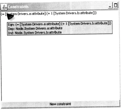
Currently the constraints for an ESM are displayed as a list of the defining equa-tions (see Figure 4-1 below), with tooltip text appearing on mouse-over to show which attributes are involved and which is the dependent attribute. Double-clicking on a constraint in the list opens a dialog for viewing the constraint and setting the de-pendent attribute. Constraints may be deleted by selecting them and pressing the DELETE key. A dialog for creating a new constraint can be shown by pressing the "New constraint" button. This list will be redesigned to give a more information-rich view of the constraints present in the system.
The more complicated design problem was the question of how users would define and edit the equations in a constraint. The design process of the user interface for defining constraints has been dynamic, with two major design choices considered. In
Figure 4-1: The constraint list user interface. The tooltip provides supplemental information including the names of the dependent and independent attributes.
both interfaces, the user enters an equation and specifies which attribute dependent. When the user presses the "Create" button, the fields are checked to ensure that they
are valid, and if so, the constraint is created.
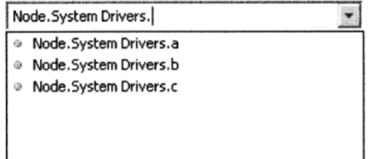
In the first design (shown in Figures 4-2 and 4-3 below) the problem is addressed by first assigning each attribute to a variable name (e.g. x, y, z) and then composing an equation from these variable names. The dependent attribute is selected by clicking one of the radio buttons to the right of the attribute names. Additional fields for variable bindings may be added by pressing the '+' button. A drop-down list in the attribute name entry fields assists the user in entering the attribute names by showing possible completions.
This design has the benefits of a succinct equation and assistance in entering attribute names. However it is not intuitive to use and it is easy for the user to enter an invalid equation by mistyping a variable name.
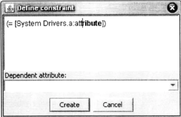
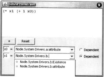
The second design (shown in Figure 4-4 below) which was ultimately chosen for use in the application simplifies the interface by having the fully qualified attribute names entered directly into the equation using square brackets to delimit attribute
(= xl (+ 1 xO))
Figure 4-2: The first interface design. The variable x0 is assigned to the attribute Node.System Drivers.a:attribute and the variable xl is assigned to Node.System Drivers.b:attribute (= xl (+ 1 xO)) = Node.System Drivers.a:attribute x = Node.System Drivers, b: Dependent Dependent :: iD ~ I ... .... ... ... ... ... . Node.System Drivers.b:Existence Node.System Drivers.b:attribute
Figure 4-3: The first interface design. A drop-down list box assists users in entering attribute names.
::::::gZ : :: :: : : >---t <T v: :U:::::: L , , : ::::Z Z
-li-names from the rest of the mathematical symbols. The dependent attribute is selected via a dropdown list box populated according to the attribute names parsed from the equation.
(= [System Drivers.a:attribute] (+ 1 [System Drivers.b~attribute]))
Diodn atrbut.
~ivers. D~ri uers])at
System Drivers. b: attribute
Figure 4-4: The second interface design. The user enters fully qualified attribute names directly into the equation, demarcated by square braces ('[' and ']'). The dependent attribute is selected from a drop-down list.
In order to simplify the entry of constraint equations, the equation area provides input assistance. There is an auto-complete feature that assists the user in entering attribute names by showing (in bold) the next possible completion for the name the user is typing. Pressing the TAB key will fill in the rest of the name with the auto-complete suggestion. Figures 4-5, 4-6, and 4-7 show the auto-complete function in action. In addition, when an open parenthesis or brace ('(' or '[') is typed, the matching closing parenthesis or brace (')' or ']', respectively) is automatically inserted so the user doesn't need to type it. These closing characters are also deleted if the matching open character is deleted.
The main weakness of the second interface design is that since all variable def-initions are performed in a text entry area, there is no drop-down list of possible completions when entering an attribute name. This forces the user to recall the names of attributes that will be part of the constraint rather than just choosing them out of a list. Although the user receives assistance via the auto-complete feature, it is still desirable to show all (or at least several) possible completions instead of just one. It is likely that this issue can be addressed through additional development of a customized text area as is described in the Future Work section.
Figure 4-5: The second interface design showing auto-complete assistance. When the user begins typing a name, the next possible completion is shown in bold font.
Figure 4-6: The second the TAB key fills in the
interface design showing auto-complete assistance. Pressing rest of the name with the auto-complete suggestion.
Figure 4-7: The second interface design showing auto-complete assistance. The user may then continue to enter the rest of the fully qualified attribute name with auto-complete assistance. (= [Systeml Drivers]) Dependent attribute: Cte Cancel (= [System Driversi) Dependent attribute: Create Cancel
Even with the issue faced by the second interface, it was determined that its advantages of being more intuitive and less confusing outweighed the negatives, and so it was chosen over the first design. See Appendix B for the current source code of the GUI components described here.
Chapter 5
Conclusion
5.1
Contributions
The work presented here extends the Frog analysis tool and adds a mathematical capability to the Engineering Systems Matrix model. The constraint framework that was designed in this thesis gives new capabilities to the ESM, allowing equations to relate different attribute values in the ESM, adding a new dimension to engineer-ing system analysis. The framework was implemented as an addition to the Frog analysis tool and provides a rich user interface for viewing, creating, editing, and deleting constraints from the system model. This implementation is written in Java and uses the Oracle Berkeley DB and Apache XML-RPC libraries. The extended Frog application allows analysts to perform more complex analysis while simplifying data management. In summary, the mathematical and relational capability this new constraint framework provides gives users more powerful analysis options.
5.2
Known Issues
The following is a list of known issues in the implementation of the constraint frame-work. These issues should be addressed during future development of the frameframe-work. * The constraint-enhanced database model is not backwards-compatible because it introduces the new reserved symbols '[' and ']' (which join the already
re-served symbols '<' and '>'). Because of this it is conceivable that older ESMs
imported into the new application may have improperly named objects. This could be solved by pre-processing old databases and adding an escape character to reserved symbols (this has the drawback of introducing another reserved sym-bol). The constraint framework also requires new XML-RPC methods. This means that the new client will not work correctly with previous versions of the server (old client versions will work with the new server but will not be able to use constraints).
* The export function in the frontend is not set up for handling constraints, so constraints will not be persisted to exported ESMs. The export function will need to be updated to include constraints in its output files.
* The evaluator is not able to evaluate equations with repeated instances of the dependent attribute, for example (= (+ ?x ?x) 6) can not be evaluated. A more powerful evaluator would be desirable to allow analysts to enter a larger variety of equations.
5.3
Future Work
There are a number of logical extensions and improvements that can be built upon the work presented here, both in the user interface and in the framework itself.
The constraint framework provides flexibility and power to analysts, and the client application needs a full-featured user interface to take advantage of it. When creat-ing a constraint, specifycreat-ing equations can be a troublesome task if the user doesn't remember the full names of the attributes involved. It would reduce cognitive load on the user if the GUI provided a contextual drop-down list of possible completions (similar to the search box shown in Figure 5-1 below) to assist users when entering attribute names.
In order to assist the user in managing a highly-constrained system with many inter-related attributes, I propose the addition of new views to the GUI. A table view
Figure 5-1: The search box provides a drop-down list of possible completions when entering names in the document coding editor.
similar to the ESM table view (shown in Figure 5-2 below) could give an immediate overview of how attributes in the model are co-constrained.
A graph view with attributes as the nodes in the graph and constraints as the edges in the graph would allow the analyst to see on a high level which attributes affect others the most. Dependent and independent attributes could be shown in different colors to distinguish between them. To add to this view, partial derivatives could be calculated to find how changes in an attribute's value affected neighboring attributes, and the chain rule applied to see the attribute's influence on further away attributes. These strengths of influence could be represented by thicker or thinner edges connecting attribute nodes. In this way it would be easy to determine which attributes in the graph are the most important in terms of influence.
In the backend the expression evaluator can be made more powerful and flexible. Adding more operator and variable types would allow a wider variety of equations. Boolean support would allow for interesting computation possibilities. A scripting language for plug-in functions is another possible way to expand the evaluator. This would allow functions to be defined by the user and included in constraint equations. To use such a scripting language the user would need to provide the definition of the function as well as its inverse so equations involving the scripted function could be solved in the evaluator.
Node.System Drivers,
a Node.System Drivers.a
a Node.System Drivers.b Node.System Drivers.c
Wl! L ii >'i : :: .. 1E=: ur:- L ., > i UJL> ii ii i i : " i; "I EE u -. -. i: " . . . ! .. . -D u'UE) %A .IC kA A kAr.. : 1 0 . A 0 k L .I-> CL 71 0 a .. il (U 7D 0 .> a) > U 'D0-ircr 3:ilt -r- i-' z, U
-Jewellery and pre
Leather products Construction mate Biopharmaceutical Agricultural produ Power generation Prefabricated enc
Lghting and electr
Aerospace vehicle
Oil and gas produ Medical devices
. Furniture Forest products
Figure 5-2: The ESM view allows users to see which nodes are related to each other.
Appendix A
Selected server source code
A.1
Spidr.java
public class Spidr {
// public static final int ROOT_NODE_ID - 1000;
public static final int NULL_ID - -1;
// IDs to return when there is a problem creating or editing constraints public static final int ATTALREADYDEP_ERRORID - -2; // The attribute is
// already dependent
public static final int CYCLE_ERROR_ID - -3; // There is a dependency
// cycle
public static final int SPIDR_LIST_ID - 0;
private Environment environment;
// The main database private SpidrDatabase db; private IdFactory idFactory;
private Transaction currentTxn - null;
public Spidr(Environment env, Database objectDb, Database classDb, SecondaryDatabase namesDb, Database idDatabase) {
this.environment = env;
db = new SpidrDatabase(objectDb, classDb, namesDb); idFactory - new IdFactory(idDatabase);
try {
if (get(SPIDR.LIST_ID) -- null) {
createSpidrList();
}
} catch (DatabaseException e) {}
private int getNextId() {
return idFactory.nextId(currentTxn);
}
public SpidrList getSpidrList() throws DatabaseException {
private Node createRootNode(int spidrld) throws DatabaseException {
Node root = new Node(NULLID, "Node", getNextId(), spidrld);
// Update the database
db.newRecord(currentTxn, root.writeKeyO, root.writeClassO, root .writeEntryO);
createAttribute(root.getIdO, "Existence", true);
return root;
}
private Folder createRootFolder(int spidrld) throws DatabaseException {
Folder root = new Folder(NULL_ID, "Folder", getNextIdO), spidrId);
// Update the database
db.newRecord(currentTxn, root.writeKeyO, root.writeClassO), root .writeEntryO);
return root;
// Returns the DatabaseDbject for the specified ID, or null if it isn't
// found
public StateObject get(int id) throws DatabaseException {
if (id == NULL_ID) { return null; I
DatabaseEntry key = StateObject.writeKey(id); return get(key);
// Returns the DatabaseObject for the specified key, or null if it isn't // found
private StateObject get(DatabaseEntry key) throws DatabaseException {
DatabaseEntry classEntry -new DatabaseEntryO; DatabaseEntry objEntry - new DatabaseEntryO;
OperationStatus status = db.get(currentTxn, key, classEntry, objEntry); if (!status.equals(OperationStatus.SUCCESS)) return null;
Tuplelnput in = new Tuplelnput(classEntry.getDataO); String className = in.readStringo);
StateObject obj;
if (className.equals(Attribute.class.getNameO)) {
obj - new AttributeO);
} else if (className.equals(Constraint.class.getNameO)) {
obj = new Constraint();
} else if (className.equals(AttributeElement.class.getNameO)) {
obj = new AttributeElementO;
} else if (className.equals(Document.class.getNameO)) {
obj - new DocumentO);
} else if (className.equals(Edge.class.getName())) {
obj - new Edge();
} else if (className.equals(Folder.class.getNameO)) {
obj = new FolderO);
} else if (className.equals(Node.class.getNameO)) {
obj = new Node();
I else if (className.equals(Quotation.class.getName))
obj = new QuotationO;
} else if (className.equals(SpidrList.class.getNameO)) {
obj = new SpidrListO;
} else if (className.equals(SpidrObject.class.getNameO)) {
} else {
return null;
}
obj .readEntry(objEntry); return obj;
// Search for a node, relation, or attribute name in the database public List<Databasebject> query(int spidrId, String queryString)
throws DatabaseException {
List<Databasebject> objectList = new ArrayList<DatabaseObject>() ; SpidrObject spidr0bj - (SpidrObject) get(spidrld);
Node rootNode - (Node) get(spidrObj.getRootNodeldO);
// Check to make sure the name is prepended by the root node name
if (queryString.index0f(rootNode.getShortNameO) !- 0) { queryString - rootNode.getNameO + Node.NODE.DELIMITER
+ queryString;
}
// Check if it's an attribute String[] attributeSplit - queryString
.split (Attribute.ATTRIBUTE_DELIMITER); if (attributeSplit.length -- 1
Ak queryString.contains(Attribute.ATTRIBUTEDELIMITER)) {
Entity entity - (Entity) parse(spidrId, attributeSplit[0, false);
if (entity !- null) {
for (Integer id : entity.getAttributeIds()) {
objectList.add((Attribute) get(id));
} }
} else if (attributeSplit.length -= 2) {
Entity entity - (Entity) parse(spidrId, attributeSplit0WO, false); if (entity != null) {
for (Integer id : entity.getAttributeldsO) {
Attribute attribute - (Attribute) get(id);
if (attribute.getShortName(). contains(attributeSplit(1])) {
objectList .add(attribute);
} }
return objectList;
// Check if it's an edge
String[] edgeSplit - queryString.split(Edge.EDGE_DELIMITER); int edIndex - queryString.indexOf (Edge.EDGEDELIMITER); if (edgeSplit.length -- 3) {
// source>edgeName>target: query on the node
return query(spidrId, edgeSplit[23);
} else if (edIndex !- -1) { // source>edgeName
Node source - (Node) parse(spidrld, edgeSplit[l0, false); if (source !Inull) {
for (Integer id : source.getOutEdgeldsO) {
Edge edge - (Edge) get(id);
if (edge.getShortName() .contains( queryString.substring(edIndex + 1))) {
I
return objectList;
// Check if it's a node
int ndIndex = queryString.lastIndex0f(Node.NODE_DELIMITER); if (ndIndex !- -1) {
Node parent = (Node) parse(spidrId, queryString.substring(0, ndIndex), false);
if (parent !- null) {
for (Integer id : parent.getChildIdsO()) { Node child = (Node) get(id); if (child.getShortName().contains(
queryString.substring(ndIndex + i))) { objectList.add(child);
}
return objectList;
public DatabaseObject parse(int spidrId, String name, boolean createIfNotFound) throws DatabaseException { try {
SpidrObject spidrObj - (SpidrObject) get(spidrId); Node rootNode = (Node) get(spidrObj.getRootNodeIdO);
// Check to make sure the name is prepended by the root node name
if (name.index0f(rootNode.getShortName()) !- 0) { name - rootNode.getNameO) + Node.NODE_DELIMITER + name;
}
DatabaseEntry nameKey - new DatabaseEntry(name.getBytes("UTF-8")); List<DatabaseEntry> candidateKeys = db.getInSecondary(currentTxn.
nameKey);
for (DatabaseEntry keyEntry : candidateKeys) { StateObject so - get(keyEntry);
if (so instanceof DatabaseObject) { DatabaseObject dObj - (DatabaseObject) so; if (dObj.getSpidrld() == spidrld) { return dObj; I
}
if (createIfNotFound) { // Check if it's an attribute String[] attributeSplit = name
.split(Attribute.ATTRIBUTE_DELIMITER); if (attributeSplit.length == 2) {
Entity entity = (Entity) parse(spidrld, attributeSplit[03, false); if (entity != null) { return createAttribute(entity.getIdO(), attributeSplit [1); } else { return null;
// Check if it's an edge
String[] edgeSplit - name.split(Edge.EDGEDELIMITER); if (edgeSplit.length -- 3) {
Node source - (Node) parse(spidrId, edgeSplitO],. false); Node target - (Node) parse(spidrId, edgeSplit[23, false);
if ((source != null) && (target != null)) {
return createEdge(source.getId(), target.getIdO(). edgeSplit [1J);
} else {
return null; }
}
// Check if it's a node
int ndIndex - name.lastIndex0f (Node.NODE_DELIMITER);
if (ndIndex !- -1) {
Node parent - (Node) parse(spidrId, name.substring(0, ndIndex), false);
if (parent !- null) {
return createNode(parent.getIdO), name .substring(ndIndex + 1)); } else { return null; } // Can't parse it return null; } else { return null; }
I catch (UnsupportedEncodingException willNever0ccur) {
return null;
}
public boolean setPositionOf(int spidrId, int parentId, int childId, int position) throws DatabaseException {
Node parent - (Node) get(parentId); if (parent - null) {
return false;
} else if (parent.setPositionf(childId, position)) {
update(parent); return true;
} else {
return false; }
public boolean setDependentAttribute(int constraintId, int dependentAttributeld) throws DatabaseException {
StateObject sObj - get(constraintId);
if (!(sObj instanceof Constraint)) { return false; I
Constraint con - (Constraint) sObj;
Attribute dependent = (Attribute) get(dependentAttributeld);
if (dependent -- null) {
return false;
} else if (dependent.isDependentAttributeO) {
// it is already a dependent attribute // System.out.println("Already dependent");


![Figure 4-4: The second interface design. The user enters fully qualified attribute names directly into the equation, demarcated by square braces ('[' and ']')](https://thumb-eu.123doks.com/thumbv2/123doknet/14460837.520417/39.918.316.605.241.431/figure-second-interface-qualified-attribute-directly-equation-demarcated.webp)