HAL Id: hal-01402742
https://hal.archives-ouvertes.fr/hal-01402742
Submitted on 25 Nov 2016
HAL is a multi-disciplinary open access
archive for the deposit and dissemination of
sci-entific research documents, whether they are
pub-lished or not. The documents may come from
teaching and research institutions in France or
abroad, or from public or private research centers.
L’archive ouverte pluridisciplinaire HAL, est
destinée au dépôt et à la diffusion de documents
scientifiques de niveau recherche, publiés ou non,
émanant des établissements d’enseignement et de
recherche français ou étrangers, des laboratoires
publics ou privés.
Common Pattern Modeling Language for Object and
Component Architectures
Jacob Geisel, Brahim Hamid, Adel Ziani, Ansgar Radermacher
To cite this version:
Jacob Geisel, Brahim Hamid, Adel Ziani, Ansgar Radermacher. Common Pattern Modeling Language
for Object and Component Architectures. 20th Pattern Languages of Programs Conference (PLoP
2013), Oct 2013, Monticello, Illinois, United States. pp. 1-16. �hal-01402742�
O
pen
A
rchive
T
OULOUSE
A
rchive
O
uverte (
OATAO
)
OATAO is an open access repository that collects the work of Toulouse researchers and
makes it freely available over the web where possible.
This is an author-deposited version published in :
http://oatao.univ-toulouse.fr/
Eprints ID : 15155
The contribution was presented at PLoP 2013:
http://www.hillside.net/plop/2013/
To cite this version :
Geisel, Jacob and Hamid, Brahim and Ziani, Adel and
Radermacher, Ansgar Common Pattern Modeling Language for Object and
Component Architectures. (2013) In: 20th Pattern Languages of Programs
Conference (PLoP 2013), 23 October 2013 - 26 October 2013 (Monticello,
IL, United States).
Any correspondence concerning this service should be sent to the repository
administrator:
[email protected]
Common Pattern Modeling Language for Object and Component
Architectures
Jacob Geisel, IRIT, University of Toulouse, France Brahim Hamid, IRIT, University of Toulouse, France Adel Ziani, IRIT, University of Toulouse, France Ansgar Rademacher, CEA-LIST, France
Design patterns are widely used as a meaning to capture and provide valuable expert information in order to describe a solution for a given problem or to provide a selected property. By choosing one or more patterns and applying them during the software development life cycle, software engineers are able to use proven building blocks for achieving software on a large scale. In our work, we deal with a pattern modeling language as a new representation of patterns to ease their application and categorization in software engineering. In this paper, we demonstrate the capabilities of our pattern modeling language for software architectures. For that, we propose a framework based on a process with patterns within a set of model transformation rules to target object and component architectures. This leads to a simple way to model patterns for reuse independently from the targeted system-under-development’s architecture. To illustrate the approach we consider an example of a secure communication pattern.
1. INTRODUCTION
Recent times have seen a paradigm shift in terms of design through the combination of multiple software engineering paradigms e.g. Component-based Software Engineering (CBSE), Model-Driven Engineering (MDE) and Patterns. This paradigm shift is changing the way systems are developed, reducing development time significantly. Embedded systems are a case, where a range of products for assorted domains such as energy, transportation, automotive, and so on are conceived as a family. Embedded systems solutions are expected to be efficient, flexible, reusable on rapidly evolving hardware and of course at low cost [Zurawski 2007]. However, most of the solutions tend to be concrete and for a specific, single, domain (avionics, automotive, transports and energy).
MDE [Schmidt 2006] provides a very useful contribution for the design of embedded systems, since it bridges the gap between design issues and implementation concerns. It helps the designer to specify in a separate way functional and non-functional requirement issues at a high level, which is important to guide the implementation process. Of course, an MDE approach is not sufficient by itself, but does offer an ideal development context. MDE frameworks may help software engineering specialists in their tasks, but indeed it would be interesting to provide
(partial) solutions and to guide them fulfilling recurring requirements. In software engineering, Pattern meets this need. We leverage on this idea to propose a novel common pattern modeling language.
The desired role when using patterns is to ease, systematize and standardize the approach to the construction of software based systems. Most of the software architectures for large and complex systems have used patterns. However, the problem consists in identifying them explicitly for reuse. This leads to the necessity to propose common pattern representation models targeting widely used modeling approaches (e.g. component-based, object oriented, etc.).
In our previous works [Hamid et al. 2011], we proposed methods to model Security and Dependability (S&D) aspects in pattern. A metamodel is serving as a common language for describing patterns. This metamodel deeply refines the GoF pattern representation [Gamma et al. 1995] to fit with Security, Dependability and Resource properties. This yields simplifications and enhancements of some pattern-based process development activities such as search and selection of patterns according to targeted properties. The patterns are modeled independently from target development application platforms. In this paper, we propose to use MDE, and particularly model transformation techniques, allowing patterns to be adapted and used in different modeling environments (e.g. General Purpose Modeling and Domain Specific Languages). A set of Security and Dependability patterns is organized as a pattern system and stored in a repository within the SEMCO (for System and software Engineering for embedded systems applications with Multi-Concerns) platform1. The pattern’s instantiation, from the repository into the developer’s modeling environment, uses the aforementioned transformations.
The work presented is this paper is conducted in the context of a project called SEMCO. SEMCO builds on a theory and novel methods based on a repository of models and patterns which (1) promote engineering separation of concerns, (2) supports multi-concerns, (3) use patterns to embed solutions of engineering concerns and (4) supports multi-domain specific process. This project is three-fold: providing a repository of modeling artifacts, tools to manage these artifacts and guidelines to build complete engineering systems.
1.1 Background & Previous Works
In this section, we introduce the context, an overview of connected works, a set of mechanisms and tools that will be useful in understanding our approach.
Model-Driven Engineering. MDE promotes models as first class elements. A model can be represented at
different levels of abstraction and the MDE vision is based on (1) the metamodeling techniques to describe these models and (2) the mechanisms to specify the relations between them. Model exchange is at the heart of the MDE methodology as well as the transformation/refinement relation between two models.
A model transformation specifies mechanisms to automatically create target models from source models. The Object Management Group (OMG) defines a model transformation as: the process of converting a model into
another model of the same system [Miller and Mukerji 2003]. Similarly, [Kleppe et al. 2003] defines model
transformation as the automatic generation of a target model from a source model, according to a transformation
description.
The Meta Object Facility (MOF) [OMG 2006] is a standard defined by the OMG to describe modeling languages such as the Unified Modeling Language (UML) [OMG 2009]. Query View Transformation (QVT) [OMG 2008], based on the Object Constraint Language (OCL) [OMG 2010], is an OMG standard to specify model transformations in a formal way, between metamodels conforming to MOF.
Domain Specific Modeling Language. A language is defined by an abstract syntax, a concrete syntax and the
description of semantics [France and Rumpe 2005; Kleppe 2007; Harel and Rumpe 2000]. The abstract syntax defines the concepts and their relationships which is often designed by a metamodel. On the one hand, the concrete syntax defines the appearance of the language. In this way, a grammar or regular expressions is most of the time
used to design this one. On the other hand, semantics define the sense and meaning of the structure by defining sets of rules.
Domain Specific Modeling (DSM) in software engineering is used as a methodology using models as first class citizens to specify applications within a particular domain. The purpose of DSM is to raise the level of abstraction by only using the concepts of the domain and hiding low level implementation details [Gray et al. 2007]. A Domain Specific Language (DSL) typically defines concepts and rules of the domain using a metamodel for the abstract syntax, and a concrete syntax (graphical or textual). DSLs allow to specify systems in a domain-friendly manner. As we shall see, processes in Domain Specific Modeling reuse a lot of practices from Model-Driven Engineering, for instance, metamodeling and transformation techniques.
There are several DSM environments, one of them being the open-source Eclipse Modeling Framework (EMF) [Steinberg et al. 2009]. EMF provides an implementation of EMOF (Essential MOF), a subset of MOF, called Ecore2. EMF offers a set of tools to specify metamodels in Ecore and to generate other representations of them, for instance Java.
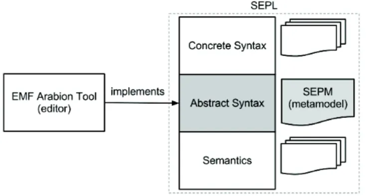
Pattern Modeling Language. SEPL (System and software Engineering Pattern modeling Language) as depicted
in Figure 1 is the pattern modeling language defined in SEMCO, where SEPM (System and software Engineering Patten Metamodel – see Section 2) represents the abstract syntax of this language. In this paper we consider only the abstract syntax. SEPM is based on previous works [Hamid et al. 2011] in which we associate MDE and formal validation to build Security and Dependability (S&D) patterns for trusted Resource Constrained Embedded System (RCES) applications3. We also provided an editor (Arabion), based on the EMF technology, to edit S&D patterns with resource properties and constraints. Arabion is a tree-based editor which is implements SEPL’s abstract syntax.
Fig. 1. System and software Engineering Pattern modeling Language: SEPL
1.2 Intended Contributions
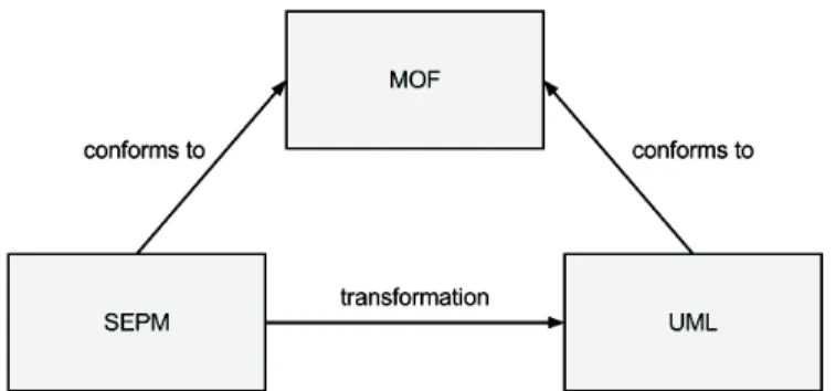
Operational QVT allows to describe derivation rules between two metamodels conforming to the MOF such as the UML metamodel. We begin with Fig. 2 to highlight the relationships between MOF, UML and SEPM. Here, we specify our pattern modeling language (SEPM) using the Meta Object Facility (MOF) constructs. These
2Ecore is a meta-metamodel 3http://www.teresa-project.org/
Fig. 2. SEPM, MOF and UML Relatioships
Fig. 3. Conceptual View of Pattern
relationship between MOF and the SEPM metamodel are used to master the mapping towards UML concepts in object and component software design.
The contribution of this work is threefold:
—A specification of the SEPM using the MOF constructs.
—Automation for pattern reuse: we propose an MDE framework to target both object and component architectures. —Apply in practice to an Security Pattern.
1.3 Paper Organization
This paper is organized as follows. Section 2 presents the SEPM metamodel to describe patterns using MOF constructs. Section 3 and Section 4 deal with the mapping between SEPM and the object & component UML metamodels respectively. Then, in Section 5 we illustrate the approach by the example of the secure communication pattern. Section 6 discusses the state of the art of pattern modeling languages that address pattern in UML. The last Section concludes this work with a synthesis and gives an overview of future work.
2. SYSTEM AND SOFTWARE ENGINEERING PATTERN METAMODEL(SEPM)
In this Section, we present SEPM as a set of concepts needed to specify a pattern. At the end of this Section, we try to point out the most important concepts involved in our illustrating example.
2.1 Metamodel Concepts
The conceptual view of pattern as we proposed in [Hamid et al. 2011] is shown in Fig. 3, provides a clear and flexible structure. SEPM describes all the concepts (and their relations) needed to represent patterns in the context of system and software applications. In SEPM, we deeply refined the GoF pattern representation [Gamma et al. 1995] to fit with Security, Dependability and Resource properties. In addition the proposed representation takes into account the simplification and the enhancement of some pattern-based process development activities. These enhancements are mainly search and selection of patterns according to targeted properties.
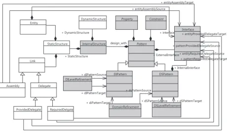
Fig. 4. System and software Engineering Patten Metamodel: SEPM
The principal classes of the metamodel are described with UML notations in Figure 4. In the following, we present in more details the meaning of principal concepts of SEPM. We will use DI to refer to domain independent and DS to refer to domain specific.
—Pattern. This block represents a modular part of a system that encapsulates a solution of a recurrent problem. A Pattern defines its behavior in terms of provided and required interfaces. As such, a Pattern serves as a type whose conformance is defined by these provided and required interfaces.
—DIPattern. Inherits from Pattern. A DIPattern may be manifested by one or more artifacts, and in turn, that artifact may be deployed by its execution environment. This is the key entry artifact to model pattern at domain independent level. A DIPattern can be refined from another DIPattern. We call this relation: DILevelRefinement. —Interface. Pattern interacts with its environment through Interfaces which are composed of operations. A provided interface is implemented by the Pattern and highlights the services exposed to the environment. A required interface corresponds to services needed by the pattern to work properly. So, larger pieces of a system’s functionality may be assembled by reusing patterns as parts in an encompassing pattern or assembly of patterns, and wiring together required and provided interfaces. Finally, we consider two kinds of interfaces: External interfaces allow implementing interaction with regard to the integration of a pattern into an application model or to compose patterns. Internal interfaces allow implementing interaction with the platform. At a low abstraction
level it is e.g. possible to define links with a software or hardware module for the cryptographic key management. These interfaces are realized by the DSPattern. Note that an DIPattern does not have an InternalInterface. —Property. Is a particular characteristic of a pattern. A Property is either an S&D Property or an RCES Property.
Each property of a pattern will be validated at the time of the pattern validating process and the assumptions used will be compiled as a set of constraints which will have to be satisfied by the domain application. —Internal Structure. Constitutes the implementation of the solution proposed by the pattern. Thus the
Internal-Structure can be considered as a white box which exposes the details of a pattern. In order to capture all the key
elements of the solution, the Internal Structure is composed of two kinds of Structure: static and dynamic. Note that a pattern can have several possible implementations. The Static Structure is composed of Entity and Link. —Entity. Constitutes the basic element of the Static Structure.
—Link. Constitutes the basic link of the Static Structure. SEPM takes into account two kinds of specific Links:
Assembly and Delegate. Assembly is a basic connection between two Entities and Delegate is a connection
between the Pattern and an Entity.
—DSPattern. Inherits from Pattern. It is used to build a pattern at DS. Furthermore a DSPattern has Internal Interfaces in order to interact with the domain specific platform. This is the key entry artifact to model pattern at domain specific level. On a one hand, a DSPattern can be built starting from an existing DIPattern. We call this relation: DomainRefinement. On another hand, a DSPattern can be refined from another DSPattern. We call this relation: DSLevelRefinement.
2.2 SEPM Concepts to be Mapped
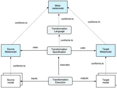
The overview of the framework’s transformations is shown in Fig. 5. The concepts of the transformations are expressed (i.e. Transformation Specification) using the Source Metamodel(s) and the Target Metamodel(s). Once specified, transformation is run (i.e. Transformation execution) taking as input the Source Model(s) and producing as output the Target model(s).
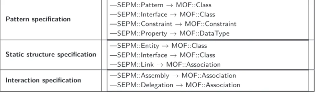
Pattern specification
—SEPM::Pattern → MOF::Class —SEPM::Interface → MOF::Class —SEPM::Constraint → MOF::Constraint —SEPM::Property → MOF::DataType
Static structure specification
—SEPM::Entity → MOF::Class —SEPM::Interface → MOF::Class —SEPM::Link → MOF::Association
Interaction specification —SEPM::Assembly → MOF::Association
—SEPM::Delegation → MOF::Association
Fig. 6. SEPM Concepts (→ means instance of )
Now we propose a synthesis of the concepts of SEPM (Source Metamodel) involved in the mapping towards the UML (Target Metamodel) concepts. In addition, we present the specification we propose to represent these using MOF (Meta-metamodel) constructs (see Fig. 6). The transformation rules are expressed using QVT (Transformation Language) at the metamodel level to be applied at the model level. An illustration on a concrete example is given in Section 5.
We use Ecore rather than the MOF since we use EMF to implement SPEM, UML and the transformation rules. Note, however, that our vision is not limited to the EMF platform.
In the next sections, we propose a process based on a set of transformation rules to encode the mapping between SEPM and UML models.
3. SEPM TOWARDS UML OBJECT MODEL
Following the modeling process, as depicted in Fig. 7, and the UML Object metamodel we define a one-to-one mapping between the SEPM concepts and the UML object concepts as shown in Fig. 3.
Fig. 8. SEPM to UML Object Mapping
SEPM Concepts UML Object Concepts
Pattern Class
Entity Class
Pattern Provided External Interface Interface Pattern Required External Interface Attribute Pattern Required Internal Interface Static Variable Constraint OCL Constraint Static Internal Structure of a Pattern Class Diagram Dynamic Internal Structure of a Pattern Sequence Diagram Required External Interface of an Entity Attribute Required Internal Interface of an Entity Attribute
Property DataType
Binding of type Delegation Link toward the appropriate wrapper Binding of type Assembly Variable affectation
After the presentation of the basic concepts (see Fig. 3), we need to further clarify the pattern artifacts, for example, external and internal interfaces. A provided external interface of a pattern is represented by an interface which is realized by the class representing the pattern. In addition, a class is added in order to play the role of a wrapper. Indeed, this representation allows to manage the link between the pattern and the entities representing the internal structure.
A required external interface of a pattern is represented by an attribute within the class representing the pattern. In the same way, a required external interface of a pattern is represented by a class to play the role of a wrapper. A required internal interface of a pattern refers to a library provided by the platform through an attribute.
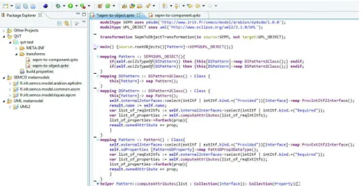
Fig. 9 shows an overview of a set of transformation rules using QVT under EMF. SEPM and UML_OBJECT4 are specified using Ecore and act, respectively, as source and target metamodel for the transformation rules.
Fig. 9. Mapping Rules from SEPM Concepts to UML Object Concepts using QVT
4. SEPM TOWARDS UML COMPONENT MODEL
As in the previous Section, we define a one-to-one mapping between the SEPM concepts and the UML component concepts as shown in Fig. 10. Fig. 4 presents the mapping we propose. In a similar way to the UML object, we need to further clarify the pattern artifacts.
Fig. 10. SEPM to UML Component Transformation
A Pattern is represented by a complex component (i.e. composite). The mapping between a Pattern and a Component is a logical choice because our pattern vision is already done on the component concept. The diagram of representation is the Component diagram / Composite structure.
An Entity is represented by a Basic Component. In the UML superstructure v2.1.0 the Basic Components package defines the concept of a component as a specialized class that has an external specification in the form of one or more provided and required interfaces, and an internal implementation consisting of one or more classifiers.
Fig. 11. SEPM to UML Component Mapping
SEPM Concepts UML Component Concepts
Pattern Complex Component
Entity Basic Component
Interfaces of a Pattern Ports/Interfaces Interfaces of an entity Interfaces (Provided/Required) Constraint OCL Constraint
Property DataType
Static Internal Structure of a Pattern Internal Structure of a Complex Component Dynamic Internal Structure of a Pattern Sequence Diagram
Binding of type Delegation Delegation Connector Binding of type Assembly Assembly Connector
Interfaces of a pattern are represented by Ports/Interfaces (provided/required). In UML superstructure v2.1.0 a Port may specify the services a classifier provides (offers) to its environment as well as the services that a classifier
expects (requires) of its environment. We can use two ports: the first one to gather all the external interfaces and the second one to gather all the internal interface.
Interfaces of an entity are represented by Interfaces (provided/required). In UML superstructure v2.1.0 a Basic
Component has a number of provided and required Interfaces, that form the basis for wiring components together.
Properties of a pattern are represented by DataTypes. In UML superstructure v2.1.0 when a property is owned
by a classifier other than an association via ownedAttribute, then it represents an attribute of the class or data type.
Static Internal Structure of a pattern is represented by the Internal Structure of a complex component (i.e.
assembly of Basic Component). The diagram of representation is the Component diagram / Composite structure.
Binding of type Delegation (in the pattern context) is represented by a Delegation Connector. In UML
superstructure v2.1.0 delegation connectors are used to model the hierarchical decomposition of behavior, where services provided by a component may ultimately be realized by one that is nested multiple levels deep within it.
Binding of type Assembly (in the pattern context) is represented by an Assembly Connector. In UML
superstruc-ture v2.1.0 an assembly connector is a connector that is defined from a required interface or port to a provided interface or port.
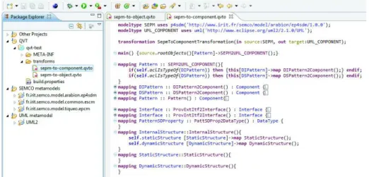
Fig. 12 shows an overview of a set of transformation rules using QVT under EMF. SEPM and UML_COMPONENT5 are specified using Ecore and act, respectively, as source and target metamodel for the transformation rules.
Fig. 12. Mapping rules from SEPM concepts to UML Component Concepts using QVT
5. ILLUSTRATING EXAMPLE: SECURE COMMUNICATION PATTERN
In this section we propose to demonstrate our approach through an illustrating example: secure communication pattern. Messages passing across any public network can be intercepted. The problem is how to ensure that the data is secure in transit, e.g. how to guarantee security properties (e.g.. data authenticity). This is one of the goals of the secure communication pattern. However, for reasons of clarity, we focus on the secure communication
pattern independently from the application domain. We begin with the its common model representation built with the Arabion tool.
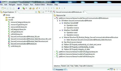
Fig. 13. Secure Communication Pattern: Arabion View
5.1 SEPM Representation: Common Model
Arabion offers the possibility to capture the specifications of the pattern (black box view) and the details of its solution (white box view) with SEPM. The internal structure is being designed using UML tools, in our case we use the open-source UML tool Papyrus6.
The specification of the secure communication pattern, as depicted in Fig. 13, guarantees three kinds of properties: authenticity, confidentiality and integrity. In addition, the pattern exposes two external interfaces:
ServerExtItf and ClientExtItf . Fig. 14 shows the static structure of the secure communication using the UML composite structure with Papyrus tool. The elements that compose the static structure are the following: a Client and a Server exchanging data, mechanisms such as: KeyExchangeM echanism, EncryptionM echanism,
SharedEncryptionKey. Furthermore two delegation links are expressed between: the Pattern and the Server, and between the Pattern and the Client.
5.2 Object Architecture
Fig. 15 depicts the secure communication pattern for object architecture. In other words, the expected results from our transformation engine.
Fig. 15. Secure Communication Pattern: Object View
Fig. 5.2 describes the mapping between the pattern concepts and the UML Object concepts. 5.3 Component Architecture
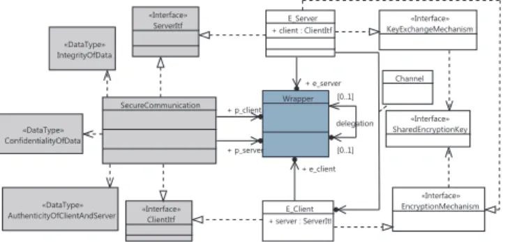
Fig. 17 depicts the expected results of our transformation engine towards component architecture.
Fig. 5.3 describes the mapping between the concepts. As previously, we separate the pattern specification, the internal structure (here the static structure), and the delegation.
6. STATE OF THE ART
In system development, a pattern deals with a specific, recurring problem in the design or implementation. It captures expertise in the form of reusable architecture design themes and styles, which can be reused even when algorithms, component implementations, or frameworks cannot. The design patterns are usually represented using text-based languages, diagrams with notations such as UML object modeling and most often improved by textual
Fig. 16. Secure Communication Pattern: SEPM to Object UML ("−→ means transformed to)
Pattern specification
—DIPattern:SecureCommunication "−→ Class:SecureCommunication —Interface(external, provided):ServerExtItf "−→ Interface:ServerItf —Interface(external, provided):ClientExtItf "−→ Interface:ClientItf —SDProperty:Authenticity "−→ DataType:AuthenticityOfClientAndServer —SDProperty:Confidentiality "−→ DataType:ConfidentialityOfData —SDProperty:Integrity "−→ DataType:IntegrityOfData
Static structure specification
—Entity:Client "−→ Class:Client
—RequiredServerExtItf:port1 "−→ Attribute:server(type:ServerItf) —ProvidedClientExtItf:port2 "−→ realize ClientExtItf
—Entity:Server "−→ Class:Server
—ProvidedServerExtItf:port1 "−→ realize ServerExtItf
—RequiredClientExtItf:port2 "−→ Attribute:client(type:ClientItf) —Entity:KeyExchangeMechanism "−→ Interface:KeyExchangeMechanism —Entity:EncryptionMechanism "−→ Interface:EncryptionMechanism —Entity:EncryptionMechanism "−→ Interface:EncryptionMechanism —Entity:SharedEncryptionKey "−→ Interface:SharedEncryptionKey Interaction specification —ProvidedClientExtItf:port1 "−→ [Client]ProvidedClientExtItf:port2 —Association/ Class:SecureCommunication "−→ Class:Wrapper —ProvidedServerExtItf:port2 "−→ [Client]ProvidedServerExtItf:port1
—Association/ Class:SecureCommunication "−→ Class:Wrapper
Fig. 17. Secure Communication Pattern: Component View
descriptions and examples of code fragments to complete the description [Gamma et al. 1995; Buschmann et al. 1996]. Unfortunately, the use and/or application of pattern can be difficult or inaccurate. In fact, the existing descriptions are not formal definitions and sometimes generate some ambiguities about the exact meaning of the pattern. To give a flavor of the improvement achievable by using specific languages, we look at the pattern modeling (description) problem.
Fig. 18. Secure Communication Pattern: SEPM to Component UML ("−→ means transformed to)
Pattern specification
—DIPattern:SecureCommunication "−→ Component:SecureCommunication —Interface(external, provided):ServerExtItf "−→ Port/Interface:ServerExtItf —Interface(external, provided):ClientExtItf "−→ Port/Interface:ClientExtItf —SDProperty:Authenticity "−→ DataType:AuthenticityOfClientAndServer —SDProperty:Confidentiality "−→ DataType:ConfidentialityOfData —SDProperty:Integrity "−→ DataType:IntegrityOfData
Static structure specification
—Entity:Client "−→ Component:Client
—RequiredServerExtItf:port1 "−→ P ort / required Interface —ProvidedClientExtItf:port2 "−→ P ort / provided Interface —Entity:Server "−→ Component:Server
—ProvidedServerExtItf:port1 "−→ P ort / provided Interface —RequiredClientExtItf:port2 "−→ P ort / required Interface
—Entity:KeyExchangeMechanism "−→ Component:KeyExchangeMechanism —Entity:EncryptionMechanism "−→ Component:EncryptionMechanism —Entity:EncryptionMechanism "−→ Component:EncryptionMechanism —Entity:SharedEncryptionKey "−→ Component:SharedEncryptionKey Interaction specification —ProvidedClientExtItf:port1 "−→ [Client]ProvidedClientExtItf:port2 —Delegation Connector —ProvidedServerExtItf:port2 "−→ [Client]ProvidedServerExtItf:port1 —Delegation Connector
Pattern Modeling Language Approaches.A number of modeling languages have been proposed in the literature. In particularly, modeling pattern in the UML context. In [Fontoura and Lucena 2001; Sanada and Adams 2002] authors proposed an approach to improve the representation of design patterns through UML diagrams extensions used to model them. This extension consists of the use of new stereotypes and tagged values to improve the presentation of design pattern configurations.
Another approach uses metamodeling to define pattern concepts in the context of the UML metamodel. For example, in [A. L. Guennec and Jézéquel 2000], authors propose a minimal set of modifications to the UML 1.3 metamodel to make it possible to model design patterns and represent their occurrences in UML, opening the way for some automatic processing of pattern applications within CASE tools. Work in [?] aims at providing a modeling language that can truly reveal the abstract nature of design patterns. Authors suggested an extension to UML 1.5 and they make use of the metamodeling techniques as by using collaboration diagram to specify the collaboration among model elements. All these works discuss patterns in the context of UML and limit their application to UML.
The approach in [Mikkonen 1998] promotes a precise representation of design patterns by formalize temporal behaviors of patterns using a specification method named DisCo. Other works propose to formalize patterns like LePUS in [Eden et al. 1998] as a declarative, higher order language, designed to represent the generic solution indicated by design patterns. The DPML (Design Pattern Modeling Language) [Mapelsden et al. 2002] is a visual language for modeling design pattern solutions and their instantiations in object oriented designs of software systems.
Pattern Languages. Patterns are often defined as isolated entities. In this case, patterns provide a design solution very specific to a unique problem. A pattern language represents a collection of solutions for recurring problems as proposed by Alexander [Alexander et al. 1977]. Software engineering applied design patterns for expressing object/component-oriented software design experience. Hence, Patterns are proposed for both Object and Component-Oriented Software Development. Design patterns for component-oriented programming are distin-guished from object-oriented patterns in two ways. First, the elements of the patterns are components - or they
describe the inner structure of a single component. Secondly, delegation and forwarding, is used exclusively as interaction mechanism for (weak) coupling of components [Rege 1999]. In [Noble 1998] and in the context of a project called Found Objects, Noble presents a pattern language to organize patterns for object-oriented design by analyzing the patterns and the relationships between them. Organizing patterns into languages has the potential to make large collections of patterns easier to understand and to use. The proposed language has three architectural pattern fragments. The most important fragment is the OO Program fragment. The other architectural fragments describe architectural composite patterns and the Interpreter fragment contains only the Interpreter pattern, the sole larger-scale pattern from Design Patterns.
7. CONCLUSION
This paper deals with pattern and MDE (i.e. Model Driven Engineering) approach to structure and transform a pattern from a common representation to a specific software construct. Reaching this target requires getting to (i) a common representation of patterns for several domains and (ii) a flexible structure for a pattern. The solution envisaged here is based on meta-modeling techniques to represent patterns at a greater level of abstraction. Therefore, patterns can be stored in a repository and can be loaded in function of desired properties. As a result, patterns will be used as brick to build a applications through a model driven engineering approach.
In previous works we have defined a metamodel of S&D pattern which provides a set of concepts for describing them. In this paper we propose to use patterns in the context of the well-known UML standard to design object-oriented and component-object-oriented software architecture. Firstly, we specify our pattern modeling language (SEPM) using the Meta Object Facility (MOF) constructs, a OMG standard for describing modeling languages. Secondly, we propose a mapping between SEPM and UML (object and component). This mapping is concretely expressed by a set of transformation rules using the Ecore metamodels to specify input metamodels and Operational QVT specification to encode the proposed transformation engine. We have successfully illustrated the approach with a case study: the secure communication pattern.
The next step of this work consists in implementing other patterns including those for security and dependability to build a repository of S&D patterns. Another objective for the near future is to provide guidelines concerning both the integration of pattern in an application based on object and/or component paradigms. With regard to the tool suite, we plan the development of a graphical and/or textual DSL editor on the one hand and the use of the QVT transformation rules as part of its functionalities.
Acknowledgments.This work is initiated in the context of SEMCO framework. It is supported by the European FP7 TERESA project and by the French FUI 7 SIRSEC project. In addition, we would like to thank our shepherd David West who gave us valuable feedback on this paper.
REFERENCES
A. L. Guennec, G. S. and Jézéquel, J.-M. 2000. Precise modeling of design patterns. In In Proceedings of UML’00. In Proceedings
of the third International Conference on the Unified Modeling Language (UML 2000).
Alexander, C., Ishikawa, S., and Silverstein, M. 1977. A Pattern Language. Center for Environmental Structure Series Series, vol. 2. Oxford University Press, New York, NY.
Buschmann, G., Meunier, R., Rohnert, H., Sommerlad, P., and Stal, M. 1996. Pattern-Oriented Software Architecture: a
system of patterns. Vol. 1. John Wiley and Sons.
Eden, A. H., Hirshfeld, Y., and Yehudai, A. 1998. LePUS - A Declarative Pattern Specification Language, Technical Report 326/98, Department of Computer Science, Tel Aviv Uni.
Fontoura, M. and Lucena, C. 2001. Extending UML to improve the representation of design patterns. Journal of Object-Oriented
Programming 13, 12–19.
France, R.-B. and Rumpe, B. 2005. Domain specific modeling. Software and System Modeling 4, 1, 1–3.
Gamma, E., Helm, R., Johnson, R. E., and J.Vlissides. 1995. Design Patterns: Elements of Reusable Object-Oriented Software. Addison-Wesley.
Gray, J., Tolvanen, J.-P., Kelly, S., Gokhale, A., Neema, S., and Sprinkle, J. 2007. Domain-Specific Modeling. Chapman & Hall/CRC.
Hamid, B., Gürgens, S., Jouvray, C., and Desnos, N. 2011. Enforcing S&D Pattern Design in RCES with Modeling and Formal Approaches. In MoDELS. 319–333.
Harel, D. and Rumpe, B. 2000. Modeling Languages: Syntax, Semantics and All That Stuff Part I: The Basic Stuff. Tech. rep. Kleppe, A. G. 2007. A Language Description is More than a Metamodel. In Fourth International Workshop on Software Language
Engineering, Nashville, USA. megaplanet.org, Grenoble, France.
Kleppe, A.-G., Warmer, J., and Bast, W. 2003. MDA Explained: The Model Driven Architecture: Practice and Promise. Addison-Wesley Longman Publishing Co., Inc., Boston, MA, USA.
Mapelsden, D., Hosking, J., and Grundy, J. 2002. Design Pattern Modelling and Instantiation using DPML.
Mikkonen, T. 1998. Formalizing design patterns. In Proceedings of the 20th international conference on Software engineering. ICSE ’98. IEEE Computer Society, Washington, DC, USA, 115–124.
Miller, J. and Mukerji, J. 2003. MDA Guide Version 1.0.1. Tech. rep., Object Management Group (OMG). Noble, J. 1998. Towards a Pattern Language for Object Oriented Design. Published by the IEEE Computer Society, 2. OMG. 2006. Meta Object Facility (MOF) Core Specification - OMG Available Specification Version 2.0.
OMG. 2008. Meta Object Facility ( MOF ) 2 . 0 Query / View / Transformation Specification. Transformation April, 1–230. OMG. 2009. OMG Unified Modeling Language (OMG UML), Superstructure. http://www.omg.org/spec/UML/2.2/Superstructure. OMG. 2010. OCL 2.2 Specification.
Rege, K. 1999. Design Patterns for Component-Oriented Software Development. In EUROMICRO. 2220–2228.
Sanada, Y. and Adams, R. 2002. Representing Design Patterns and Frameworks in UML-Towards a Comprehensive Approach.
Journal of Object Technology 1, 143–154.
Schmidt, D. 2006. Model-driven engineering. in IEEE computer 39, 2, 41–47.
Steinberg, D., Budinsky, F., Paternostro, M., and Merks, E. 2009. EMF: Eclipse Modeling Framework 2.0 2nd Ed. Addison-Wesley Professional.