HAL Id: in2p3-00435463
http://hal.in2p3.fr/in2p3-00435463
Submitted on 24 Nov 2009
HAL is a multi-disciplinary open access
archive for the deposit and dissemination of
sci-entific research documents, whether they are
pub-lished or not. The documents may come from
teaching and research institutions in France or
abroad, or from public or private research centers.
L’archive ouverte pluridisciplinaire HAL, est
destinée au dépôt et à la diffusion de documents
scientifiques de niveau recherche, publiés ou non,
émanant des établissements d’enseignement et de
recherche français ou étrangers, des laboratoires
publics ou privés.
Design of the high intensity exotic beams SPIRAL 2
project
M.H. Moscatello, A. Mosnier
To cite this version:
M.H. Moscatello, A. Mosnier. Design of the high intensity exotic beams SPIRAL 2 project. 2005
Particle Accelerator Conference (PAC05), May 2005, Knoxville, United States. pp.2044-2046.
�in2p3-00435463�
DESIGN OF THE HIGH INTENSITY EXOTIC BEAMS SPIRAL 2 PROJECT
M.H. Moscatello, GANIL, Caen, France
A. Mosnier
#, CEA-DAPNIA, Gif-sur-Yvette, France
Abstract
The SPIRAL 2 facility will be able to deliver stable heavy ion beams and deuteron beams at very high intensity, allowing to produce and accelerate light and heavy rare ion beams. The driver will accelerate a 5 mA deuteron beam up to 20 MeV/u and also q/A=1/3 heavy ions up to 14.5 MeV/u. The injector consist of the ion sources, a 4-vane RFQ and the low and medium beam transfer lines. It is followed by an independently phased superconducting linac with compact cryostats separated with warm focusing sections. The overall design, results of beam dynamics simulations with combined errors, as well as results of tests of prototypes for the most critical components of the accelerator are presented.
INTRODUCTION
The SPIRAL 2 project [1] aims at delivering high intensities of rare isotope beams by adopting the best production method for each respective radioactive beam. The unstable beams will be produced by the ISOL “Isotope Separation On-Line” method via a converter, or by direct irradiation and by in-flight techniques. The combination of all these techniques (i.e. via fission induced by fast neutrons in a uranium target or by direct bombardment of the fissile material, or via fusion-evaporation with unstable beams or heavy ion beams) will allow to cover broad areas of the nuclear chart. In addition to fundamental research in nuclear physics, the SPIRAL 2 facility could also offer a high performance multidisciplinary tool, especially in fields of science requiring high fluxes of neutron, such as material
sciences, atomic, plasma and surface physics.
The driver must accelerate beams of high power (200 kW deuteron beam power), different ion species and mass-to-charge ratios (deuterons as well as heavier ions with mass-to-charge ratio A/q=3 and up to A/q=6 at a later stage) with high output-energy flexibility (from 40 MeV deuteron energy down to energies, as low as that at the RFQ exit). The concept of “Independently Phased Superconducting Linac” has been chosen because it provides safe continuous wave (CW) operation and high flexibility in the acceleration of different ion species and charge-to-mass ratios. A schematic view of the accelerator is shown in Figure 1.
Injector
One injector will deliver both kinds of ion beams at the required energy of 0.75 MeV/u. Two types of deuteron source have been developed: the SILHI-type source by DAPNIA/Saclay and the Micro-Phoenix source by LPSC/Grenoble. Both met the emittance and current
specifications (~ 0.1 π mm mrad at 5 mA).
For the A/q=3 ions, the present state-of-the-art of ECR
sources produces 1 mA for O6+ and 0.3 mA for Ar12+. The
reference project will start with such a source at
intermediate intensity. High confinement fields (B~2-3 T)
and high frequency (f > 28 GHz) are required to increase the ion beam currents. The A-Phoenix source (60 kV, 28 GHz), based on the combination of permanent and high temperature superconducting magnets, will permit to reach the highest intensities for noble gases. This source is under development at LPSC and should reach the
___________________________________________
# [email protected] Figure 1: Schematic view of the accelerator.
Proceedings of 2005 Particle Accelerator Conference, Knoxville, Tennessee
expected performance before 2008. For the production of metallic ions (Ni, Cr, etc), the required R&D will go on after the start of the facility and can be carried out at GANIL or at LPSC.
The RFQ cavity must bunch and accelerate the beam to the required energy with a high transmission to allow for hands-on maintenance. Different technologies at 88 MHz were studied and the four-vane structure was finally chosen because of the lowest RF power consumption and of the experience on this type of structure of the team involved. The power tests on a 1 m long prototype were successful and are reported below.
Superconducting Linac
The choice of short superconducting cavities, exhibiting very wide velocity acceptance in comparison with long multi-cell structures, allows the optimisation of the output energy for each ion specie by re-adjusting the individual RF phases. Two types of superconducting cavities were considered - Quarter-Wave Resonators (QWR) and Half-Wave Resonators (HWR) - and several different frequency scenarios have been studied. The use
of 2 families of QWR resonators at 88 MHz (β=0.07 and
β=0.12) was finally adopted for the following reasons: • lower total number of cavities
• no frequency jump which would require longitudinal matching
• larger cavity aperture
• identical frequency for all RF power sources • moderate cost
In addition, the focusing by means of room-temperature quadrupoles, instead of superconducting solenoids, resulting in one cryostat per focusing lattice, has been chosen. Despite a slight cost increase, this arrangement offers many advantages: residual magnetic field of solenoids close to superconducting resonators too high, much simpler cryostats, much easier cavity and magnet alignment, larger space available for diagnostics and simpler linac tuning.
A realistic accelerating field of 6-7 MV/m was chosen because the resulting maximum peak fields (Epk < 40 MV/m, Bpk < 80 mT) can be achieved without too much effort by using well-tried methods developed in the last ten years, such as high-pressure rinsing, high-purity niobium and clean conditions. Furthermore, free room has been left at the end of the linac to allow for the
insertion of two additional high-β cryomodules should the
field gradient in operation be lower than expected.
BEAM DYNAMICS SIMULATION
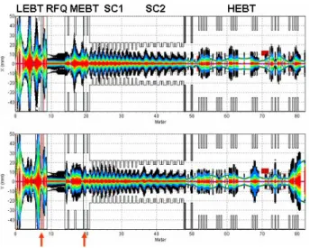
Intensive beam dynamics studies and simulations have been carried out to ensure a robust design and a very low beam loss along the linac. Multiparticle simulations are performed from the Low Energy Beam Transport (LEBT) line to the target through the radio frequency quadrupole (RFQ), the Medium Energy Beam Transport (MEBT), the two superconducting sections (SC1, SC2) and the High Energy Beam Transport (HEBT) line. Several elements
are simulated using 3D field maps: LEBT quadrupoles, RFQ and QWRs. Figure 2 shows the beam radial density without errors. Collimators (red arrows) are located in the LEBT and at the end of the MEBT to get rid of the beam halo coming from the source.
Figure 2: Beam radial density along the accelarator. All kinds of static and dynamic errors were considered and the tolerances can be roughly summarised as follows:
• displacement of warm components around ± 0.1 mm (RFQ, quadrupoles, octupoles)
• displacement of cold components ± 1 mm (QWRs) stability of the RF amplitude and phase: 1% and ± 1° Diagnostics are used for trajectory correction (22 beam position monitors BPM) and beam tuning (17 profilers and 1 emittance measurement). The beam steerers are correction coils inserted in the quadrupoles. In the superconducting linac, profile monitors are needed in the first 6 periods to retune the beam in case of mismatching. Downstream, only BPMs are used. As the steering effect due to the QWRs is small with deuteron beams, it is only corrected by the steerers.
In order to obtain a good guess on beam loss
estimation, 106 particles were tracked in an ensemble of
341different linacs [2]. Figure 3 shows the profile of the beam loss, averaged on the 341 machines.
Figure 3: Average beam loss (W) along the linac. Except for the collimators, the hands-on maintenance
requirement, lower than 1 W/m, is well satisfied
Proceedings of 2005 Particle Accelerator Conference, Knoxville, Tennessee
everywhere in the linac. The “hottest” components are
one quadrupole in the low-β section and the first QWR in
the high-β section. From the beam loss distribution
density g(p), calculated at a specific location for an ensemble of different linacs, we can define the probabilty (Confidence Level CL) that, given the specified tolerances, any specific linac will have a beam loss lower than the design limit Pmax:
∫
max = 0 ( ) P CL dp p gThe simulations showed that, for the design limits of 5 W for quadrupole and 1 W for QWR, the Confidence
Level is still higher than 98% for these two “hottest”
components.
PROTOTYPE TEST RESULTS
RFQ
In order to lower the cost and to avoid the brazing risks, the 88 MHz 4-vane RFQ is a pure mechanical assemby made from a cheap copper tube without any brazing. The vanes are produced from standard thickness laminated copper. In addition, as the vanes are dismountable, it allows a possible future evolution of the RFQ. A view of the 1 m long prototype module is shown in Figure 4.
Figure 4: RFQ cavity prototype.
The power tests [3] were performed at the INFN - Laboratory National del Sud (LNS) in Catania. The achieved power, infered from both direct RF power measurement and X-rays, was 50 kW for a design power of 40 kW corresponding to a 110 kV vane voltage. After cavity dismantling, the RF gaskets were carefully inspected and did not show any damage. The next step will be the precise measurement of the vane displacement during the powering-up.
QWR
The geometry of both QWRs was optimized for both mechanical and electromagnetic properties (Table 1).
The definition of the accelerating field used is:
∫
= E e dz Eacc z jωzβc λ β 1 Table 1: RF parameters of QWRs β = 0.07 β = 0.12 Epeak/Eacc 5.0 5.5 Bpeak/Eacc mT/(MV/m) 8.75 10.1 Rs/Q Ohms 632 521 Q0 x 109 2.2 1.7In order to appraise different options [4], the low-β prototype has a movable bottom plate, making easier the high-pressure rinsing, whereas the high-β prototype is a fully welded structure, avoiding any risk of additional RF loss. Figure 5 show the results of the tests at 4.2 K. Both QWRs exceed by far the design gradient of 6.5 MV/m. The gradient limitation of the low-β prototype, just below 10 MV/m, comes from a not enough cooled bottom plate
during the experiment and the high-β prototype exhibited
some multipacting barriers below 2 MV/m. It is worth
noting the high Q0 achieved by the high-β prototype at
low field.
Figure 5: First Q0 measurements for low-β (top) and
high-β (bottom) prototypes.
REFERENCES
[1] The SPIRAL 2 Project APD Report, January 2005. [2] R. Duperrier and D. Uriot, “Start to End Error Study
for the SPIRAL2 Linac”, these proceedings.
[3] R. Ferdinand et al, “SPIRAL 2 RFQ Prototype Tests”, these proceedings.
[4] S. Chel et al, “Low-Beta SC Quarter-Wave Resonator and Cryomodule for SPIRAL2”, these proceedings.
Proceedings of 2005 Particle Accelerator Conference, Knoxville, Tennessee