HAL Id: hal-02444281
https://hal.archives-ouvertes.fr/hal-02444281
Submitted on 17 Jan 2020
HAL is a multi-disciplinary open access
archive for the deposit and dissemination of
sci-entific research documents, whether they are
pub-lished or not. The documents may come from
teaching and research institutions in France or
abroad, or from public or private research centers.
L’archive ouverte pluridisciplinaire HAL, est
destinée au dépôt et à la diffusion de documents
scientifiques de niveau recherche, publiés ou non,
émanant des établissements d’enseignement et de
recherche français ou étrangers, des laboratoires
publics ou privés.
Functional patterned multiphoton excitation deep inside
scattering tissue
Eirini Papagiakoumou, Aurélien Bègue, Ben Leshem, Osip Schwartz, Brandon
Stell, Jonathan Bradley, Dan Oron, Valentina Emiliani
To cite this version:
Eirini Papagiakoumou, Aurélien Bègue, Ben Leshem, Osip Schwartz, Brandon Stell, et al.. Functional
patterned multiphoton excitation deep inside scattering tissue. Nature Photonics, Nature Publishing
Group, 2013, 7 (4), pp.274-278. �10.1038/NPHOTON.2013.9�. �hal-02444281�
×
Functional patterned multiphoton excitation deep
inside scattering tissue
Eirini Papagiakoumou
1, Aure
´lien Be`gue
1, Ben Leshem
2, Osip Schwartz
2, Brandon M. Stell
3,
Jonathan Bradley
3, Dan Oron
2*
and Valentina Emiliani
1*
Stochastic distortion of light beams in scattering samples makes in-depth photoexcitation in brain tissue a major challenge. A common solution for overcoming scattering involves adaptive pre-compensation of the unknown distortion1–3. However, this requires long iterative searches for sample-specific optimized corrections, which is a problem when applied to optical neurosti- mulation where typical timescales in the system are in the milli- second range. Thus, photoexcitation in scattering media that is independent of the properties of a specific sample would be an ideal solution. Here, we show that temporally focused two- photon excitation4 with generalized phase contrast5 enables photoexcitation of arbitrary spatial patterns within turbid tissues with remarkable robustness to scattering. We demon- strate three-dimensional confinement of tailored photoexci-tation patterns >200 mm in depth, both in numerical simulations and through brain slices combined with patch- clamp recording of photoactivated channelrhodopsin-2.
Recent advances in biochemistry and genetic engineering have allowed the control of cellular activation and inhibition using light, either via the photorelease of caged compounds or using optogenetic light-gated channels and pumps6,7. These tools have enabled the analysis of genetically defined neuronal populations within intact neuronal circuits, primarily using one-photon wide- field illumination8–11
. However, one-photon methods are limited by both a lack of optical sectioning and the low penetration depth induced by scattering. For example, photoactivation of a small subset of genetically identical interconnected cells beneath the surface of brain tissue is incompatible with one-photon excitation. Two-photon excitation provides superior axial resolution while mitigating the effects of scattering due to the dominance of ballistic photons inherent in the nonlinear two-photon excitation process and the longer excitation wavelength12. In contrast to one-photon excitation, a major limitation in using two-photon excitation for photoactivation can be that a critical number of activable targets necessary to obtain the desired outcome is physically unachievable within the volume of a two-photon diffraction-limited spot; for example, not enough channelrhodopsin molecules are activated to generate sufficient depolarization for firing of an action potential13,14. Thus, effective photoactivation of photosensitive compounds calls for a new method with three essential attributes: (i) it should enable the generation of extended shaped patterns, (ii) axial confine- ment should be maintained, and (iii) the excitation pattern should be preserved upon propagation through scattering media.
Extended excitation areas can be generated by fast scanning of a diffraction-limited spot13 or by using low-numerical-aperture (low-NA) two-photon beams13,14. In the first case, axial resolution
is maintained because of the use of a diffraction-limited spot. Still, a rapid loss of temporal resolution limits its use to small areas (that is, single cells)14. Improved temporal resolution (few milliseconds)
has been achieved recently by in-depth (200 mm) photoactivation of
ad hoc engineered opsins15. However, to achieve millisecond temporal resolution these experiments required the use of a high excitation density, which was consequently accompanied by degradation in the axial resolution (tens of micro- metres)15, an inevitable compromise for scanning set-ups.
For low-NA beams, an increased excitation area permits improved temporal resolution, but at the cost of axial confinement. Moreover, in scattering tissue, extended excitation patterns quickly transform into a speckle pattern upon propagation.
Adaptive optics provides a way to improve propagation through scattering samples. Indeed, it was shown recently that photoexcita- tion with a diffraction-limited spot16–20 (or even a set of spots) deep inside scattering media is possible using adaptive wavefront correc- tion2. Adaptive optics is, however, slow, and little data have been
reported on its efficacy in optimizing extended shaped patterns21
. Several years ago, temporal focusing of ultrashort pulses was suggested as a means to generate axially resolved wide-field multi- photon excitation patterns4. In temporal focusing, the desired exci- tation pattern is imaged from the surface of a diffraction grating onto the sample using a dispersion-free telescope. Geometric dis- persion arising from this arrangement axially confines multiphoton excitation within the sample, regardless of the detailed excitation shape22,23. Temporal focusing has recently found various appli-
cations in microscopy24 and lithography25, and has been proven to be an efficient method for the activation of optogenetic channels in single26 and multiple cells23. However, in all these applications, the samples were either transparent or weakly scattering.
Here, we explore the effects of scattering on the propagation of patterned temporal focusing beams through thick brain slices. We find that temporal focusing is remarkably resilient to scattering, maintaining the desired spatial excitation profiles irrespective of the details of the sample scattering. By combining temporal focusing with generalized phase contrast (GPC)5,23, we show that we can maintain accurate control of predetermined excitation volumes more than 200 mm deep inside scattering specimens, and demon- strate photoactivation of channelrhodopsin-2 (ChR2-H134R) with single-cell precision and millisecond temporal resolution in patch- clamp recordings.
We began by considering the effects arising from propagation of a temporally focused beam through a scattering sample. In temporal focusing, the various colours comprising the excitation pulse are dispersed and illuminate the excitation focal plane from different
1 Neurophysiology and New Microscopies Laboratory, Wavefront Engineering Microscopy Group, CNRS UMR 8154, INSERM U603, Paris Descartes University, 45 rue des Saints Pe`res, 75270 Paris Cedex 06, France, 2
Department of Physics of Complex Systems, Weizmann Institute of Science, Rehovot 76100, Israel, 3 Laboratory of Brain Physiology, CNRS UMR 8118, Paris Descartes University, 45 rue des Saints Pe`res, 75270 Paris Cedex 06, France. *e-mail: [email protected]; [email protected]
×
¼
directions (Fig. 1a). In the presence of scattering, each ‘monochro- matic’ component of the pulse samples a different region of the scat- tering medium. This gives rise to two main effects. First, colours with propagation paths that are far apart from one another acquire nearly uncorrelated speckle patterns. Summing these speckle patterns results in an overall smoothing of the image, as shown in Fig. 1b. Second, adjacent colours, propagating along only slightly different angles, result in highly correlated but spatially shifted speckle patterns. This leads to anisotropic smoothing in the direction of the shift, as shown in Fig. 1c. This remarkable ‘self- healing’ quality of temporal focusing beams reveals itself clearly in the following simulations and experiments.
In our numerical modelling we propagated temporally focused and non-temporally focused excitation beams through a scattering phantom: a homogeneous medium of randomly distributed 2 mm dielectric spheres with a refractive index of 0.1 above that of the sur- rounding medium and an average concentration of 1 per 1,000 mm3. This gives rise to a scattering length of 135 mm, similar to that typically observed in brain tissue27. A low-NA excitation beam (Fig. 2a, upper left panel, 100 fs pulses, l 800 nm) propagating through a scattering sample transforms into a speckle pattern within 1–2 scattering lengths, as observed in the simulation pre- sented in Fig. 2a (upper middle panel). In contrast, a temporally focused low-NA beam yields a significantly smoother excitation
a b c
Figure 1 | Description of temporal focusing at the sample plane. a,b, Schematic of colour propagation at the focal plane of a temporally focused beam without scattering (a) and within a scattering medium (b). c, Representation of propagation of adjacent colours within a
scattering medium.
pattern, as seen in the upper right panel of Fig. 2a. Significant ani- sotropic smoothing is also visible (see Supplementary Information on correlation between speckle patterns of ‘neighbouring’ colours for more details).
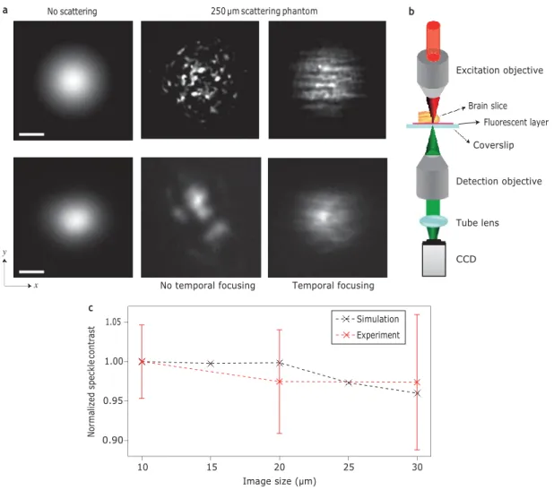
To test this result experimentally, we excited fluorescence at 800 nm on a thin fluorescent layer placed beneath fixed brain slices of various thicknesses (as schematically shown in Fig. 2b and detailed in the Supplementary Methods). We imaged the fluorescent layer using a Gaussian excitation beam (11 mm
a No scattering 250 μm scattering phantom b
Excitation objective Brain slice Fluorescent layer Coverslip Detection objective Tube lens CCD c 1.05
No temporal focusing Temporal focusing
1.00
0.95
0.90
10 15 20 25 30
Image size (μm)
Figure 2 | Propagation of low-NA Gaussian beams. a, Top: two-photon excitation patterns generated by numerical simulation of a low-NA Gaussian beam without scattering (left) and after propagation through a 250 mm scattering phantom without (middle) and with (right) temporal focusing. Bottom: two- photon fluorescence images of a low-NA Gaussian beam without scattering (left) and after propagation through 250 mm of fixed cortical brain slices without (middle) and with (right) temporal focusing. Scale bars, 10 mm. b, Schematic of the experimental configuration used for characterization of beam propagation through different thicknesses of brain tissue. c, Normalized speckle contrast of a temporally focused image as a function of image size. Error bars represent
y x Simulation Experiment No rm al iz ed spe ck le co nt ra st
Temporal focusing No temporal focusing Temporal focusing Temporal focusing Ax ia l r es ol uti on ( μm)
full-width at half-maximum, FWHM) without scattering (Fig. 2a, lower left panel) and after propagation through a brain slice with a thickness of 250 mm, without (lower middle panel) and with (lower right panel) temporal focusing. The experimental observations are in good agreement with the simulation predictions. Without temporal focusing, the excitation pattern transforms into large speckles, the position and size of which vary with location on the slice, whereas the temporal focusing shape is much better preserved. The predicted anisotropic smoothing for temporal focusing beams is also visible.
Before considering the propagation of more complex temporal focusing excitation shapes, we asked whether this smoothing effect depends on the excitation beam size. To test this, we replaced the brain slice with a phantom (a scattering solution of 2.1 mm latex beads) that yields a similar scattering length. The sample was excited for 50 ms intervals, once every 1.2 s, and fluorescence emission was imaged in a synchronized fashion. Over the 1.2 s the beads were ran- domly redistributed due to diffusion. A total of 100 frames were cap- tured for each beam size, creating an ‘ensemble’ of statistically independent speckle patterns, and a measure of the degree of smooth- ing was extracted from the obtained images (see Supplementary Information on speckle contrast over an ensemble average). These results, plotted in Fig. 2c with the simulation results, clearly show that smoothing is nearly independent of beam size.
We then turned to testing the dependence of the degree of smoothing on excitation shape. For this, a beam-shaping apparatus based on the GPC method5 was inserted in the illumination beam path before the temporal focusing grating (Supplementary Methods), enabling the creation of arbitrary excitation patterns. We started
by using a uniform round spot with a diameter of 15 mm as the exci- tation pattern. Comparing Figs 2a (lower right panel) and 3a, the temporal focusing–GPC excitation pattern is seen to retain its form even better than the Gaussian one, while the circular shape is almost non-discernible without temporal focusing, demonstrating the difficulty in using such an approach for in-depth photoactiva- tion. We used two measures to quantitatively characterize the distor- tion of the desired shape (see Supplementary Information on quantification of transmitted image quality). The first, pattern dis- tortion, involves the cross-correlation of the obtained GPC pattern with the undistorted desired one. The second characterizes the illu- mination non-uniformity within the excitation shape. For the circu- lar excitation pattern, pattern distortion improves from 0.80 to 0.98, compared with an improvement from 0.84 to 0.97 for the corre- sponding Gaussian patterns (Supplementary Table S1). To under- stand this, one must consider the fact that distortions arise primarily from the interference of weaker scattered waves with the stronger unscattered ones, which serve as a ‘local oscillator’ and amplify their effect. For the spatially smooth illumination pattern, as in the case of the Gaussian beam, this occurs throughout the entire pattern. For a shape with sharp edges, as in GPC, light scat- tered outside it is too weak to induce two-photon excitation.
The ability of temporal focusing–GPC excitation to retain images with fine details (micrometre precision) is illustrated in Fig. 3b, where the excitation pattern is based on the fluorescence image of a Purkinje cell. The only observed distortion is a slight smearing of the fine features, in qualitative agreement with analytical predic- tions28. For all the presented cases, the improvement in the
a No scattering
1
250 μm cortical brain slices 0.10
c
0.22 16
12
0 0.00
b 250 μm cortical brain slices
1 0.15
0 0.00
d 550 μm cortical brain slices
1 0.19 8 0.00 4 0.37 0 e 20 0.00 16 0.09 12 0 100 200 Slice thickness (μm) 300 8 4 0 0.00 0.00 0 0 300 400 500 600 Slice thickness (μm)
Figure 3 | Shape propagation through brain slices. a, Two-photon fluorescence x–y cross-sections of a 15 mm GPC-generated spot after propagation through 250 mm of fixed cortical brain slices (l ¼ 800 nm). b, Fluorescence images of GPC-generated excitation patterns mimicking a Purkinje cell, as in a. c, FWHM of the axial intensity distribution of the GPC spot versus scattering depth. Simulations at 800 nm (black) and 950 nm (blue) are compared with 800 nm experiments (orange). d, Two-photon fluorescence images of the GPC pattern mimicking a neuron with small processes, after propagation through acute cortical brain slices of 550 mm (l ¼ 950 nm). e, FWHM of the axial intensity distribution versus scattering depth, measured on the soma (red) and the apical dendrite (blue), for the excitation shape shown in d. In a, b and d, left panels are obtained from unscattered beams, middle panels with scattered but not temporally focused beams and right panels using scattered temporally focused beams (right). Scale bars, 10 mm. Error bars in c and e represent the standard deviation of measured values at multiple locations.
Theory (800 nm) Theory (950 nm) Experiment (800 nm) No temporal focusing No temporal focusing Ax ia l r es ol uti on ( μm) Soma Dendrite
¼ ¼ ¼ ¼ × ¼ ¼ × × a b c 300
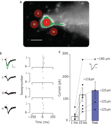
Finally, we tested photostimulation of ChR2–H134R at depth, in slices of cerebellar cortex. Molecular layer interneurons expressing ChR2 were recorded under whole-cell patch-clamp conditions close to the surface of a 250-mm-thick slice, while patterned two- photon illumination was projected through the slice from below. Figure 4 demonstrates that under these conditions ChR2 could be activated to generate large inward currents when recorded in voltage-clamp mode (118+31 pA, spot diameter of 15 mm, for 10 ms, depth of 201+9 mm, n 7 cells; Fig. 4c). To test the spatial restriction of the patterned illumination, we used a 7-mm- diameter spot and positioned it on the centre of the cell soma (Fig. 4a(i)), as well as at various locations around this position
i ii iii iv 1 6 1 6 1 6 1 6 −250 0 250 200 100 ~218 μm ~180 μm ~225 μm ~225 μm ~225 μm
(Fig. 4a(ii–iv)). The pattern evoked currents of different amplitudes at the different positions (Fig. 4b), suggesting that ChR2 activation was restricted to the pattern. The different current amplitudes when the spot was placed at various positions around the cell (ii–iv) are likely to have resulted from fine cellular processes (that is, the den- drites) crossing the excited region. When the pattern was enlarged to completely cover the cell soma (Fig. 4a, green pattern) the result- ing current also increased (Fig. 4b, green trace, top panel), providing further evidence that ChR2 activation is restricted to the pattern. Finally, when positioned on the cell soma, even the 7-mm-diameter spots evoked currents large enough to reliably evoke action poten- tials in current clamp (Fig. 4b, right panels).
In summary, we have found that temporal focusing is an
extre-Time (ms) 0 1 ms 10 ms Peak mely robust method for projecting shaped images deep into a scat-
tering specimen, and we have elucidated the physical mechanisms Figure 4 | Photostimulation of channelrhodopsin-2 in brain slice. a, Spots
(i–iv): illumination patterns of 7 mm diameter each, overlayed on a CCD image of a molecular layer interneuron filled with 10 mM Alexa 594 (scale bar, 10 mm). Green illumination pattern targets the soma and part of a visible neurite. b, Left: average currents (n ¼ 3) recorded in voltage clamp during 10 ms laser pulses delivered at 30 s intervals at corresponding positions in a. Scale bars, 20 pA and 20 ms. Right: raster plots of action potentials recorded in current clamp from six traces (at 30 s intervals, 10 ms laser pulses, red bars; l ¼ 950 nm). Excitation depth, ×240 mm. c, Average currents (black dots) at 1 ms, 10 ms or at the peak (recorded at 19.9+1.8 ms) of a 50 ms exposure (n¼ 6 trials, 30 s intervals). Connected dots correspond to recordings from the same cell (depths denoted). Average currents over the six cells are represented by bars. Error ¼ s.e.m. Inset: average current from the cell recorded at 218 mm. Scale bars, 50 pA and 20 ms.
preservation of the excitation pattern is reflected in a two- to three- fold decrease in non-uniformity and pattern distortion values approaching unity (see Supplementary Information on quantifi- cation of transmitted image quality).
Axial confinement was reasonably well maintained deep within the scattering medium, as shown in Fig. 3c. The axial resolution started to deviate from that measured without scattering (2.8+ 0.1 mm) for propagation depths of about one scattering length (here ℓs 135+12 mm, see Supplementary Information on scattering length of fixed slices). For thinner samples, scattering only led to an increased signal at the tails of the axial response. For greater depths, the axial resolution started to deteriorate, reach- ing a value approximately five times larger at 2ℓs, in agreement with
the results of Dana and Shoham29.
To quantify the maximum depth for performing photostimulation through live tissue, we tested the propagation of GPC patterns through acute juvenile rat cortical brain slices, using an excitation wavelength of 950 nm, which is both optimal for excitation of photo- activable ion channels and mitigates the effects of scattering (Fig. 3c). Figure 3d presents images of the excitation pattern after propagation through acute slices (550 mm). The average FWHM measured on the part of the fluorescent shape mimicking the soma or the principal dendrite is shown in Fig. 3e. In general, no significant differences between propagation in fixed and acute slices were found.
behind this phenomenon. Using temporal focusing, we demonstrate in-depth photoactivation of ChR2 in brain slices. These results indicate that the superior robustness of shaped excitation patterns obtained with temporal focusing make it a promising approach in the use of two-photon optogenetics in in vivo applications.
Methods
Optical set-up for beam propagation characterization. The light source used for the experiments was a mode-locked Ti:sapphire laser (Mai Tai, Spectra-Physics; Dt 100 fs, Dl 10 nm, repetition rate 82 MHz), with the output beam power controlled by a half-wave plate and a polarizer.
The characterization of beam propagation through the different types of brain slices was carried out in a microscope configuration with two oppositely placed objectives (Fig. 2b), as described in previous work21,30. A detailed description of the set-up is provided in the Supplementary Methods.
Optical set-up for photoactivation at depth. The optical set-up for photoactivation was built around a commercial upright microscope (Zeiss, Axio Examiner.Z1) equipped with a set-up for electrophysiological recordings and modified to perform laser stimulation from the bottom of the brain slice, deep within the slice. To this end, the condenser of the microscope was replaced with an objective lens (Olympus, LUMPLFL60xW/IR2, NA 0.90) through which the excitation laser beam
(l 950 nm) was sent to the sample. The objective was mounted on a precision stage (Newport, M-UMR3.5) and on a piezo positioner (PI, PIFOC P-721.CDQ) for fine adjustments of its position. The excitation optical set-up is described in detail in the Supplementary Methods. For photoactivation experiments we replaced the grating with a 300 l mm21 grating, so that the axial resolution of the excitation patterns (measured to be 7.5+0.7 mm FWHM) was suitable for covering a whole cell soma.
Bright-field imaging for patching the cells and wide-field fluorescence imaging of YFP (by using the appropriate set of filters; TxRed-4040C BrightLine single-band filter set, Semrock) for identification of the ChR2 positive cells were carried out through the imaging path of the microscope with a Zeiss W Plan-Apochromat 63, 1.0 objective on a charge-coupled device (CCD) camera.
The common focal plane between the excitation objective and the imaging objective was retrieved each day, before the photoactivation experiment, by imaging fluorescence excited with the temporal focusing–GPC patterns on a rhodamine-6G coverslip. The coverslip was then removed and the brain slice (250 mm thick) was placed in the sample chamber. Cells were patched close to the surface of the brain slice (10–70 mm deep), and the movement of the imaging objective was compensated by corresponding movement of the excitation objective. Because excitation in this configuration was performed through the bottom surface of the slice, excitation depths varied from 180 mm to 240 mm. Fine-tuning for retrieving the position of the temporal focusing plane and thus maximizing the cell response was performed by micrometric movement of the objective using the piezo positioner. When the temporal focusing plane was retrieved, YFP fluorescence
ii iii i iv Sw ee p nu m be r Cu rr en t (p A)
×
The duration of the laser pulses for photoactivation was controlled by an electrooptic modulator (Conoptics, Model 302RM) controlled by a programmable pulse generator (Master 8, A.M.P.I.), which synchronized the electrooptic modulator based on a trigger pulse sent by an electrophysiology amplifier (Axon 200B). The power density used during photoactivation experiments was 0.45 mW mm22 at the bottom surface of the brain slice. No obvious photodamage was observed and neurons were able to spike for as long as the experimental protocol lasted (often more than 30 min).
Preparation of fixed slices. All experiments followed European Union and institutional guidelines of the care and use of laboratory animals (Council directive 86/609 EEC). Postnatal Sprague–Dawley rats (days 19–30) were perfused transcardially with a 4% paraformaldehyde solution in 0.1 M phosphate buffered saline (PBS). Brains were extracted and post-fixed overnight at 4 8C. Coronal cortical slices, from 50 mm to 250 mm, were obtained on a Leica VT1000 slicer and kept in PBS containing sodium azide (0.01%) at 4 8C. Slices were observed in the optical set-up in a PBS solution.
We performed our study always in the cortex area (layer II–III or layer IV) in order to be consistent for all measurements and not to introduce further variations into the results due to the heterogeneity of different brain regions.
Preparation of acute cortical slices. Coronal cortical slices (250–550 mm) were obtained using a Leica VT1200S slicer from postnatal rats (between 21 and 28 days) in an ice-cold slicing solution containing 125 mM NaCl, 1.25 mM KCl,
1 mM CaCl2 , 1.5 mM MgCl2 , 1.25 mM KH2PO4 , 25 mM NaHCO3 and
16 mM glucose. The slices were incubated in a chamber containing the same solution at 33 8C for 30 min, then left at room temperature. The solutions were oxygenated (95% O2 , 5% CO2) throughout the whole experiment. Slices were
observed in the microscope configuration of Fig. 2b in a HEPES-based solution containing 132 mM NaCl, 4 mM KCl, 1 mM MgCl2 , 2.5 mM CaCl2 ,
2 mM NaHCO3 , 10 mM HEPES and 25 mM glucose (pH 7.3). All reagents were
purchased from Sigma Aldrich.
Cerebellar ChR2–H134R expression. Animals (six weeks old) were put under deep anaesthesia with intraperitoneal injection of ketamine (14.8 mg g21)/xylane
(10 mg g21) and mounted in a stereotaxic frame. A midline sagittal incision was
made to expose the cranium over the cerebellar vermis. At the site of injection (6 mm from Bregma and 0.6 mm lateral) a 0.5 mm burr hole was drilled and a 36-gauge stainless-steel bevelled needle (WPI-nanofil) was slowly lowered 0.4 mm through a small slit cut in the meninges. After a 2 min pause, the needle was retracted 50 mm and 1.3 ml (5.0 1010 total genome copies) of
AAV.hSyn.ChR2(H134R)-YFP (University of Pennsylvania vector core) was injected at a rate of 0.1 ml min21. Once completed, the needle was left in place for an additional 10 min before being withdrawn. The scalp was sutured, and the mouse kept under a warming lamp until it had recovered from the anaesthesia, then finally returned to standard housing. Expression was for 21 days.
Cerebellar slices. Animals were anaesthetized with 2,2,2-tribromo-ethanol (avertin; 0.03 ml g21) and cardiac perfused with an ice-cold low-sodium solution (N-methyl- D-glucamine (NMDG)) (93 mM), KCl (2.5 mM), NaH2PO4 (1.25 mM), NaHCO3
(30 mM), HEPES acid (20 mM), glucose (25 mM), thiourea (2 mM), Na-ascorbate (5 mM), Na-pyruvate (3 mM), CaCl2 (0.5 mM), MgSO4 (10 mM), pH 7.3), which
was also used for sagittal slicing of the vermis. Slices were transferred to oxygenated BBS (in mM; glucose 10, CaCl2 2, MgCl2 1, NaHPO4 1.3, NaHCO3 26, KCl 2.4, NaCl
130) at 34 8C for 40–60 min, then kept at room temperature.
References
1. Vellekoop, I. M., Lagendijk, A. & Mosk, A. P. Exploiting disorder for perfect focusing. Nature Photon. 4, 320–322 (2010).
2. Vellekoop, I. M. & Mosk, A. P. Focusing coherent light through opaque strongly scattering media. Opt. Lett. 32, 2309–2311 (2007).
3. McCabe, D. J. et al. Spatio-temporal focusing of an ultrafast pulse through a multiply scattering medium. Nature Commun. 2, 447 (2011).
4. Oron, D., Tal, E. & Silberberg, Y. Scanningless depth-resolved microscopy.
Opt. Express 13, 1468–1476 (2005).
5. Glu¨ckstad, J. Phase contrast image synthesis. Opt. Commun. 130, 225–230 (1996).
6. Gorostiza, P. & Isacoff, E. Y. Optical switches for remote and noninvasive control of cell signaling. Science 322, 395–399 (2008).
7. Deisseroth, K. Optogenetics. Nature Methods 8, 26–29 (2011).
8. Trigo, F. F., Corrie, J. E. & Ogden, D. Laser photolysis of caged compounds at 405 nm: photochemical advantages, localisation, phototoxicity and methods for calibration. J. Neurosci. Methods 180, 9–21 (2009).
9. Wyart, C. et al. Optogenetic dissection of a behavioural module in the vertebrate spinal cord. Nature 461, 407–410 (2009).
10. Busskamp, V. et al. Genetic reactivation of cone photoreceptors restores visual responses in retinitis pigmentosa. Science 329, 413–417 (2010).
11. Tye, K. M. et al. Amygdala circuitry mediating reversible and bidirectional control of anxiety. Nature 471, 358–362 (2011).
12. Denk, W., Strickler, J. H. & Webb, W. W. Two-photon laser scanning fluorescence microscopy. Science 248, 73–76 (1990).
13. Matsuzaki, M., Ellis-Davies, G. C. & Kasai, H. Three-dimensional mapping of unitary synaptic connections by two-photon macro photolysis of caged glutamate. J. Neurophysiol. 99, 1535–1544 (2008).
14. Rickgauer, J. P. & Tank, D. W. Two-photon excitation of channelrhodopsin-2 at saturation. Proc. Natl Acad. Sci. USA 106, 15025–15030 (2009).
15. Prakash, R. et al. Two photon optogenetic toolbox for fast inhibition, excitation and bistable modulation. Nature Methods 9, 1171–1179 (2012).
16. Rueckel, M., Mack-Bucher, J. A. & Denk, W. Adaptive wavefront correction in two-photon microscopy using coherence-gated wavefront sensing. Proc. Natl
Acad. Sci. USA 103, 17137–17142 (2006).
17. De´barre, D. et al. Image-based adaptive optics for two-photon microscopy.
Opt. Lett. 34, 2495–2497 (2009).
18. Katz, O., Small, E., Bromberg, Y. & Silberberg, Y. Focusing and compression of ultrashort pulses through scattering media. Nature Photon. 5, 372–377 (2011). 19. Chaigneau, E. et al. Impact of wavefront distortion and scattering on
2-photon microscopy in mammalian brain tissue. Opt. Express 19, 22755–22774 (2011).
20. Ji, N., Sato, T. R. & Betzig, E. Characterization and adaptive optical correction of aberrations during in vivo imaging in the mouse cortex. Proc. Natl Acad.
Sci. USA 109, 22–27 (2012).
21. Cˇ izˇma´r, T., Mazilu, M. & Dholakia, K. In situ wavefront correction and its application to micromanipulation. Nature Photon. 4, 388–394 (2010). 22. Papagiakoumou, E., de Sars, V., Oron, D. & Emiliani, V. Patterned two-photon
illumination by spatiotemporal shaping of ultrashort pulses. Opt. Express 16, 22039–22047 (2008).
23. Papagiakoumou, E. et al. Scanless two-photon excitation of channelrhodopsin-2.
Nature Methods 7, 848–854 (2010).
24. Vaziri, A., Tang, J., Shroff, H. & Shank, C. V. Multilayer three-dimensional super resolution imaging of thick biological samples. Proc. Natl Acad. Sci. USA 105, 20221–20226 (2008).
25. Yew, E. Y. S., Choi, H., Kim, D. & So, P. T. C. Wide-field two-photon microscopy with temporal focusing and HiLo background rejection. Proc. SPIE 7903, 79031O (2011).
26. Andrasfalvy, B. K., Zemelman, B. V., Tang, J. & Vaziri, A. Two-photon single-cell optogenetic control of neuronal activity by sculpted light.
Proc. Natl Acad. Sci. USA 107, 11981–11986 (2010).
27. Oheim, M. et al. Two-photon microscopy in brain tissue: parameters influencing the imaging depth. J. Neurosci. Methods 111, 29–37 (2001).
28. Sreenivasiah, I. & Ishimaru, A. Beam wave 2-frequency mutual-coherence function and pulse-propagation in random media—analytic solution.
Appl. Opt. 18, 1613–1618 (1979).
29. Dana, H. & Shoham, S. Numerical evaluation of temporal focusing characteristics in transparent and scattering media. Opt. Express 19, 4937–4948 (2011). 30. Lutz, C. et al. Holographic photolysis of caged neurotransmitters. Nature
Methods 5, 821–827 (2008).
Acknowledgements
The authors thank J. Montanaro, G. Bouchery and A. Schorscher-Petcu for the preparation of fixed slices, M. Briand for her contribution to data analysis and A. Teitelboim for her help in preparing scattering liquid solutions. E.P. was supported by the Fondation pour la Recherche Me´dicale (FRM). A.B. was supported by the Ecole des Neurosciences de Paris
(ENP). V.E. was supported by the Human Frontier Science Program (RGP0013/2010) and
the Fondation pour la Recherche Me´dicale (FRM e´quipe). D.O. acknowledges support by a European Research Council starting investigator grant (no. SINSLIM 258221) and the Crown Center of Photonics. O.S. is supported by the Adams Fellowships programme of the Israel Academy of Sciences and Humanities. The Emiliani group would like to thank A. Marty and I. Llano for providing space to host the optical set-up during the renovation works in the laboratory and D. Ogden for providing scientific equipment for the electrophysiology setup.
Author contributions
E.P., A.B. and B.L. performed the optical experiments. J.B. performed viral expression. E.P. built the optical set-up for electrophysiology experiments, and A.B. and B.S. performed electrophysiology recordings. B.L. and O.S. performed numerical simulations. D.O. and V.E. conceived and supervised the project, and wrote the manuscript with contributions from all co-authors.