HAL Id: hal-01380990
https://hal.archives-ouvertes.fr/hal-01380990
Submitted on 13 Oct 2016
HAL is a multi-disciplinary open access
archive for the deposit and dissemination of
sci-entific research documents, whether they are
pub-lished or not. The documents may come from
teaching and research institutions in France or
abroad, or from public or private research centers.
L’archive ouverte pluridisciplinaire HAL, est
destinée au dépôt et à la diffusion de documents
scientifiques de niveau recherche, publiés ou non,
émanant des établissements d’enseignement et de
recherche français ou étrangers, des laboratoires
publics ou privés.
Experimental Evidence of Pitch Control of an
All-Terrain AGV during a Ballistic Phase
Philippe Vaslin, Sorin Petrila, Marc Davis, Liang Ju, Christophe Gouinaud,
Jean-Christophe Fauroux
To cite this version:
Philippe Vaslin, Sorin Petrila, Marc Davis, Liang Ju, Christophe Gouinaud, et al.. Experimental
Evidence of Pitch Control of an All-Terrain AGV during a Ballistic Phase. MCG 2016 : 5th
Interna-tional Conference on Machine Control & Guidance, Michel BERDUCAT (IRSTEA), Oct 2016, Vichy,
France. �hal-01380990�
Experimental Evidence of Pitch Control of an All-Terrain AGV during a
Ballistic Phase.
Philippe Vaslin
1,2, Sorin Petrila
3,4, Marc Davis
1,2, Liang Ju
3,4,
Christophe Gouinaud
1,2, Jean-Christophe Fauroux
3,41Université Clermont Auvergne, Université Blaise Pascal, LIMOS, BP 10448, F-63000 CLERMONT-FERRAND, FRANCE. 2CNRS, UMR 6158, LIMOS, F-63178 AUBIERE, FRANCE.
3Université Clermont Auvergne, SIGMA Clermont, Institut Pascal, BP 10448, F-63000 CLERMONT-FERRAND, FRANCE. 4CNRS, UMR 6602, Institut Pascal, F-63178 AUBIERE, FRANCE.
vaslin@isima.fr - jean-christophe.fauroux@sigma-clermont.fr
Keywords: Automated Guided Vehicle (AGV), airborne phase, pitch control, angular momentum.
Abstract: In some conditions, four-wheeled high speed mobile robots designed for open-field applications may take off and land badly. In order to avoid this dead-end situation, it is possible to use the mechanical principle of angular momentum conservation for correcting the pitch angle of the vehicle during the ballistic phases of actual jumps. In this study, the mechanical model of pitch control has been verified in laboratory experiments with a prototype of all-terrain AGV called "RobCat". Two series of trials have been realized on a specific test bench in which RobCat was hanged on a transversal axis passing through its CoM. In each series, RobCat was equipped either with its original hollow rubber tyres or with solid wheels having equivalent inertial parameters. The results of these experiments validated the mechanical model of angular momentum conservation of RobCat during an airborne phase and the feasibility of controlling RobCat's orientation around its pitch axis by accelerating or braking its wheels. The conclusions of this experimental study are highly encouraging for building agile mobile robots able to roll at high velocities on irregular grounds and that will combine the speed of aerial drones with the large autonomy and interaction capacity of terrestrial robots.
1 INTRODUCTION
In some time-constrained conditions, all-terrain Automated Guided Vehicles (AGV) designed for open-field applications (e.g. supervision of large agricultural or forestry plots) may need to go fast at the risk of taking off. In that case, the AGV's Centre of Mass (CoM) will follow a parabolic trajectory during a short ballistic phase. Depending on the take-off conditions, during this unexpected airborne phase, the AGV may also suffer a combination of rotations around its yaw, pitch and roll axes (Davis et al., 2011a), which generally yields to an incorrect landing. In the worst cases, the vehicle can land on the roof or suffer severe damage and become unusable. In order to continue its mission, this type of AGV must thus be able either to set itself upright
after a bad landing - using a one degree of freedom arm, for instance (Kessens et al., 2012) - or to control its angular velocity and attitude during the airborne phase, so that it could land on its wheels like a cat that lands on its feet when it falls from a sufficient height (J.R. Galli, 1995, Weng & Nishimura, 2000). Up to now, only a few studies have explored this latter solution with small two or four-wheeled AGV able to hop over an obstacle (Schmidt-Wetekam et al. 2007, Schmidt-Wetekam & Bewley, 2011), to fall vertically or from a horizontal table (Chang-Siu et al. 2011), or to jump steps down stairs (Yap & Hashimoto, 2013). In these studies, two types of solutions have been modelled and experimented: lizard-like tails and reaction wheels, which are both based on the mechanical principle of angular momentum conservation,
MCG 2016 –Vichy, France, October 5-6th, 2016
P a g e
|
2
provided that air resistance can be neglected during the ballistic phase.
Instead of designing and building another original vehicle prototype, we decided to apply to a standard four-wheeled vehicle a technique of pitch control, which is commonly used by motocross pilots during their jumps, but which is often misinterpreted. Indeed, these pilots state that they are able to "shorten" or to "lengthen" their airborne trajectories by braking or accelerating their wheels, respectively, during the ballistic phase of a jump. Fortunately, this subjective feeling does not refute Newton's laws of classical mechanics: indeed, when motocross pilots brake or accelerate during the airborne phase, the jump length is not changed, only the angular velocity and the attitude of their
motorcycle are modified, according to the principle of angular momentum conservation (Vaslin et al. 2011).
This principle has been thus applied in
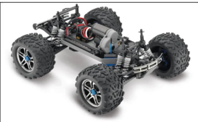
preliminary field tests with a prototype of all-terrain AGV based on a 1:8 scale radio-controlled vehicle (E-Maxx Brushless Model 3908, Traxxas, USA) and called "RobCat" (Figure 1). However, in these actual conditions, it was difficult to precisely control the
timing and the intensity of the pilot's actions on RobCat's commands during the airborne phase of manually controlled jumps (Figure 2). Moreover, the necessary wide field of view (around 10 m) of the high speed camera that recorded jumps drastically reduced measurements precision, preventing a complete validation of the mechanical model (Davis et al., 2012). There was thus a need of careful experiments in controlled laboratory conditions for verifying the mechanical model of pitch control and precisely quantifying its parameters before
implementing the model into RobCat's command.
2 MATERIAL &METHODS
The material (test bench) and the experiments presented in this section rely on a mechanical model of pitch control described below. This 2-D model allows the decomposition of RobCat's movements during any ballistic phase in two parts:
§ The parabolic translation of RobCat's CoM (G);
§ The pitch rotation of RobCat system (chassis plus wheels) around its centre of mass.
2.1 Mechanical model of pitch control
According to the mechanical model used for
analysing and explaining motocross jumps (Vaslin et al. 2011), RobCat system can be roughly
decomposed into (i) a rigid chassis (mass: mC, centre
of mass: GC, matrix of inertia: [JChassis]) mounted on
(ii) four identical wheels, with the same mass (mi)
and matrix of inertia ([JOi]), and which centres of
mass are assumed to be located at their respective centres of rotation (Oi) and at the distance GOi from
RobCat's CoM (G).
As a consequence of the law of movement composition, RobCat's pitching movements during Figure 1: RobCat (E-Maxx Brushless Model 3908,
Traxxas, USA).
Figure 2: Sequential view of an actual in-field jump with RobCat. The change in RobCat’s pitch attitude at the end of the ballistic phase was induced by an acceleration of its wheels by the pilot.
the airborne phase of an actual jump can be analysed by hanging the vehicle on a horizontal axis passing through its centre of mass. Then, the angular momenta of RobCat's elements had to be defined:
§
The angular momentum of RobCat's chassis (without wheels) with respect to its own CoM (GC) can be written:𝜎"#$%%&% = [𝐽"#$%%&%]𝜔, (1)
assuming that RobCat system is perfectly rigid so that the angular velocity of the chassis is the same as that of the whole system:
𝜔"#$%%&% = 𝜔, (2)
§
The total angular momentum of the four wheels with respect to their respective centres of mass (Oi) is given by:𝜎-#../%= [𝐽0&]
1
&23
𝜔4 (3)
§ According to its definition, the total barycentric angular momentum of RobCat system can be expressed with respect to RobCat's CoM (G):
𝜎5(789"$:)= 𝜎5("#$%%&%)+ 𝜎5(-#../%) (4)
As stated by Eq. 4, the angular momenta of RobCat's chassis (Eq. 1) and wheels (Eq.3) around their respective centres of mass must be expressed with respect to the CoM of RobCat system, using Koenig's First Theorem:
𝜎5 "#$%%&% = 𝐽"#$%%&% 𝜔,+ 𝐺𝐺"∧ 𝑚"𝑣"∗ (5) and: 𝜎5(-#../%)= [𝐽0&] 1 &23 𝜔4+ 𝐺𝑂& 1 &23 ∧ 𝑚&𝑣&∗ (6) where:
§ mC and mi are the masses of the chassis and of
one wheel, respectively;
§ 𝑣"∗ = 𝑣 𝐺"/𝑅∗ is the relative linear velocity
of the CoM of RobCat's chassis (GC) in
RobCat's barycentric reference frame (R*); § 𝑣&∗= 𝑣 𝑂
&/𝑅∗ is the relative linear velocity
of the wheel CoM - assumed to be located at the centre of rotation (Oi) of each of the four
wheels - in RobCat's barycentric reference frame (R*);
§ R* is RobCat's barycentric reference frame: its origin is RobCat's CoM (G) and its axes remain parallel to those of the terrestrial Galilean reference frame (R0).
The total barycentric angular momentum of RobCat system can be thus written:
𝜎5(789"$:)= 𝜎5Σ+ 𝜎-#../% (7) or: 𝜎5(789"$:)= [𝐽𝐺Σ]𝜔,+ [𝐽0&] 1 &23 𝜔4 (8) with:
𝐽5, = 𝐽"#$%%&% + 𝑚"𝐺𝐺"F+ 𝑚&𝐺𝑂&F 1
&23
(9) The interest of the expanded form of Eq. 8 is to express the total barycentric angular momentum of RobCat system as a function of the angular
velocities of the whole system (wS) and of its wheels
(wi). As these angular velocities could not be
precisely measured during actual experiments in the field (Davis et al., 2012), we decided to build a specific test bench (see below) allowing us to conduct laboratory experiments in a controlled environment.
2.2 Inertial parameters
Considering their importance in Eq. 8 and in further calculations, the geometric and inertial parameters of all RobCat's elements (mC, mi, GOi, GGC, [JOi],
[JChassis], [JGS]) had to be measured or calculated for
exploiting both the experiments on the pitch test bench and the future ones on the field. Inertial parameters of RobCat's elements (Table 1) have been determined in specific experiments (i. e. weighing and pendular oscillations).
Table 1: Inertial parameters of RobCat’s elements.
Wheel System
Mass (kg) 0.303 5.160
Moment of inertia (kg.m²) 0.001 0.204
2.3 Test bench
For simulating RobCat's movement during an airborne phase in safe laboratory experiments, a specific test bench has been built with aluminium frames and two tempered glass sides (Figure 3).
MCG 2016 –Vichy, France, October 5-6th, 2016
P a g e
|
4
Both glasses have been drilled in their middle in order to support a transversal axis that was mounted on two ball bearings. Theoretically, according to the above equations, RobCat had to be hanged on a transversal axis passing through its CoM in order to cancel the translation of this point and to focus measurements on the rotations of RobCat's chassis and wheels. As this could not practically be done without impairing its chassis, RobCat has been slightly modified with added materials (i.e. a small mass adjusted with threaded rods and nuts) so that the transversal axis of the test bench could pass through the CoM of the new RobCat system.
The frame and the materials of the test bench had been chosen for allowing the recording of RobCat's movements in its sagittal plane with a high speed camera (AOS S-Motion, AOS Technologies AG, Switzerland). The camera was placed on the right side of the test bench, so that its optical axis was aligned with the transversal y-axis of the test bench.
2.4 Experiments
The vehicle used in this study was originally equipped with hollow rubber tyres filled with foam inserts instead of pressurized air. During preliminary experiments on the test bench, it appeared that these tyres bulged at high rotation speeds. It was
hypothesized that this phenomenon should change the moments of inertia and thus the angular momenta of the wheels. In order to verify this hypothesis and to quantify the bulging effect on the
experimental results, we decided to build four rigid wheels having almost the same mass (0.335 kg) and moment of inertia (0.00135 kg.m²) as the non-deformed original ones, and to compare the results obtained with these two types of wheels.
Two sets of six trials each have been then performed: one with RobCat equipped with its original rubber tyres, and one with the rigid wheels. In each trial, RobCat's initial angular velocity was null, and the throttle was continuously pushed until reaching the power level (15%, 20%, 30%, 40%, 50% or 60 %) defined for this trial. No test was made over 60% of the power level because the intense vibrations generated at these levels could have damaged the test bench or the vehicle.
When the experimenter visually estimated that RobCat was rotating around its transversal axis at a steady angular velocity, the movements of RobCat's chassis and wheels were recorded with the high speed camera at 500 fps (1280 x 1024 pixels, shutter exposure time: 250 µsec) during the last 2.6 seconds of the trial. This duration was imposed by the size of the hard memory embedded in the camera (1.3 Gb).
All the video recordings have been manually processed using Motion Track software (Vannier Photelec, France). The 2-D positions of markers fixed on RobCat’s chassis and on the rims and axles of the right wheels were collected and expressed with respect to the origin (G) of the barycentric reference frame. These data were used to compute the angular velocities and the angular momenta of the system and of the front and rear wheels,
assuming that the right and left wheels had the same angular velocities.
3 RESULTS & DISCUSSION
The angular momenta of the four wheels, the chassis and the whole system have been computed in all trials (Figure 4). As, in each trial, the initial angular velocities of RobCat’s wheels and chassis were null, the initial angular momentum of the system was also null, and it should remain null all along the trial. The initial values and the drift of RobCat’s angular momentum on all the graphs in Figure 4 showed that this assumption was not true in both experiments with original tyres and rigid wheels. These results indicated that external forces (e.g. bearings friction, air resistance) could have acted on different parts of the system during experiments. This led us to make further measurements in order to evaluate these forces.
Figure 3: RobCat at rest in the test bench. Reference frames and variables used in the model are indicated.
The results of these second experiments showed that the torque due to bearings friction increased along a 2nd order polynomial relationship with respect to RobCat’s angular velocity (Figure 5). This force was mainly responsible of the drift of angular momenta of RobCat's elements. However, it will desappear during the airborne phase of actual jumps, because in these latter conditions RobCat will not be physically hanged on a transversal axis passing through its centre of mass.
The relationship between the angular velocities
of the system and its wheels was almost linear (Figure 6). Although this latter result involved both effects of bearing friction and air resistance, it meant that RobCat's angular velocity (wS) was almost
proportional to that of its wheels (wi), which could
be expected from Eq. 8. As this equation was based on the assumption that air resistance could be neglected during the airborne phase, this result validated this hypothesis.
Although RobCat's suspensions were rigidly locked during all trials, the graphs with original tyres
Figure 4: Total (blue) and partial angular momenta of RobCat's system (red) and wheels (yellow) equipped with rubber tyres (left column) or solid wheels (right column) during selected trials performed on the test bench at 15% (first line), 20% (second line), 40% (third line) and 60% (last line) of the engine power.
MCG 2016 –Vichy, France, October 5-6th, 2016
P a g e
|
6
showed increasing oscillations over 30% of engine power (Figure 4: left graphs). As this phenomenon almost disappeared with rigid wheels (Figure 4: right graphs), it was attributed to tyres bulging at high rotation speeds. Indeed, the high oscillation frequency corresponded to the angular velocity of the wheels and was generated by an excentric displacement of wheels CoM due to tyres bulging. The low oscillation frequency was attributed to an oscillation of the chassis induced by the out-of-balance rotation of the wheels.
Unlike the friction force identified above, these oscillations will surely exist in actual jumps with original tyres. However, they probably will be of less importance because airborne phases will be much shorter - usually less than 1 second - than the experiments on the test bench, and they do not influence the principle of angular momentum conservation used in the model of pitch control.
4 CONCLUSIONS
RobCat is a 1:8 scale radio-controlled four-wheeled high speed mobile robot equipped with a control device allowing to accelerate or to brake the wheels. This vehicle had been previously used for testing the possibility of correcting its pitch angle during the ballistic phases of actual jumps generated after rolling on a launch pad at high speed. However, the mechanical model of pitch control still had to be carefully verified in laboratory experiments. Two series of trials have been realized on a specific test bench in which RobCat was hanged on a transversal axis passing through its CoM. In each series, RobCat was equipped either with its original hollow rubber tyres or with solid wheels having equivalent inertial parameters. Although rubber tyres induced high and low oscillation frequencies of the system, the results of these experiments validated the mechanical model of angular momentum conservation of RobCat during an airborne phase and the feasibility of controlling RobCat's orientation around its pitch axis by accelerating or braking its wheels. This model can now confidently be implemented into RobCat's command for correcting its pitch attitude and velocity during any ballistic phase.
Compared to the lizard-like tail solution used in previous studies, the continuous rotation of RobCat's wheels - allowed by the central engine - provides a much higher dynamic moment than the limited half-turn rotation of a lizard-like tail. Moreover, RobCat's solution is simpler and lighter than the lizard-like tail as it does not require any additional onboard mechanism or actuator.
The conclusions of this experimental study are highly encouraging for building agile mobile robots able to roll at high velocities on irregular grounds and that will combine the speed of aerial drones with the large autonomy and interaction capacity of terrestrial robots.
ACKNOWLEDGEMENT
The authors wish to thank the LabEx IMobS3 (Université Clermont Auvergne, France) for supporting this project, and the students of SIGMA Clermont and UCA who participated in the successive experiments with RobCat.
Figure 6: Relationship between the angular velocities of RobCat’s wheels and chassis.
Figure 5: Relationship between RobCat’s angular velocity and bearings torque friction.
REFERENCES
Chang-Siu, E., Libby, Th., Tomizuka, M., Full, R.J.,2011. A Lizard-Inspired Active Tail Enables Rapid Maneuvers and Dynamic Stabilization in a Terrestrial Robot, Proc. IEEE/RSJ International Conference on
Intelligent Robots and Systems (IROS), San Francisco,
CA, USA, Sept. 25th-30th, 1887-1894.
Davis, M., Gouinaud, Ch., Fauroux, J.-Ch., Vaslin, Ph. 2011a. Modélisation du comportement en roulis d'un véhicule capable d'auto-retournement en phase balistique. 20ème Congrès Français de Mécanique
(CFM 2011), Besançon (France), 29 août – 2 sept. Davis, M., Gouinaud, Ch., Fauroux, J.-Ch., Vaslin, Ph.,
2011b. A Review of Self-Righting Techniques for Terrestrial Animals. International Workshop on
Bio-inspired Robots, Ecole des Mines de Nantes (France),
April 6th - 8th.
Davis, M., Vaslin, Ph., Fauroux, J.-Ch., Gouinaud, Ch., Ju, L., 2012. Experimental Evaluation of the Pitch Angle Righting Capabilities of a High Speed Terrestrial Vehicle in Ballistic Phase. Proceedings of the joint
XIth International Conference on Mechanisms and
Mechanical Transmissions (MTM) and the International Conference on Robotics (Robotics’12),
Clermont-Ferrand (France), Applied Mechanics and
Materials (Zürich: Trans Tech Publications), 162:
57-66.
Fauroux, J.-Ch., Chapelle, F., Bouzgarrou, B.-C., Vaslin, Ph., Krid, M., Davis, M., 2015. Mechatronic Design of Mobile Robots for Stable Obstacle Crossing at Low and High Speeds, pp. 567-630. In: Handbook of
Research on Advancements in Robotics and Mechatronics (2 vol.), Editor: Maki K. Habib,
Hershey (Pennsylvania, USA): IGI Global, 993 p. Galli, J.R., 1995. Angular momentum conservation and
the cat twist, The Physical Teacher, 33: 404-407. Kessens, C., Smith, D., Osteen, P., 2012. A Framework
for Autonomous Self-Righting of a Generic Robot on Sloped Planar Surfaces, Proc. IEEE International
Conference on Robotics and Automation (ICRA),
Saint-Paul, MN, USA, May 14th-18th, 4724-4729. O’Halloran, D., Wolf, A., Choset, H., 2005. Design of a
high-impact survivable robot, Mechanism and
Machine Theory, 40: 1345–1366.
Schmidt-Wetekam, C., Zhang, D., Hughes, R., Bewley, T., 2007. Design, optimization, and control of a new class of reconfigurable hopping rovers, Proc. 46th IEEE
Conference on Decision and Control, New Orleans,
LA, USA, Dec. 12th-14th, 5150-5155.
Schmidt-Wetekam, C., & Bewley, T., 2011. The design of an arm suspension mechanism for an underactuated single legged hopping robot, Proc. IEEE International
Conference on Robotics and Automation, 5529-5534.
Vaslin, Ph., Pouzols, V., Gouinaud, Ch., Fauroux, J.-Ch., Deleplanque, S., Davis, M. 2011. Contrôle du tangage d'un véhicule en phase balistique. 20ème Congrès Français de Mécanique (CFM 2011), Besançon
(France), 29 août – 2 sept.
Weng, Z., & Nishimura, H., 2000. Final-state control of a two-link cat robot by feed forward torque inputs, Proc.
6th International Workshop on Advanced Motion
Control, 261-269.
Yap, H. E., & Hashimoto, S., 2013. Dynamic step traverse of a two-wheeled mobile robot, International Journal
MCG 2016 –Vichy, France, October 5-6th, 2016