Perfluoroaryl-Elemental Sulfur S
N
Ar Chemistry in Covalent
Triazine Frameworks with High Sulfur Contents for
Lithium–Sulfur Batteries
Sang Hyun Je, Hyeon Jin Kim, Jiheon Kim, Jang Wook Choi,* and Ali Coskun*
In order to address the challenges associated with lithium–sulfur batterieswith high energy densities, various approaches, including advanced designs of sulfur composites, electrolyte engineering, and functional separators, are lately introduced. However, most approaches are effective for sulfur cathodes with limited sulfur contents, i.e., <80 wt%, imposing a significant barrier in realizing high energy densities in practical cell settings. Here, elemental sulfur-mediated synthesis of a perfluorinated covalent triazine framework (CTF) and its simultaneous chemical impregnation with elemental sulfur via SNAr chemistry are demonstrated. SNAr chemistry facilitates the dehalogena-tion and nucleophilic addidehalogena-tion reacdehalogena-tions of perfluoroaryl units with nucleo-philic sulfur chains, achieving a high sulfur content of 86 wt% in the resulting CTF. The given sulfur-impregnated CTF, named SF-CTF, exhibits a specific capacity of 1138.2 mAh g−1 at 0.05C, initial Coulombic efficiency of 93.1%, and capacity retention of 81.6% after 300 cycles, by utilizing homogeneously distributed sulfur within the micropores and nitrogen atoms of triazine units offering high binding affinity toward lithium polysulfides.
Dr. S. H. Je, H. J. Kim, J. Kim, Prof. J. W. Choi, Prof. A. Coskun Graduate School of Energy
Environment, Water, and Sustainability (EEWS)
Korea Advanced Institute of Science and Technology (KAIST) 291 Daehak-ro, Yuseong-gu, Daejeon 34141, Republic of Korea E-mail: [email protected]; [email protected] Prof. J. W. Choi
School of Chemical and Biological Engineering and Institute of Chemical Processes
Seoul National University
1 Gwanak-ro, Gwanak-gu, Seoul 08826, Republic of Korea Prof. A. Coskun
Department of Chemistry University of Fribourg
Chemin du Musée 9, Fribourg 1700, Switzerland
thus, there is a growing interest in the scientific community for the direct utiliza-tion of elemental sulfur toward high value applications,[2] and Li–S batteries are
well-aligned along such direction. There are, however, still significant challenges yet to be tackled in Li–S batteries; upon lithia-tion, sulfur transforms to soluble long-chain lithium polysulfides (Li2Sn, n = 4–8)
in electrolytes, leading to severe capacity loss over cycling.[3] In addition, sulfur
is also electrically/ionically insulating, imposing substantial resistance in dis-charge–charge process.
Most available approaches to address these shortcomings engage either physical or chemical confinement of sulfur into various hosts. In the case of physical con-finement, various types of porous mate-rials with high specific surface areas and pore volumes have been employed; molten sulfur was introduced into mesoporous carbons,[4] graphene oxide,[5] carbon nanotubes,[6] conducting
polymers,[7] metal-organic frameworks (MOFs),[8] covalent
organic frameworks (COFs),[9] and porous organic polymers[10]
via melt diffusion at around the melting point of sulfur (≈155 °C). Although these composites showed improved cycling performance compared to the simple mixtures of sulfur and conductive agents, polysulfide dissolution into the electrolyte is still difficult to completely eliminate mainly due to the lack of strong interactions between the pore surfaces and elemental sulfur or Li-polysulfides, especially at high sulfur contents (i.e., >60 wt%). In addition, this template-assisted strategy requires multistep material synthesis including template generation and sulfur diffusion, in which case the sulfur loading is also limited by the intrinsic pore volume of the host materials.
Chemical confinement of elemental sulfur, in principle, could address these issues. Polymer–sulfur composites can be obtained by the ring opening of elemental sulfur to a linear diradical form, which can undergo radical insertion reactions with various organic monomers and polymers[11] bearing either
unsaturated hydrocarbons[2b,12] or ArH[13] and ArSH[14]
func-tionalities to form stable CS bonds. In this direction, Pyun and co-workers demonstrated a direct copolymerization approach that involves the reaction of elemental sulfur with small aryl-ethenyl[15] or arylethynyl[16] monomers via radical insertion
mechanism at elevated temperatures. Notably, this “inverse vul-canization” approach showed a great potential for achieving not only high sulfur contents up to 90 wt% but also the formation
1. Introduction
Lithium–sulfur (Li–S) batteries have emerged as viable alterna-tives to current commercial lithium ion batteries (LIBs), espe-cially targeting medium- and large-scale applications because of their unparalleled theoretical energy density in gravimetric consideration (i.e., 2600 Wh kg−1).[1] Sulfur is among the most
abundant elements worldwide as it is mainly being produced as a by-product from the purification of natural gas and oil. This involuntary production of sulfur leads to global supply surplus;
http://doc.rero.ch
Published in "Advanced Functional Materials 27 (47): , 2017"
which should be cited to refer to this work.
of long polymeric sulfur chains between ethenyl groups. More recently, Park and co-worker reported[14b] elemental sulfur
insertion into crystalline trithiocyanuric acid via radical inser-tion reacinser-tion to ArSH moieties. These approaches achieved increased sulfur contents above 70 wt%, along with robust anchoring sites to elemental sulfur. It is, however, important to note that as these approaches involve the crosslinking of small organic monomers with elemental sulfur, the detachment of sulfur from organic monomers followed by the dissolution of Li-polysulfides or organic monomers into the electrolytes could still occur during the repeated charge–discharge cycles, thus significantly affecting their cycling performance. In addition, these copolymers are electrically insulating.
The concept of elemental sulfur-mediated polymerization which involves in situ formation of a fully π-conjugated 2D polymer network with sulfur being simultaneously attached
to the polymer backbone was recently demonstrated.[13]
Importantly, the formation of conjugated polymer network bearing heteroatoms not only facilitates electron transport, but also effectively suppresses the dissolution of Li-polysulfides utilizing their high binding affinity toward the heteroatoms located within the micropores. Although this approach allowed sulfur contents of 62 and 72 wt% by involving CH and CSH radical insertion reactions, respectively, the given crosslinking chemistry of sulfur does not permit further increase in the sulfur content. Thus, it is highly desirable to introduce new chemistries to achieve high sulfur contents beyond radical insertion reaction, while forming a conducting polymer net-work containing multiple binding sites, i.e., heteroatoms. In fact, high sulfur content turned out to be very critical to achieve high volumetric energy density of Li–S batteries.[1b]
In order to address the aforementioned issues, we turned our attention to the reactive intermediates originating from the ring opening of elemental sulfur. Elemental sulfur can undergo ring opening at elevated temperatures to yield either radicalic or ionic intermediates. Therefore, the judicious choice of the organic monomer/polymer backbone could, in principle, engage either of these reactive intermediates to form stable CS bonds. While the majority of polymer–sulfur composites used for sulfur cathodes relied on radicalic intermediates, it has been demonstrated that ionic intermediates of sulfur can pro-mote the trimerization of aryl cyanides to form covalent tria-zine frameworks (CTFs).[13] In an effort to utilize these ionic
intermediates to realize high sulfur contents, we envisioned the idea of employing nucleophilic aromatic substitution reac-tion (SNAr) between perfluoroaryl units and elemental sulfur to
increase the sulfur content significantly while achieving in situ synthesis of a fully conjugated polymer backbone.
SNAr is a fascinating chemistry for the direct
functionaliza-tion of electron-deficient aromatic molecules substituted with electron-withdrawing groups, such as nitro, chlorine, cyano, or fluorine; electron deficiency of aromatic core promotes the reactivity of the corresponding arenes toward nucleophiles.[17]
In particular, SNAr reactions involving perfluoroaryls have
been widely utilized for the development of various mate-rials, such as organomimetic cluster nanomatemate-rials,[18]
photo-switches,[19] peptide stapling with nucleophiles,[20] or fluorine
itself to form polyfluorobenzenes in organic solvents.[21] The
reactivity of perfluoroaryl compounds originates from their
strongly polarized electron distributions toward the formation of electron-deficient aromatic cores, which enables both dehalo-genation and nucleophilic addition reactions under mild con-ditions. While the SNAr reaction between perfluoroaryls and
thiol functionality is known,[20] to the best of our knowledge,
there is no report describing the direct reaction of elemental sulfur with perfluoroaryl monomers. Here, we report on the elemental sulfur-mediated synthesis of a CTF, namely SF-CTF, by promoting the trimerization of perfluorinated aryl cyanides while sulfur is simultaneously impregnated to the CTF back-bone via perfluoroaryl-elemental sulfur SNAr chemistry. This
approach enabled homogeneous distribution of sulfur within the π-conjugated framework while the sulfur contents reach up to 86 wt%. Also, the binding sites, triazine moieties, located within the micropores of SF-CTF effectively mitigate the dis-solution of Li-polysulfides. When tested as a cathode material in Li–S batteries, the given SF-CTF electrode showed good electrochemical performance, such as specific capacity of 1138.2 mAh g−1 at 0.05C, 93.1% initial Coulombic efficiency
(ICE), and 81.6% capacity retention at 1C for 300 cycles. These results suggest that SNAr chemistry can be beneficially adopted
for the preparation of sulfur-embedded polymer networks to achieve highly robust cycling performance of sulfur cathodes bearing high sulfur contents (>80 wt%).
2. Results and Discussion
CTFs are emerging class of porous organic polymers with high thermal/chemical stability, high surface areas, and good elec-trical conductivity.[22] CTFs are usually synthesized based on
the trimerization of aryl cyanides under ionothermal conditions using ZnCl2 as both reaction medium and catalyst.[22] More
recently, it has also been reported that CTFs can be synthesized using strong acids[23] or elemental sulfur.[13] In particular, the in
situ synthesis of CTFs using elemental sulfur can bring unique advantages for their use as sulfur cathodes, such as homoge-neous distribution of sulfur within the micropores of CTFs and the formation of π-conjugated framework for improved electrical conductivity. In addition, triazine units could serve as high affinity binding sites for capturing Li-polysulfides, thus mitigating their dissolution into the electrolyte.
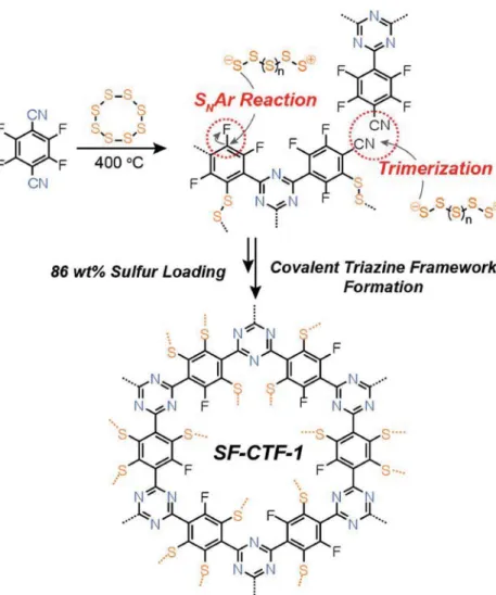
The synthesis of SF-CTF-1 was achieved (Figure 1) in a one-pot reaction by simply reacting elemental sulfur with tetrafluorophthalonitrile at 160 °C and subsequently at 400 °C at different nitrile:sulfur weight ratios of 1:1, 1:3, and 1:5. The first heating step at 160 °C was employed to form a homo genous mixture of molten linear sulfur chains and the mono mer. The subsequent heat treatment at 400 °C facilitated the formation of linear ionic sulfur species that not only mediate the forma-tion of CTF through the trimerizaforma-tion of arylcyanide, but also act as nucleophiles for the chemical impregnation of sulfur via SNAr reaction. As a reference without sulfur impregnation,
F-CTF-1 was also prepared following the previous literature under ionothermal conditions using ZnCl2.[24]
In order to assess the elemental compositions of F-CTF-1 and SF-CTFs with varying amounts of sulfur loading, elemental analysis (EA) was carried out (Table 1). The sulfur content grad-ually increased from 67 to 98 wt% with increasing sulfur ratio
from 1:1 to 1:5 in the reaction mixture. The EA analysis enabled us to retrieve fluorine contents from other element contents in Table 1 and clearly revealed the decreased content of fluo-rine following the sulfur impregnation: in contrast with that of F-CTF-1 (33.6 wt%), SF-CTF-1 (1:1) contains only 7.72 wt% of fluorine. The fluorine contents become much lower for both SF-CTF-1 (1:3) and SF-CTF-1 (1:5), which are less than 2 wt%. These decreased fluorine contents, in turn, reflect the high efficiency of sulfur impregnation via SNAr reaction when
com-pared to either CH or CSH insertion reactions. The high
efficiency of sulfur impregnation is also sup-ported by much higher sulfur contents of SF-CTF-1s; at the same monomer:sulfur ratio of 1:3 in the synthesis, SF-CTF-1 contains 86 wt% of sulfur, whereas S-CTF-1, in which the sulfur impregnation was achieved solely by radicalic C-H insertion, contains only 62 wt%.
Fourier transform infrared spectroscopy (FT-IR) analysis was carried out (Figure 2a) to investigate the formation of SF-CTF-1s. For all the SF-CTF-1 samples, we consistently observed the peak at 1630 cm−1 corresponding
to the triazine cores.[22] Nonetheless, some
trait of triazine became weakened during the polymerization involving the sulfur impregnation; the characteristic stretching band of v(CN) located at 2218 cm−1 was
partly remained in SF-CTF-1 (1:1), whereas it completely disappeared in both SF-CTF-1 (1:3) and SF-CTF-1 (1:5). This phenomenon implies that higher sulfur contents are crit-ical for efficient polymerization of SF-CTF-1s. In order to evaluate the crystallinity of SF-CTF-1s, powder X-ray diffraction (PXRD) analysis was conducted (Figure S1, Sup-porting Information). This analysis revealed the amorphous nature of SF-CTF-1s and also the presence of crystalline sulfur domains trapped within the polymer networks as com-monly observed in in situ sulfur-polymerized compounds. The additional peak of SF-CTF-1 (1:1) at 17° indicates incomplete polymeriza-tion at this sulfur loading. The incomplete polymerization was further supported by the thermogravimetric analysis (TGA) profile of SF-CTF-1 (1:1) performed under N2
atmos-phere (Figure 2b); a substantial and continuous mass loss was observed in the range of 150 to 800 °C.
In contrast, SF-CTF-1 (1:3) and SF-CTF-1 (1:5) exhibited clearly distinct profiles such that the mass drops drastically at around 200 °C, reflecting the stable encapsulation of sulfur within the polymer networks via CS bonds. Based on the mass loss in the range of 200 to 350 °C, these two sulfur-rich polymers hold 86 and 99 wt% of sulfur, respectively, which are in good agreement with the results of the EA analysis. In this study, the sulfur contents obtained from TGA analysis were Figure 1. Synthetic scheme for the synthesis of SF-CTF-1s involving elemental sulfur-mediated
nitrile trimerization along with the simultaneous covalent attachment of elemental sulfur via SNAr chemistry.
Table 1. Elemental analysis of F-CTF-1, S-CTF-1, and SF-CTFs.
Samples Carbona) [wt%] Hydrogena) [wt%] Nitrogena) [wt%] Sulfura) [wt%] Total
F-CTF-1 47.62 (47.81) 2.96 (0) 15.82 (18.58) 0 (0) 66.4
S-CTF-1 33.19 (18.75) 0.77 (0.78) 3.76 (5.47) 61.91 (75.00) 99.63
SF-CTF-1 (1:1) 19.42 (24.01) 0.12 (0) 5.63 (7.00) 67.11 (50.00) 92.28 SF-CTF-1 (1:3) 5.28 (12.01) 0.05 (0) 1.51 (3.50) 91.72 (75.00) 98.56 SF-CTF-1 (1:5) 0.33 (8.00) 0.03 (0) 0.07 (1.16) 98.42 (83.00) 98.85
a)The values reported in parenthesis are theoretical ones.
used for the evaluation of specific capacities. The bonding nature of sulfur in the SF-CTF-1s was elucidated (Figure 2c) by dispersive Raman analysis. The peak observed at 464 cm−1 was assigned to SS stretching band along with the CS stretching bands at 234 and 162 cm−1.[2c] Moreover, the presence of D and
G bands located at 1446 and 1535 cm−1, respectively, indicates
the graphitic nature of the CTF hosts. Notably, the intensities of the D and G bands were conspicuously lower for SF-CTF-1 (1:1) than for SF-CTF-1 (1:3) and SF-CTF-1 (1:5), once again because of the low-degree of polymerization of SF-CTF-1 (1:1).
The detailed bonding nature of F-CTF-1 and SF-CTF-1s was also studied with X-ray photoelectron spectroscopy (XPS), as displayed in Figures S2–S4 (Supporting Information) for C1s, N1s, and S2p, and Figure 2d for F1s.[24] The C1s core-level
spec-trum of F-CTF-1 revealed (Figure S2a, Supporting Information) three peaks located at 284.6, 286.2, and 287.8 eV, which were assigned to carbon atoms of the phenyl, triazine, and the semi-ionic peak of C-F, respectively. While the peaks originating from the phenyl and triazine moieties were preserved in all the SF-CTF-1 samples, the intensity of the C-F peak at 287.8 eV gradually decreased and ultimately disappeared with increasing sulfur content. The decrease in the intensity of C-F peak was also accompanied by the emergence of C-S peak at 285.6 eV, thus proving that most of the C-F bonds were replaced with C-S bonds through SNAr reaction. N1s spectra of SF-CTF-1s showed
two characteristic peaks at 398.7 and 400.5 eV, corresponding to the triazine rings[25] and terminal nitrile functionality,[26]
respectively. The significant decrease in the intensity of nitrile peak in SF-CTF-1 (1:3) and (1:5) points to the efficient trim-erization of nitrile moieties to form the CTF backbones. The
S2p XPS spectra of SF-CTF-1 (1:3) and (1:5) revealed four peaks with binding energies of 163.7, 164.5, 164.8, and 165.8 eV. In the case of SF-CTF-1 (1:1), these four peaks were found to overlap at 163.7 and 164.8 eV and are assigned to the SS bonding originating from both CSnC (n = 5–6) chain[11c,27]
and elemental sulfur,[8b] as also observed in
the PXRD analysis. On the other hand, the peaks of SF-CTF-1 (1:3) at 163.7 and 164.8 eV were attributed to the SS bonding of ele-mental sulfur, whereas the largely overlapped peaks at 164.5 and 165.8 eV arise from CSnC (n = 5–6). Similarly, in the case
of SF-CTF-1 (1:5), more pronounced peaks at 163.7 and 164.8 eV were observed, indi-cating further developed short-chain organic sulfides and S-S bonding in residual ele-mental sulfur. The two peaks located at 687.2 and 688.3 eV in the F 1s spectra of F-CTF-1 and SF-CTF-1s were weakened significantly and ultimately disappeared in SF-CTF-1 (1:3; Figure 2d), thus further confirming the com-plete substitution of fluorine with sulfur via SNAr reaction.
The bulk scale morphology and atomic distribution of SF-CTF-1s were investigated (Figures S5 and S6, Supporting Informa-tion) using field-emission scanning electron microscopy (FE-SEM) and energy-dispersive X-ray spectroscopy (EDX). F-CTF-1 synthesized under ionothermal reaction con-ditions exhibited regular cubic morphologies with an average particle size of ≈700 nm. In contrast, SF-CTF-1s showed much smaller particle size in the range of 70–100 nm. The distinct particle sizes might be explained by the fact that the homog-enous molten sulfur–monomer mixture leads to a better disper-sion of the monomers and the formation of more fine particles during the in situ polymerization toward SF-CTF-1s compared to the molten mixture counterpart engaging ZnCl2. EDX
ele-mental mapping of SF-CTF-1s revealed (Figures S6–S10, Sup-porting Information) homogenous distributions of carbon, nitrogen, and sulfur atoms throughout the samples. Notably, the signals associated with the fluorine atoms have disappeared completely in both SF-CTF-1 (1:3) and SF-CTF-1 (1:5), recon-firming the complete fluorine substitution by sulfur.
The high sulfur contents and graphitic nature of SF-CTF-1s along with the presence of heteroatoms prompted us to investigate their performance as cathode materials in Li–S batteries. To this end, SF-CTF-1s were evaluated through gal-vanostatic measurements in CR2032 coin cells using Li metal as the counter/reference electrode. In detail, SF-CTF-1s were dispersed with conductive agent (super P), binder (PVDF) in
N-methyl-2-pyrrolidone (NMP) as a solvent with a mass ratio
of 60:30:10. The dispersions were then cast onto aluminum foil current collectors using the doctor-blade method. Note that 1.0 M lithium bis-trifluoromethanesulfonylimide (LiTFSI) in the solvent mixture of tetraethylene glycol dimethyl ether/1,3-diox-olane (TEGDME:DIOX = 0.33:0.67) was used as an electrolyte. In addition, LiNO3 (0.2 M) was added to the electrolyte solution
Figure 2. Structural analysis of SF-CTF-1s. a) FT-IR spectra of tetrafluorophthalonitrile and
SF-CTF-1s. b) TGA curves under N2 atmosphere. c) Raman spectra. d) F 1s XPS spectra of F-CTF-1 and SF-CTFs.
to stabilize the surface of Li metal. All electrochemical meas-urements were carried out in the voltage range of 1.8–2.7 V versus Li/Li+, and the current densities and specific capacities
of all SF-CTF-1s were attained based on the weight of sulfur only. In order to identify the optimal monomer:sulfur ratio, SF-CTF-1 (1:1), (1:3), and (1:5) were investigated under the given potential window. The sulfur mass loadings of SF-CTF-1s were ≈0.70 mg cm−2.
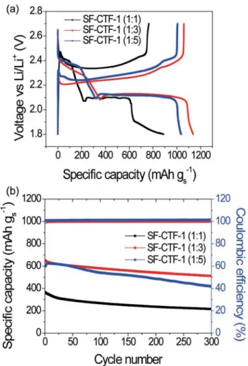
The first discharge–charge voltage profiles of SF-CTF-1s measured at 0.05C (50 mA g−1) are shown in Figure 3a. The first discharge capacities of SF-CTF-1 (1:1), (1:3), and (1:5) were 889.9, 1138.2, and 1037.8 mAh g−1, respectively. The abnor-mally small specific capacity of SF-CTF-1 (1:1), together with the additional discharging plateau in the range of 1.9–1.8 V, is attributed to the incomplete substitution reaction of tetrafluo-rophthalonitrile with sulfur and low degree of polymerization, which is also coherent with the XPS results in Figure 2d. By contrast, both SF-CTF-1 (1:3) and (1:5) exhibited discharge-charge profiles consistent with those of typical sulfur cathodes: two discharging plateaus at around 2.35 and 2.10 V, originating from the transformation of sulfur to higher-order lithium
polysulfide species (Li2Sn, n ≥ 4) and the subsequent
forma-tion of lithium sulfide (Li2S), respectively.[1a,4,5b,28] The ICEs of
93.1% and 96.9% of SF-CTF-1 (1:3) and (1:5) are remarkable, as ICE over 100% or far below 100% indicates significant shut-tling problem or lithium ion trapping, respectively.[14a]
In order to see the effect of sulfur content in SF-CTF-1s, their cycling performances were evaluated at 1C (1000 mA g−1) (Figure 3b). At this C-rate, SF-CTF-1 (1:1), (1:3), and (1:5) exhibited initial discharge capacities of 365.1, 637.3, and 598.9 mAh g−1, respectively. Notably, after 300 cycles, these electrodes preserved discharge capacities of 215.5, 520.1, and 418.4 mAh g−1, respectively, corresponding to 59.1%, 81.6%, and 69.9% capacity retentions with respect to their initial capacities. Especially, the capacity retention of SF-CTF-1 (1:3) is noticeable considering its sulfur content of 86.0 wt%. The slightly inferior cyclability of SF-CTF-1 (1:5) indicates that its sulfur content of 99.5 wt% is too high, exceeding the optimal value. The obtained ICE value and cycling performance imply that our SNAr approach for SF-CTFs can effectively stabilize
both sulfur and Li-polysulfides even at 86 wt% of sulfur content. In an attempt to demonstrate the effect of the SNAr reaction
on the electrochemical performance of the resulting SF-CTFs, the electrochemical properties of S-CTF-1 (1:3) based on the C-H insertion reaction were also analyzed together. Although both S-CTF-1 (1:3) and SF-CTF-1 (1:3) showed (Figure 4a) similar first discharge–charge voltage profiles, SF-CTF-1 (1:3) showed a higher first discharge capacity of 1138.2 mAh g−1
compared to that (1028.4 mAh g−1) of S-CTF-1, pointing to the fact that in the case of SF-CTF-1, a higher portion of sulfur participates in the reaction with Li ions even with the higher sulfur content. The high gravimetric capacity of SF-CTF-1 (1:3) also indicates the benefit of SF-CTF-1 in terms of volu-metric energy density. The cyclability of SF-CTF-1 (1:3) was also compared with that of S-CTF-1 (1:3) for 300 cycles at 1C and 2C (Figure S11, Supporting Information). The gravimetric capacities of SF-CTF-1 (1:3) after 300 cycles at 1C and 2C were 520.1 and 435.1 mAh g−1, which are higher than those (445.1
and 411.6 mAh g−1) of S-CTF-1 (1:3). Once again, the higher capacities of SF-CTF-1 (1:3) after prolonged cycles are ascribed to the efficient entrapment of sulfur through SNAr chemistry
as well as the stabilized Li-polysulfides via the heteroatoms available within the micropores of CTFs. A comparison with a composite of physically impregnated sulfur in CTF-1 (denoted as CTF-1/S@155 °C) verifies the usefulness of the CS bond formation via SNAr chemistry; CTF-1/S@155 °C contains only
34 wt% sulfur and also suffers from severe capacity decay over 50 cycles.[10]
SF-CTF-1 (1:3) also exhibited decent rate capability (Figure 4b). When the C-rate was increased from 0.1C to 0.2C, 0.5C, 1C, 2C, and 5C, 77.2%, 64.7%, 57.4%, 53.0%, 47.3%, and 33.7% of the discharge capacities were preserved, respectively, with respect to that (1138.2 mAh g−1) at 0.05C. Based on the rate capability that withstands high C-rates, the cycling performance of SF-CTF-1 (1:3) was evaluated at 1C, 2C, and 5C (Figure 4c). After 300 cycles, 520.1, 435.1, and 330.3 mAh g−1 were
main-tained at the given C-rates, respectively, corresponding to 81.6%, 82.4%, and 88.3% capacity retentions. The average CEs at those C-rates stayed over 99.0% throughout the cycling, reflecting high reversibility of SF-CTF-1 (1:3) during cycling. Figure 3. Electrochemical performance of SF-CTF-1s with varying sulfur
ratios. a) The first discharge–charge curves of SF-CTF-1s measured at 0.05 C in a voltage range of 1.8–2.7 V. b) Cycling performances and CE of SF-CTF-1s at 1C (1000 mA g−1) over 300 cycles.
The observed robust cycling performance at high C-rates is attributed to the conjugated structure of the CTF backbone that supports electric conductivity, while Li-polysulfide dissolution is largely suppressed by the high binding affinities of the heter-oatoms located in the inner surfaces of the micropores. More cycling data of SF-CTF-1 (1:3), together with those of S-CTF-1 (1:3), and the voltage profiles of SF-CTF-1 (1:3) at various C-rates are presented in Figures S11 and S12 in the Supporting Information, respectively.
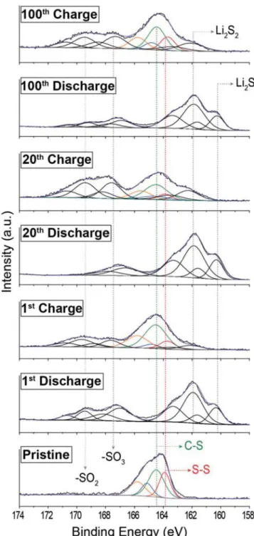
To elucidate the reversibility of SS bond formation during repeated discharge–charge cycles in SF-CTF-1, ex situ XPS analysis was performed on the SF-CTF-1 (1:3) electrodes at the
1st, 20th, and 100th cycles. As depicted in Figure 5, the S 2p spectrum of pristine electrode showed SS and CS bonds at 163.7 and 164.5 eV, respectively. In the first discharged state, the emergence of new peaks at 160.1 and 161.9 eV clearly verifies the formation of Li2S and Li2S2. When the cell was
charged again, the peaks at 163.7−164.5 eV reappeared, sug-gesting the reversible formation of sulfur–sulfur bonds within SF-CTF-1 (1:3). Notably, even when the cycle number reached
up to 100, the formation of the CSnC bond and the
lithium sulfides was observed consistently without any binding energy shift in the S 2p spectra, suggesting the excellent sta-bility of the polymer backbone and reversible formation of Figure 4. Electrochemical performance of SF-CTF-1 (1:3). a) Comparison of the first discharge–charge profiles of SF-CTF-1 (1:3) and S-CTF-1 (1:3).
b) Rate performance of SF-CTF-1 (1:3) evaluated at various C-rates. c) Cycling performance and Coulombic efficiencies of SF-CTF-1 (1:3) when meas-ured at 1C, 2C, and 5C over 300 cycles. 1C = 1000 mA g−1.
SS bonds during the repeated charge–discharge cycles. In particular, at each fully discharged state, the appearance of the polysulfide peaks located at 162.3 and 163.9 eV with similar intensities further implies the efficient inhibition of polysulfide dissolution.[14a] The additional peaks beyond 167 eV could be
explained by the formation of sulfone complex (SO2 or SO3)
arising from the degradation of electrolyte as also previously
observed by Hong and co-workers.[29] Ex situ Li 1s spectra in
Figure S13 (Supporting Information) further support the for-mation of Li2SOx at 55.9 eV. These findings indicate clearly that
electrolyte decomposition could significantly contribute to the capacity decay.[30] Thus, it is important to note that we reached
86 wt% sulfur content in SF-CTF-1 (1:3) with stable cycling performances by virtue of conductive polymer templates, but a slight capacity decay was inevitable due to the electrolyte decomposition.
3. Conclusion
In summary, we presented a new chemical approach, that is perfluoroaryl-elemental sulfur SNAr chemistry, to embed an
extraordinarily large amount (>80 wt%) of sulfur in CTFs. The given SNAr reaction involves nucleophilic ionic intermediates
from the ring-opening of elemental sulfur to facilitate in situ polymerization toward a sulfur-embedded polymer network in which a high content of sulfur is homogeneously distributed within the polymer network. The homogeneous distribution of sulfur, conjugated polymer backbone supporting electron transport, and heteroatoms with high binding affinities with Li-polysulfides all jointly result in exceptional electrochemical performance of SF-CTF-1 (1:3) when tested as a cathode mate-rial for Li–S batteries. Since the success of Li–S batteries lies in stable cycling of sulfur cathodes while securing a high sulfur content, SNAr chemistry is expected to be adopted for various
sulfur polymers where sulfur can maintain stable redox reac-tions over repeated cycling by taking advantage of covalent attachment to the conjugated polymer backbone. It is reminded that the competitiveness of Li–S battery technology in compar-ison with current LIBs is the high energy density, which can be achieved only when high sulfur content is included in the sulfur electrode. It is also anticipated that this new polymeriza-tion approach for the preparapolymeriza-tion of sulfur-embedded polymer networks with high sulfur loadings can be expanded to envi-ronmental applications such as heavy metal capture utilizing extended sulfur chain networks.
4. Experimental Section
Materials and Methods: All materials were purchased from
Sigma-Aldrich and used without further purification. FT-IR spectra were recorded on Nicolet iS50 FT-IR spectrometer using KBr pellet in the transmission mode and reported in reciprocal centimeter (cm−1). TGA was performed on a Shimadzu DTG-60A instrument by heating the samples at a rate of 10 °C min−1 under N2 atmosphere up to 800 °C. EA was carried out using FLASH 2000 (ThermoScientific). PXRD analysis was performed by using Rigaku D/MAX-2200 Ultima/PC from 5° to 80° at a scanning rate of 4° min−1. FE-SEM and EDX analyses were carried out using Magellan 400 manufactured by FEI. XPS was performed using K-alpha model on a Thermo VG Scientific XPS instrument. Raman spectra were obtained using ARAMIS dispersive-Raman instrument (Horiba Jobin Yvon) equipped with a 514 nm wavelength laser. The galvanostatic tests were performed using a WBCS 3000 battery cycler (Wonatech battery test machine, Korea).
Synthesis of the SF-CTF-1s with Varying Sulfur Ratio: Sulfur-substituted
CTFs (SF-CTF-1s) were synthesized by reacting tetrafluorophthalonitrile with elemental sulfur at different mass ratios between tetrafluorophthalo nitrile:sulfur (1:1, 1:3, 1:5).
Figure 5. Ex situ S 2p XPS spectra of SF-CTF-1 (1:3) at pristine, 1st, 20th,
and 100th cycles. All cells were measured at 1 C (1000 mA g−1) with 1 M LiTFSI in TEGDME/DOL (0.33:0.67 vol) as the electrolyte. Charged/dis-charged active materials were extracted in an argon-filled glove box and washed several times before analysis.
General Procedure for the Synthesis of SF-CTF-1s:
Tetrafluoro-phthalonitrile and elemental sulfur (0.2 g of tetrafluoroTetrafluoro-phthalonitrile and 0.6 g elemental sulfur used for SF-CTF-1 (1:3)) were homogenously grounded and charged in a pyrex ampoule (3 × 12 cm). Atmosphere of ampoule was replaced with argon gas and evacuated. Procedure was repeated for 3 times, and the ampoule was then kept under vacuum for 30 min and flame-sealed. The ampoule was transferred to a box furnace, and inside temperature was slowly increased to 160 °C for 2 h (rate: 1 °C min−1) and kept for 15 h. Temperature was subsequently increased to 400 °C over 2.5 h and kept at this temperature for additional 15 h. After cooling it down to room temperature, SF-CTF-1 (1:3) was obtained as black powder in quantitative yield. Resulting powder was used as prepared for further analysis and electrochemical tests.
Synthesis of F-CTF-1: F-CTF-1 was synthesized by following the
previously reported literature report.[24]
Electrochemical Characterization of SF-CTF-1s: CR2032-type coin cells
were used to evaluate the electrochemical properties of SF-CTF-1s. Electrodes were prepared by dispersing SF-CTF-1s with poly(vinylidene fluoride) (PVDF, Mw= 560 000, Aldrich) and Super P in a mass ratio of 60 (active): 30 (Super P): 10 (binder) in N-methyl-2-pyrrolidone (NMP, Junsei Chemical). These slurries were then cast onto aluminum foil current collectors (20 μm, Hohsen, Japan) using the doctor blade technique. Next, the coated electrodes were dried in a convection oven at 60 °C overnight. The CR2032 coin cells were assembled in an Ar-filled glove box with Li metal discs as both counter and reference electrodes, polypropylene separators (Celgard 2400), and electrolyte. The electrolyte was 1 M lithium bis(trifluoromethane)sulfonamide (LiTFSI, Aldrich) with 0.2 M of lithium nitrate additive (LiNO3, Aldrich) dissolved in the mixed solvents of tetraethylene glycol dimethyl ether (TEGDME, Aldrich) and 1,3-dioxolane (DIOX, Aldrich) in a volume ratio of 0.33:0.67. All electrochemical characterizations were carried out using a WBCS 3000 battery cycler (Wonatech, Korea) in the potential range of 1.8–2.7 V versus Li/Li+. The mass loadings of SF-CTF-1 electrodes were ≈0.70 mgsulfur cm−2, and the specific capacities were obtained based on the mass of sulfur only.
Supporting Information
Supporting Information is available from the Wiley Online Library or from the author.
Acknowledgements
S.H.J. and H.J.K. contributed equally to this work. The authors acknowledge the support by the Energy Efficiency & Resources Core Technology Program of the Korea Institute of Energy Technology Evaluation and Planning (KETEP), which is granted financial resources from the Ministry of Trade, Industry & Energy, Republic of Korea (20152020104870) and the National Research Foundation of Korea grant (NRF-2015R1A2A1A05001737). This research was supported by Basic Science Research Program through the National Research Foundation of Korea (NRF) funded by the Ministry of Education (2017R1A6A3A01005029 and 2017M1A2A2044477).
Conflict of Interest
The authors declare no conflict of interest.
Keywords
elemental sulfur, lithium–sulfur battery, nucleophilic aromatic substitution, porous organic polymer, trimerization
[1] a) A. Manthiram, Y. Fu, S.-H. Chung, C. Zu, Y.-S. Su, Chem. Rev.
2014, 114, 11751; b) J. W. Choi, D. Aurbach, Nat. Rev. Mater. 2016, 1, 16013; c) P. G. Bruce, S. A. Freunberger, L. J. Hardwick,
J.-M. Tarascon, Nat. Mater. 2012, 11, 19.
[2] a) S. H. Je, O. Buyukcakir, D. Kim, A. Coskun, Chem 2016,
1, 482; b) M. J. H. Worthington, R. L. Kucera, J. M. Chalker, Green Chem. 2017, 19, 2748; c) M. P. Crockett, A. M. Evans,
M. J. H. Worthington, I. S. Albuquerque, A. D. Slattery, C. T. Gibson, J. A. Campbell, D. A. Lewis, G. J. L. Bernardes, J. M. Chalker, Angew.
Chem. 2016, 128, 1746; Angew. Chem., Int. Ed. 2016, 55, 1714;
d) D. J. Parker, H. A. Jones, S. Petcher, L. Cervini, J. M. Griffin, R. Akhtar, T. Hasell, J. Mater. Chem. A 2017, 5, 11682; e) D. A. Boyd, Angew. Chem., Int. Ed. 2016, 55, 15486; f) M. Worthington, R. Kucera, I. Albuquerque, C. Gibson, A. Sibley, A. Slattery, J. Campbell, S. Alboaiji, K. Muller, J. Young, N. Adamson, J. Gascooke, D. Jampaiah, Y. Sabri, S. Bhargava, S. Ippolito, D. Lewis, J. Quinton, A. Ellis, A. Johs, G. Bernardes, J. M. Chalker,
Chem. - Eur. J. 2017, https://doi.org/10.1002/chem.201702871;
g) I. Gomez, O. Leonet, J. A. Blazquez, D. Mecerreyes,
ChemSu-sChem 2016, 9, 3419; h) A. Hoefling, Y. J. Lee, P. Theato, Macromol. Chem. Phys. 2017, 218, 1600303; i) J. J. Griebel, R. S. Glass, K. Char,
J. Pyun, Prog. Polym. Sci. 2016, 58, 90.
[3] a) Y. Yang, G. Zheng, Y. Cui, Chem. Soc. Rev. 2013, 42, 3018; b) L. Qie, C. Zu, A. Manthiram, Adv. Energy Mater. 2016, 6, 1502459.
[4] X. Ji, K. T. Lee, L. F. Nazar, Nat. Mater. 2009, 8, 500.
[5] a) L. Ji, M. Rao, H. Zheng, L. Zhang, Y. Li, W. Duan, J. Guo, E. J. Cairns, Y. Zhang, J. Am. Chem. Soc. 2011, 133, 18522; b) H. Wang, Y. Yang, Y. Liang, J. T. Robinson, Y. Li, A. Jackson, Y. Cui, H. Dai, Nano Lett. 2011, 11, 2644.
[6] a) J. Guo, Y. Xu, C. Wang, Nano Lett. 2011, 11, 4288; b) T. Xu, J. Song, M. L. Gordin, H. Sohn, Z. Yu, S. Chen, D. Wang, ACS Appl.
Mater. Interfaces 2013, 5, 11355.
[7] Y. Yang, G. Yu, J. J. Cha, H. Wu, M. Vosgueritchian, Y. Yao, Z. Bao, Y. Cui, ACS Nano 2011, 5, 9187.
[8] a) J. Zheng, J. Tian, D. Wu, M. Gu, W. Xu, C. Wang, F. Gao, M. H. Engelhard, J.-G. Zhang, J. Liu, J. Xiao, Nano Lett. 2014, 14, 2345; b) R. Demir-Cakan, M. Morcrette, F. Nouar, C. Davoisne, T. Devic, D. Gonbeau, R. Dominko, C. Serre, G. Férey, J.-M. Tarascon, J. Am. Chem. Soc. 2011, 133, 16154.
[9] H. Liao, H. Wang, H. Ding, X. Meng, H. Xu, B. Wang, X. Ai, C. Wang, J. Mater. Chem. A 2016, 4, 7416.
[10] H. P. Liao, H. M. Ding, B. J. Li, X. P. Ai, C. Wang, J. Mater. Chem. A
2014, 2, 8854.
[11] a) T. H. Hwang, D. S. Jung, J. S. Kim, B. G. Kim, J. W. Choi,
Nano Lett. 2013, 13, 4532; b) J. Wang, J. Yang, J. Xie, N. Xu, Adv. Mater. 2002, 14, 963; c) L. Xiao, Y. Cao, J. Xiao, B. Schwenzer,
M. H. Engelhard, L. V. Saraf, Z. Nie, G. J. Exarhos, J. Liu, Adv.
Mater. 2012, 24, 1176; d) J.-S. Kim, T. H. Hwang, B. G. Kim, J. Min,
J. W. Choi, Adv. Funct. Mater. 2014, 24, 5359.
[12] W. J. Chung, J. J. Griebel, E. T. Kim, H. Yoon, A. G. Simmonds, H. J. Ji, P. T. Dirlam, R. S. Glass, J. J. Wie, N. A. Nguyen, B. W. Guralnick, J. Park, Á. Somogyi, P. Theato, M. E. Mackay, Y.-E. Sung, K. Char, J. Pyun, Nat. Chem. 2013, 5, 518.
[13] S. N. Talapaneni, T. H. Hwang, S. H. Je, O. Buyukcakir, J. W. Choi, A. Coskun, Angew. Chem. 2016, 128, 3158; Angew. Chem., Int. Ed.
2016, 55, 3106.
[14] a) S. H. Je, T. H. Hwang, S. N. Talapaneni, O. Buyukcakir, H. J. Kim, J.-S. Yu, S.-G. Woo, M. C. Jang, B. K. Son, A. Coskun, J. W. Choi,
ACS Energy Lett. 2016, 1, 566; b) H. Kim, J. Lee, H. Ahn, O. Kim,
M. J. Park, Nat. Commun. 2015, 6, 7278.
[15] Y. Zhang, J. J. Griebel, P. T. Dirlam, N. A. Nguyen, R. S. Glass, M. E. Mackay, K. Char, J. Pyun, J. Polym. Sci., Part A: Polym. Chem.
2017, 55, 107.
[16] P. T. Dirlam, A. G. Simmonds, T. S. Kleine, N. A. Nguyen, L. E. Anderson, A. O. Klever, A. Florian, P. J. Costanzo, P. Theato, M. E. Mackay, R. S. Glass, K. Char, J. Pyun, RSC Adv. 2015, 5, 24718. [17] a) V. N. Charushin, O. N. Chupakhin, Mendeleev Commun. 2007,
17, 249; b) R. J. Armstrong, M. D. Smith, Angew. Chem. 2014, 126,
13036; Angew. Chem., Int. Ed. 2014, 53, 12822.
[18] E. A. Qian, A. I. Wixtrom, J. C. Axtell, A. Saebi, D. Jung, P. Rehak, Y. Han, E. H. Moully, D. Mosallaei, S. Chow, M. S. Messina, J. Y. Wang, A. T. Royappa, A. L. Rheingold, H. D. Maynard, P. Kral, A. M. Spokoyny, Nat. Chem. 2017, 9, 333.
[19] R. Travieso-Puente, S. Budzak, J. Chen, P. Stacko, J. T. Jastrzebski, D. Jacquemin, E. Otten, J. Am. Chem. Soc. 2017, 139, 3328. [20] A. M. Spokoyny, Y. Zou, J. J. Ling, H. Yu, Y. S. Lin, B. L. Pentelute,
J. Am. Chem. Soc. 2013, 135, 5946.
[21] F. Cacace, M. Speranza, A. P. Wolf, R. R. Macgregor, J. Fluorine
Chem. 1982, 21, 145.
[22] P. Kuhn, M. Antonietti, A. Thomas, Angew. Chem. 2008, 120, 3499;
Angew. Chem., Int. Ed. 2008, 47, 3450.
[23] S. Ren, M. J. Bojdys, R. Dawson, A. Laybourn, Y. Z. Khimyak, D. J. Adams, A. I. Cooper, Adv. Mater. 2012, 24, 2357.
[24] Y. F. Zhao, K. X. Yao, B. Y. Teng, T. Zhang, Y. Han, Energy Environ.
Sci. 2013, 6, 3684.
[25] Y.-S. Lee, B.-K. Lee, Carbon 2002, 40, 2461.
[26] S. Kundu, W. Xia, W. Busser, M. Becker, D. A. Schmidt, M. Havenith, M. Muhler, Phys. Chem. Chem. Phys. 2010, 12, 4351.
[27] a) S. Yang, L. Zhi, K. Tang, X. Feng, J. Maier, K. Müllen, Adv. Funct.
Mater. 2012, 22, 3634; b) W. Li, M. Zhou, H. Li, K. Wang, S. Cheng,
K. Jiang, Energy Environ. Sci. 2015, 8, 2916.
[28] a) D. S. Jung, T. H. Hwang, J. H. Lee, H. Y. Koo, R. A. Shakoor, R. Kahraman, Y. N. Jo, M.-S. Park, J. W. Choi, Nano Lett. 2014, 14, 4418; b) C. Zhang, H. B. Wu, C. Yuan, Z. Guo, X. W. Lou, Angew.
Chem. 2012, 124, 9730; Angew. Chem., Int. Ed. 2012, 51, 9592.
[29] Y. Diao, K. Xie, S. Z. Xiong, X. B. Hong, J. Electrochem. Soc. 2012,
159, A1816.
[30] X. Liang, C. Hart, Q. Pang, A. Garsuch, T. Weiss, L. F. Nazar, Nat.
Commun. 2015, 6, 5682.