AbstrAct
A vertical profile of maximum horizontal principal stress, sHmax, orientation to 5 km depth was obtained beneath the swiss city of basel from observa-tions of wellbore failure derived from ultrasonic televiewer images obtained in two 1 km distant near-vertical boreholes: a 2755 m exploration well (Ot2) imaged from 2550 m to 2753 m across the granitic basement-sediment inter-face at 2649 m; and a 5 km deep borehole (bs1) imaged entirely within the granite from 2569 m to 4992 m. stress-related wellbore failure in the form of breakouts or drilling-induced tension fractures (DItFs) occurs throughout the depth range of the logs with breakouts predominant. Within the gran-ite, DItFs are intermittently present, and breakouts more or less continu-ously present over all but the uppermost 100 m where they are sparse. the mean sHmax orientations from DItFs is 151 ± 13° whereas breakouts yield 143 ± 14°, the combined value weighted for frequency of occurrence being N144°E ± 14°. No marked depth dependence in mean sHmax orientation averaged over several hundred meters depth intervals is evident. this mean sHmax orientation for the granite is consistent with the results of the inver-sion of populations of focal mechanism solutions of earthquakes occurring be-tween depths of 10–15 km within regions immediately to the north and south
of basel, and with the t-axis of events occurring within the reservoir (Deich-mann and Ernst, this volume). DItFs and breakouts identified in Ot2 above and below the sediment-basement interface suggest that a change in sHmax orientation to N115°E ± 12° within the rotliegendes sandstone occurs near its interface with the basement. the origin of the 20–30° change is uncertain, as is its lateral extent. the logs do not extend higher than 80 m above the interface, and so the data do not define whether a further change in stress orientation occurs at the evaporites. Near-surface measurements taken within 50 km of basel suggest a mean orientation of N–s, albeit with large variability, as do the orientation of hydrofractures at depths up to 850 m within and above the evaporite layers and an active salt diapir, also within 50 km of basel. thus, the available evidence supports the notion that the orientation of sHmax above the evaporites is on average more N–s oriented and thus differs from the NW–sE inferred for the basement from the bs1/Os2 wellbore failure data and the earthquake data. changes in stress orientation with depth can have significant practical consequences for the development of an EGs reservoir, and serve to emphasise the importance of obtaining estimates from within the target rock mass.
Introduction
recently, two deep boreholes were drilled below the city of basel in switzerland with a view to developing an Enhanced/ Engineered Geothermal system (EGs) within granitic base-ment rocks at 5 km depth (Häring et al. 2008). the first hole, Ot2, was a vertical exploration hole drilled in 2001 to 2755 m depth (Nb: all depths in this paper are given along hole from ground level) in order to establish the temperature gradient and the depth of basement. the bottom hole temperature was 123 °c and the basement was intersected at 2649 m. the sec-ond hole, bs1, was located about 1 km northwest of Ot2 and was drilled vertically in 2006 to 5000 m with an 7–5/8 inch ID casing shoe set at 4629 m. Granite was encountered at 2426 m.
this hole was to be the first of a duplet that would constitute an EGs and allow heat to be extracted from the deep base-ment. the engineering of such systems benefits from knowl-edge of the stress state, and in particular, the orientation of the maximum principal horizontal stress, sHmax. thus ultrasonic televiewer logs were run in both holes to attempt to image wellbore failure features that are stress orientation indicators. subsequent events at the site provided further impetus to de-termine the stress state within the granite because a magni-tude 3.4 seismic event occurred close to the well. the event was almost certainly triggered by fluid injection into the open hole section that was intended to enhance the permeability of the geothermal reservoir (Pine & batchelor 1984; Evans et al. 2005). In this paper we analyse wellbore failure
observa-stress orientation to 5 km depth in the basement below basel
(switzerland) from borehole failure analysis
B
enoîtV
alley 1, 2& K
eithF. e
Vans 1Key words: borehole failure, stress state, enhanced geothermal systems
1661-8726/09/030467-14 DOI 10.1007/s00015-009-1335-z birkhäuser Verlag, basel, 2009
swiss J. Geosci. 102 (2009) 467–480
1 Geological Institute, swiss Federal Institute of technology (EtH), cH-8092 Zürich, switzerland. E-mail: [email protected], [email protected] 2 now at: Geomechanics research center, MIrArcO, Laurentian University, 935 ramsey Lake road, sudbury, Ontario, canada P3E 2c6.
*corresponding author: benoît Valley, Geomechanics research center, MIrArcO, Laurentian University, 935 ramsey Lake road, sudbury, Ontario, canada P3E 2c6. E-mail: [email protected]
tions in both Ot2 and bs1 to determine the vertical profile of the orientation of the maximum horizontal principal stress, sHmax, throughout the depth range 2600–5000 m. the evalu-ation of the magnitude of stresses is beyond the scope of this paper. both borehole breakouts and drilling-induced tension fractures (DItFs) are considered. the results are discussed within the context of regional stress defined by stress orienta-tion measurements conducted in the area.
Geological setting
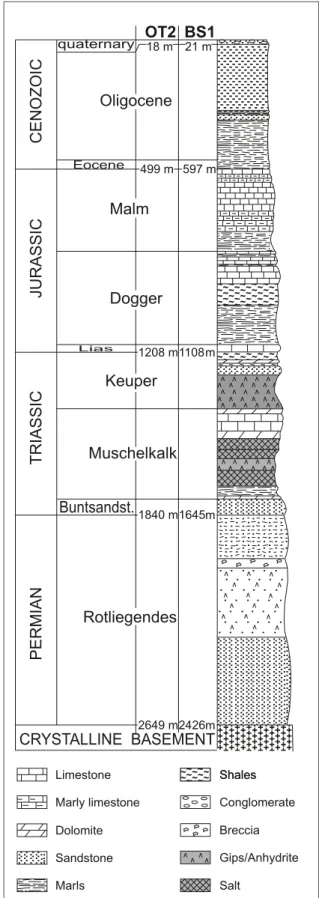
basel is located at the southern end of the Upper rhine Gra-ben, where it meets the fold and thrust belt formed by the Jura mountains (see Fig. 1). In the vicinity of the wells, the basement surface is weathered (Häring 2001) and is overlain by about 2.5 km of sedimentary cover consisting of ~800 m of sandstones (rotliegendes and buntsandstein) which give way to lime-stones and marls that extend to close to the surface (Fig. 2). the latter contain a band of evaporite units that lie between 1.3 and 1.6 km depth. the lowermost is a 100–200 m thick halite
Fig. 1. structural setting of the basel boreholes. Note that the triass beds are largely composed of evaporates layers. compiled and modified after Illies (1972), Illies & Greiner (1979), Dezayes (1996), sommaruga (1999) and Ustaszewski (2004). + + + + + + + + + ++++++++++++++++++ ++++++++++++++++++ ++++++++++++++++++ ++++++++++++++++++ ++++++++++++++++++ ++++++++++++++++++ ++++++++++++++++++ ++++++++++++++++++ ++++++++++++++++++ ++++++++++++++++++ ++++++++++++++++++ ++++++++++++++++++ ++++++++++++++++++ ++++++++++++++++++ ++++++++++++++++++ ++++++++++++++++++ ++++++++++++++++++ + + + + + + + + + + + + + + + ++++++++++++++++++++++++++++++ ++++++++++++++++++++++++++++++ ++++++++++++++++++++++++++++++ ++++++++++++++++++++++++++++++ ++++++++++++++++++++++++++++++ ++++++++++++++++++++++++++++++ ++++++++++++++++++++++++++++++ ++++++++++++++++++++++++++++++ ++++++++++++++++++++++++++++++ ++++++++++++++++++++++++++++++ ++++++++++++++++++++++++++++++ ++++++++++++++++++++++++++++++ ++++++++++++++++++++++++++++++ ++++++++++++++++++++++++++++++++++++++++++++++++++++++++++++ ++++++++++++++++++++++++++++++ ++++++++++++++++++++++++++++++ ++++++++++++++++++++++++++++++ ++++++++++++++++++++++++++++++ ++++++++++++++++++++++++++++++ ++++++++++++++++++++++++++++++ ++++++++++++++++++++++++++++++ 1000 m 750m 500m 250m 400 m Zürich Basel Mulhouse Colmar Freiburg Molas se Ba sin Jura mou ntains Upp erR hine Gra ben Bla ckFo rest Vosg es Aare Rhine Doubs Birse 0 40 km 8° 48° 7° 8° 7° 48° + + ++ + Cenozoic Detached Mesozoic Autochthonous Mesozoic Basement Anticline Fault Major normal fault Thrust or reverse fault river country border 250m Isopach of Triassic layers (without Buntst.) BS1 OT2
Fig. 2. Lithological section at Ot2 and bs1 boreholes. All depths in this paper are given along hole from ground level. the wellhead of bs-1 is 250.2 m amsl, and that for Ot-2 is 252.61 m amsl.
~~~~~~~~~~~ ~~~~~~~~~~~ ~~~~~~~~~~~ ~~~~~~~~~~~ ~~~~~~~~~~~ ~~~~~~~~~~~ - --- -+++++++++++++ +++++++++++++ +++++++++++++ +++++++++++++ ++++++++++++++ + + + + +
TRIASSIC
PERMIAN
JURASSIC
CENOZOI
C
CRYSTALLINE BASEMENT
quaternaryOligocene
EoceneMalm
Dogger
LiasOT2 BS1
18 m 21 m 499 m 597 m 1208 m1108m 1840 m1645m 2649 m2426mKeuper
Muschelkalk
Buntsandst.
Rotliegendes
Limestone Sandstone Marls Marly limestone Dolomite Shales Shales ~~~~~~ ~~~~~~~ ~ ~ ~~~~~~ ~~~~~~~ ~ ~ Conglomerate Breccia Salt Gips/Anhydritebed (salzlager), and the uppermost is an anhydrite unit (Gips-keuper) of about 150 m thickness. the evaporite beds are ex-tensive (e.g. Jordan 1994; sommaruga 1999; becker 2000) and constitute horizons of possible stress detachment (becker et al. 1987; Evans and roth 1998).
Log data and analysis methods Log data
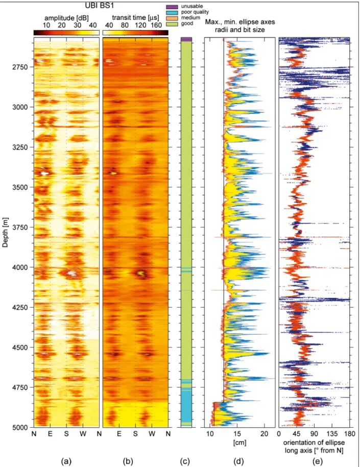
the log suite run in bs1 included a schlumberger ultrasonic televiewer (UbI) which was run between 2569 and 4992 m shortly after drilling. the log is entirely in granite and begins 25 m inside the 10–3/4 inch casing. the open hole diameter be-low the 10–3/4 inch casing shoe is 9–7/8" to 4841 m depth and 8–1/2" below. the tool was operated at a frequency of 2.5 MHz and used a focused beam that would produce a spot size of about 0.64 cm in an 8–1/2" diameter borehole containing fresh water. the transponder rotated at 6 revolutions per second, and made 180 measurements per revolution, giving an angular resolution of 2° or 0.38 cm in an 8–1/2" hole. the log was ac-quired at a logging speed of 4 m/min giving a vertical resolution is 1.016 cm. since the spot size is 0.635 cm, a small gap between measurements swathes is present.
the ultrasonic reflectivity and travel time logs acquired in the bs1 borehole are shown in Figs. 3a–b. An index of image quality based on usable image width as defined in table 1 is shown in Fig. 3c. Approximately 89% of the log is considered to be of good quality. No strong key-seats were identified (e.g. Lofts & bourke 1999). the images from the lowermost 250 m of borehole were ranked as poor quality, due to stick-slip move-ment of the sonde. this occurred every 0.5–1.0 m and involved sudden tool movements of 10–30 cm. Although this severely impacted the ability to recognise structures, it had substantially less effect on the breakout analysis. the only section of image that was totally unusable for this study is the uppermost 22 m of log where image orientation is affected by the casing.
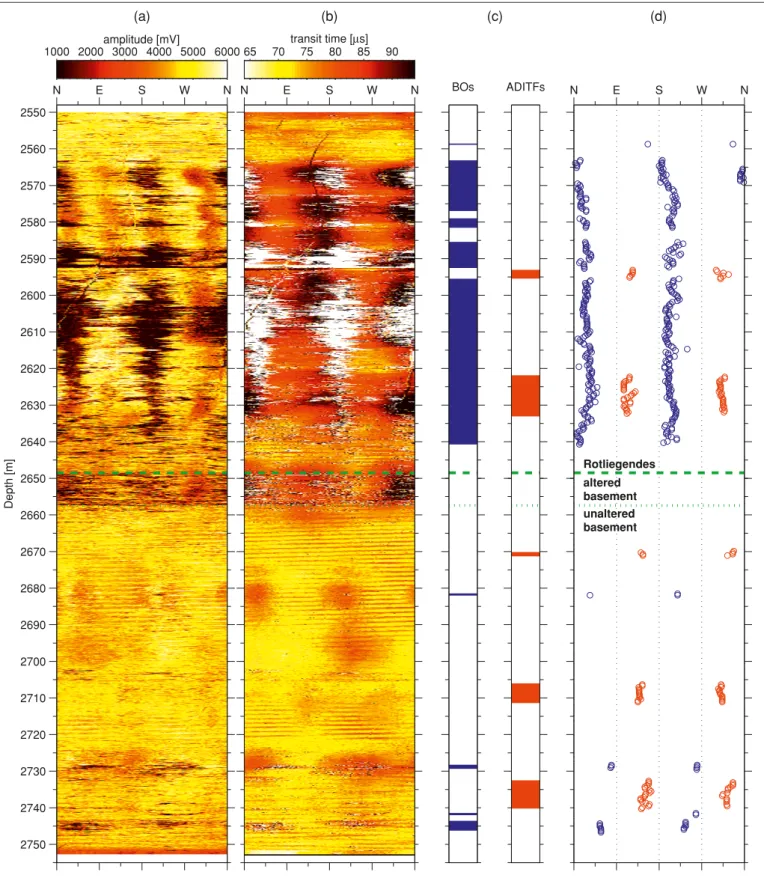
the logs in Ot2 were run by baker-Atlas and included borehole wall microresistivity (stAr) and ultrasonic tele-viewer (cbIL). Only acoustic teletele-viewer data were analysed. the televiewer was operated at a frequency of 250 KHz and had 250 samples per revolution. the logs were run from about 2550 to 2753 m depth and thus cover the lowermost 100 m of the rotliegendes sandstone and the uppermost 100 m of base-ment (Fig. 4). borehole diameter in this section is 6–1/4". the data were acquired in two runs which overlap between 2599 m and 2631 m. the lower section was logged first, and suffered problems with stick-slip movement of the sonde in the overlap interval. this occurs when the friction between the tool string and borehole wall is sufficient to bring the tool to a halt, and is promoted by wall irregularity, stiff centralisation, and depths sufficient to render the wireline system elastically compliant (Lofts & bourke 1999). the problems were much reduced in the second log of this interval, which extended to the top of the logged section. together, the two runs give a continuous log
of acceptable quality that extends through the basement-sedi-ment interface (Fig. 4a–b). A more serious limitation of these data concerns the travel-time images which frequently show di-ametrically-opposite pairs of sectors where the travel time has a constant, unrealistically-small value that would imply a bore-hole diameter smaller than the bit size. these anomalous data show as white on the image of Fig. 4b, and occur predominantly between 2565 and 2635 m depth. they often occur in zones where the travel-time suggests spalling has occurred (i.e. the dark zones of Fig. 4b). Moreover, the anomalously low travel-times are invariably accompanied by a low signal amplitude (dark zones of Fig. 4a). these observations collectively suggest an instrumental origin for the anomalous data points, triggered by the absence of a detected reflection from the borehole wall within the listening window, such as can occur through non-nor-mal incidence on an irregular borehole wall (e.g. Georgi 1985). Possible origins for the stable, anomalously-low travel times are that it was the ‘time-out’ setting chosen by the logging engineer, or that it represents the arrival time of the ‘boot reflection’. Henceforth we will assume that the anomalously-low travel times indicate spalling, an assumption that is supported both by the diametric symmetry of the zones expected for stress-induced breakouts, and their orthogonality to drilling-stress-induced tension fractures. However, it is clear that the detailed geom-etry of the spall cannot be determined from the data.
Analysis methods
two types of borehole failure are recognised as reliable stress indicators: drilling-induced tension fractures (DItFs) and breakouts. DItFs (e.g. brudy & Zoback 1999) form where the tensile tangent stress component developed by the cooling of the borehole wall by the circulating drilling mud is sufficient to produce tensile failure at some point around the borehole. the net tangent stress around the borehole is the sum of the cooling component, which is axially-symmetric, and the natu-ral wellbore stress concentration arising from the ‘far-field’ stresses, which is usually not axially-symmetric and may be ev-erywhere compressive. In the case of a vertical borehole pen-etrating a medium in which one principal stress is also verti-cal, the least compressive value of the tangent stress variation about the borehole due to the far field stresses occurs in the direction of sHmax. thus, it is in this direction that the great-est tension develops and a pair of diametrically-opposite, axial, drilling-induced tension fractures (A-DItFs) form. However,
table 1. Ultrasonic borehole image quality classification. designation usable image width examples
unusable 0% in casing, log extremities Poor quality 0–30% Large caves, stick/slip, bit
whirling medium 30–70% strong key-seat
Fig. 3. summary of UbI log from bs1: a) acoustic reflectivity log. b) transit time log. c) image quality rating. d) bit size (black line), maximum and minimum ellipse radii. e) Orientation of ellipse long axis.
Fig. 4. summary of the ultrasonic imaging (cbIL tool from baker Atlas) and borehole failure in Ot2 borehole. a) acoustic reflectivity log. b) transit time log c) breakouts (bOs) and axial drilling-induced fracture (A-DItFs) determination. d) orientation measurement of the breakouts (blue) and the axial drill-ing-induced tension fractures (red). the depth of the transition from the sedimentary cover (rotliegendes) to altered basement and unaltered basement are indicated by dashed green lines.
Depth [m ] amplitude [mV] N E S W N 2550 2560 2570 2580 2590 2600 2610 2620 2630 2640 2650 2660 2670 2680 2690 2700 2710 2720 2730 2740 2750 1000 2000 3000 4000 5000 6000 transit time [Ms] N E S W N 65 70 75 80 85 90 BOs ADITFs Rotliegendes altered basement unaltered basement N E S W N (a) (b) (c) (d)
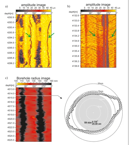
in the case where the borehole axis is not aligned with a prin-cipal stress axis, the criterion for tensile failure might still be met but then DItFs will tend to form as a stack of en-echelon fractures denoted as E-DItFs (Ito et al. 2001). the relation-ship between the induced fracture geometry and the in-situ stress orientations and magnitudes in this case is not as simple as in the aligned case (brudy & Zoback 1993). Examples of A-DItFs and E-DItFs seen in the acoustic reflectivity images of the UbI log from bs1 are shown in Figs. 5a–b. the principal difficulty when interpreting borehole images for DItFs is to distinguish them from natural fractures. In the absence of core, or deep-probing, azimuthally-focussed electric logs such as the ArI (Luthi 2001), usage was made of the tendency of A-DItFs to have slightly zigzagging trace due to fracture linkage (Ito et al. 2001). E-DItFs were distinguished from stacks of parallel natural fractures by the tendency for their trace on the images to be weak or absent near the crests of each ‘sinusoid’ (Fig-ure 5b). this is in contrast to natural fract(Fig-ures where the crests tend to be the most strongly defined part of the trace.
the orientation of each limb of each A-DItFs with respect to the borehole centre was measured every 40 cm. thus, long, continuous A-DItFs have greater weight in averaging the measurements over the entire borehole length than short A-DItFs. For example, the orientation of a 4.8 meter long pair of diametrically-opposite A-DItFs will be described by 24 mea-surements, whereas a 2.4 m single-limbed A-DItFs will gen-erate only 6 orientation measurements. the orientation of the E-DItFs was measured by fitting a sinusoid through the pair of limbs and determining the strike. Mean orientation is com-puted with each E-DItFs having the same weight.
breakouts are typically manifest as pairs of diametrically-opposite spall zones that extend along the borehole axis. they occur when the local value of tangent compression at the bore-hole wall exceeds the compressive strength of the rock. In the simple case of a vertical borehole penetrating a rock mass in which one principal stress is vertical, breakouts, if they occur, develop where the tangent stress is a maximum, which occurs in the direction of the minimum horizontal principal stress,
Fig. 5. a) Example of A-DItFs on bs1 images (green arrows). b) Example of E-DItFs on bs1 images (green arrows). c) Example of breakouts on the bs1 image (left) and the borehole cross-section computed from transit time (right).
90° 180° 270° 0° 0° depth[m] 4513.0 4514.0 4515.0 4516.0 4518.0 4519.0 4520.0 4521.0 4522.0 4523.0 4524.0 4517.0 4525.0
Borehole radius image
Bit size 9 7/8’’25.08 cm 15cm 20cm 5cm 10cm a) 4292.6 depth[m] 4293.0 4293.4 4293.8 4294.2 4294.6 4295.0 4295.4 4295.8 4296.2 amplitude image 90° 180° 270° 0° 0° depth[m] 4132.6 4133.0 4133.4 4133.8 4134.2 4134.6 4135.0 4135.4 4135.8 4136.2 amplitude image 90° 180° 270° 0° 0° 4136.6 c) b) 100 110 120 130 140 150 160 mm 5 10 15 20 25 30 35 40 45 sµ 5 10 15 20 25 30 35 40 45 sµ
shmin. breakouts affect the shape of the borehole cross-sec-tion significantly, as can be seen in Fig. 5c taken from the travel time image of bs1. stress-induced breakouts are denoted by the darker bands (i.e. larger transit time) on the transit-time log of Fig. 5c. the identification of breakouts was performed using a quality ranking as follows: ‘High-confidence’ recog-nitions had two approximately-symmetric spall zones, and a difference between the minimum and maximum borehole radius greater than 2.5 cm; ‘moderately-confidence’ break-outs differed in that the difference between the minimum and maximum borehole radius was less than 2.5 cm; and ‘low-confi-dence’ were characterised by an asymmetric cross-section with one relatively deep narrow furrow and one poorly-developed enlargement diametrically-opposite. Isolated occurrences of the latter could be key-seats. However, in the case of bs1, such sections were usually continuous with ‘high-confidence’ break-outs, suggesting that most reflected stress-induced spalling. Other types of borehole enlargement, as for example washouts (Plumb & Hickman 1985) which are characterised by a bore-hole diameter increase in all directions, were excluded from the stress induced failure database. the breakout analysis was similar to the A-DItF analysis: the orientation of each limb of each breakout was determined every 40 cm, each measure-ment representing the orientation of the centre of the spall zone with respect to the borehole centre. Mean orientations were computed using the same procedure employed for A-DItFs. In addition to this visual identification of breakouts, an automatic examination of borehole cross-section shape was performed which involved the fitting of an ellipse to the borehole cross-section every 1 cm. the procedure used a direct least square fit as describe in Halíř & Flusser (1998) to obtain the magnitude and direction of the minor and major axis. Note that such an approach is not able to distinguish between stress induced failure and borehole elongation due to other mecha-nisms, such as key-seats and washouts.
Results BS1 borehole breakouts
the results of the automatic borehole cross-section shape analysis are presented first. the profiles of minor and major axis lengths of the fitted ellipses are shown in Fig. 3d and the corresponding orientation of the major axis in Fig. 3e. sections with differences between major and minor axes greater than 2 cm, shown in red on Fig. 3e, are common. In such sections, the orientation of the major ellipse axis is very stable and has a mean orientation and standard deviation of 51° ± 13° mea-sured clockwise from true north.
For the ‘manual’ analysis, about 6,500 borehole cross-sec-tions were analysed and 9,319 orientation measurements made. some 1954 m or 81% of the logged section contained features considered to be potential stress-induced breakouts. In all,
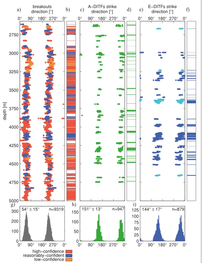
‘high-confidence’ breakouts occurred along 1369 m of bore-hole, ‘reasonably-confident’ breakouts along 457 m and ‘low-confidence’ breakouts along 128 m. the results of the analysis are presented in Figs. 6a–b. the breakouts show a consistent preferred orientation along the entire borehole section which, for all three classes taken together, is 54 ± 15° (Fig. 6 g). the ‘high-confidence’ breakouts have a preferred orientation of 52 ± 14°, and the ‘moderately-confident’ breakouts present a statistically identical orientation of 54 ± 14°. However, the ‘low-confidence’ breakout population show a significantly different mean breakout orientation of 71 ± 14°, suggesting that some reflect mechanisms unrelated to stress-induced spalling. Drilling-induced tension fractures
the A-DItFs and E-DItFs were analysed separately. In all, 245 m (10%) of the logged section in bs1 was affected by A-DItFs. the results are presented on Figs. 6c–d. the mean strike direction of A-DItFs is 151 ± 13° (Fig. 6 h).
E-DItFs are observed along 314 m of borehole (13%). the en-echelon features, like the A-DItFs, are almost certainly ten-sion fractures that are promoted by cooling during the drilling process. However, the geometry of the individual fractures and their spatial relationship to each other suggested mechanisms of their formation that are not adequately understood. conse-quently, these were considered to be less reliable indicators of stress orientation than A-DItFs and were excluded from the computation of the statistics of our stress orientation estimates. they have a mean strike direction of 144 ± 17°, with 82% dip-ping to the sW (see Figs. 6e–f). their strike direction is thus consistent with the strike direction of A-DItFs, supporting the view that they are stress induced.
OT2 borehole breakouts
the presumed failure of the cbIL tool to register a reflection from azimuthal sectors of the hole that had suffered spalling means that the geometry of the spall is unknown. thus, for these data we were unable to perform an automatic analysis by fitting ellipses, nor rank the certainty of the breakout identification. the azimuthal extent of the breakouts was taken as defined by the sectors of borehole enlargement indicated by either longer travel-times or anomalously-short travel times and low ampli-tudes, as discussed earlier (see Figs. 4 a–b). the orientation of the breakouts was determined in the same way as for the bs1 breakouts (Figs. 4 c–d). breakouts occurred for 74 m or 37% of the analysed borehole length, mostly in the sedimentary section where 69 m or 70% was affected. In contrast, only 5 m or 5% of the basement section suffered breakouts. the mean orientation of breakouts is shown in the histograms of Fig. 7 and is 23 ± 11° in the sedimentary section and 62 ± 14° in the basement. Note that the relatively small number of measurement compared to bs1 produce relatively small standard deviations.
Fig. 6. summary of stress induced wellbore failure in bs1. From left to right: a) breakouts orientation determinations. b) breakouts intervals with rating of confidence level. c) A-DItFs orientation measurements. d) A-DItF intervals. e) E-DItF measurements. Dark blue denotes features dipping to the sW and light blue features dipping to the NE. f) E-DItF intervals. g) Histogram of breakouts orientation. h) Histogram of A-DItFs orientation. i) Histogram of E-DItFs strike direction. 0° 90° 180° 270° 0° 2750 3000 3250 3500 3750 4000 4250 4500 4750 5000 breakouts direction [°] depth [m ] 0° 90° 180° 270° 0° A−DITFs strike direction [°] 0° 90° 180° 270° 0° E−DITFs strike direction [°] 0° 90° 180° 270° 0° 0 100 200 300 54° p 15° n=9319 0° 90° 180° 270° 0° 0 50 100 150 151°p 13° n=947 0° 90° 180° 270° 0° 0 25 50 75 100 125 144° p 17° n=879
a)
b)
c)
d)
e)
f)
g)
h)
i)
high−confidence reasonably−confident low−confidenceDrilling-induced tension fractures
A-DItFs were found in both the sediment and basement sec-tions (Fig. 4c–d). A-DItFs occur in two clusters in the lower-most ~100 m of sediments where they have a cumulative length of 14 m and an orientation of 123 ± 11° (Fig. 7c). In the 100 m of basement, A-DItFs were again clustered, with cumulative length of 14 m, and have an orientation of 144 ± 10° (Fig. 7d).
Discussion
the boreholes are sufficiently close to vertical to permit the orientation of breakouts and DItFs to be taken as direct
in-dicators of the orientation of the principal horizontal stresses. the deviation from verticality of bs1 is less than 4° above 3600, less than 6° above 4600 m and never exceeds 8°, the azimuth varying between 270° and 360°. the Ot2 deviation from ver-tical is 7° towards N300° E for the depth of interest. the ori-entations of sHmax derived from the analyses of breakouts and A-DItFs for both holes are listed in table 2 and shown in Fig. 8. ‘Low-confidence’ breakouts and E-DItFs were not in-cluded for the reasons mentioned earlier. the breakouts in bs1 indicate a mean sHmax orientation in the granite of 143 ± 14° and the A-DItFs indicate 151 ± 13°. combining both types of indicator gives a mean orientation for sHmax of 144 ± 14°. We consider this to be the definitive result for mean sHmax
orien-Fig. 7. stress orientation indicators for the Ot-2 borehole: a) breakouts in the sedimentary sec-tion. b) breakouts in the granite secsec-tion. c) A-DItFs in the sedimentary section. d) A-A-DItFs in the granite section.
0 90 180 270 360 0 20 40 60 80 BOs sedimentary orientation n n = 351 23°p 11° 0 90 180 270 360 0 5 10 15 20 25 ADITFs sedimentary orientation n n = 64 123°p 11° 0 90 180 270 360 0 2 4 6 8 BOs basement orientation n n = 25 62°p 14° 0 90 180 270 360 0 5 10 15 ADITFs basement orientation n n = 67 144°p 10° a) b) c) d)
table 2. summary of stress orientation determination.
Borehole Coordinates Collar altitude Lithology/Failure type Number of distinct zones Combined failure length (% of failed borehole) SHmax orient. Quality ranking after WSW scheme Ot2 swiss grid: 612 424 / 269 684 WGs84: 7° 36' 13.55" E 47° 34' 39.86" N 253 m a. s. l. sediment A-DItFs 2 14 m (14%) 123 ± 11° E breakouts 5 69 m (70%) 113 ± 11° c basement A-DItFs 3 14 m (14%) 144 ± 10° E breakouts 4 5 m (5%) 152 ± 14° D bs1 swiss grid: 611'808 / 270'531 WGs84: 7° 35' 44.16" E 47° 35' 07.32" N 250 m a. s. l. basement A-DItFs 38 245 m (10%) 151 ± 13° b breakouts 182 1954 m (81%) 143 ± 14° b
tation in the granite from 2600 m to 5000 m, and note it is con-sistent with the estimate for the uppermost 100 m of the granite obtained from the less-numerous breakouts and A-DItFs in Ot2 of 152 ± 14° and 144 ± 10°, respectively. the orientation of sHmax is very stable within the basement when averaged over scales of several hundred meters, although more-or-less
continuous variations are seen at shorter scales. these prob-ably reflect stress heterogeneity related to stress perturbations at fractures, the analysis of which is beyond the scope of this paper.
the primary purpose of including the results from Ot2 in the analysis was to examine sHmax orientation near the
sedi-Fig. 8. summary of the orientation of reliable stress indicators. a) High-confidence breakouts in bs1. b) A-DItFs in bs1. c) breakouts in the basement section of Ot2 d) A-DItFs in the basement section of Ot2. e) breakouts in the sedimentary section of Ot2 f) A-DItFs in the sedimentary section of Ot2. g) sHmax orientation (mean orientation and single circular standard deviation) derived from these indicators.
2% 4% 6% mean direction : 53°p 14° N=8750 2% 4% 6% mean direction : 151°p 13° N=947 BS1 breakouts 143°p 14° BS1 A−DITFs 151°p 13°
OT2 A−DITFs sediment 123°p 11°
OT2 A−DITFs basement 144°p 10°
OT2 breakouts sediment 113°p 11°
OT2 breakouts basement 152°p 14° 5% 10% 15% 20% mean direction : 123°p 11° N=64 5% 10% 15% mean direction : 144°p 10° N=67 5% 10% 15% mean direction : 23°p 11° N=351 5% 10% 15% 20% mean direction : 62°p 14° N=25
a) High−confidence breakouts in BS1 b) A−DITFs in BS1
g) SHmax orientation summary
f) A−DITFs in OT2 sedimentary section d) A−DITFs in OT2 basement section
e) breakouts in OT2 sedimentary section c) breakouts in OT2 basement section
ment interface. In the lowermost 100 m of the sedimentary sec-tion, A-DItFs have a cumulative length of 14 m and indicate a mean sHmax orientation of 123 ± 11°, whereas breakouts ex-tend over 69 m and suggest an sHmax orientation of 113 ± 11°. comparison with the results from DItFs and breakouts in the granite of N144° and 152° respectively suggest an ~30° change in sHmax orientation occurs near the basement interface. Whilst the number of data in the sedimentary section is relatively limited compared to the large number of data collected in the basement in the borehole bs1, which probably explains the 17° asymmetry of the mean orientation of the two DItF lobes in Fig. 8f, the orientation change is larger than can reasonably be attributed to noise. It should be noted that both breakouts and DItFs in the lowermost part of the sedimentary section were imaged in the same logging run used for the basement section, and thus the discrepancy in orientations cannot be attributed to changes in the sonde configuration. In view of this, it is con-cluded that a small but significant change in sHmax orientation occurs at the basement-sediment interface.
the origin of the change in stress at the basement-sediment interface is unclear. there is no evidence of a fracture zone or fault cutting the well near the interface. since the latter consti-tutes an unconformity between the rotliegende sediment and the weathered upper part of the granite, a contrast in mechani-cal properties between the sediment and intact granite can be expected which extends across the weathered zone. stiffness contrast between beds subject to strain can produce bed-to-bed changes in stress magnitude and direction as shown by the field observations and modelling results of bruno and Winter-stein (1994) and Gudmundsson (2006, 2009). However, if the deformation is uniform horizontal straining, then the develop-ment of changes in horizontal stress orientation between beds of different elastic stiffness requires some obliquity of the beds to the horizontal plane (bruno and Winterstein, 1994), or the presence of elastic anisotropy in the horizontal plane. Although we cannot rule these out, the available information provides no indication of strong horizontal elastic anisotropy of the bulk rock elastic properties, and the topography of the granite sur-face is believed to be mild with a large-scale dip of ~12° to the east, which largely accounts for the different depths to the granite in the two wells (the wellhead heights above sea level differ by only 2 m – see Fig. 2). Another possible explanation is that the change in stress orientation reflects the presence of remnant stresses. Immediately prior to the deposition of the rotliegende, some stress state appropriate for an erosional sur-face existed in the crystalline basement, and it is more probable than not that the stresses were anisotropic in the horizontal plane. this stress state would not be present in the sedimentary rocks that were subsequently deposited, and hence a contrast in horizontal stress would be present. However, since the granite was at the surface at the onset of deposition, the stress magni-tudes near the interface would be relatively small in compari-son to subsequent modification from burial and loading, and it is questionable whether they could explain 20–30° of rotation of sHmax at the interface today. thus, the origin of the stress
orientation change in the Ot2 stress profile at the interface is uncertain. It is important to note that the present data do not define whether it is a local or extensive feature. Nevertheless, the practical consequence of a 20–30° error in stress orientation for the design and development of an EGs in the basement would be significant, and serve to emphasise the importance of obtaining stress information within the target reservoir and not extrapolating from shallower measurements.
the quality ranking of the different stress estimates fol-lowing the ranking scheme of the World stress Map project (sperner et al. 2003) is given in table 2. Under this scheme, the results from Ot2 would be ranked as questionable (D) or not reliable (E) except for the breakouts in the sedimentary sec-tion which would be ranked as ‘c’ (i.e. standard deviasec-tion in the range 20–25°). the stress orientation estimates from the A-DItFs and breakouts in bs1 would both be ranked as ‘b’ quality, despite stemming from almost 2 km of data. We believe the failure to rank the bs1 data as ‘A’ reflects limitations in the WsM quality ranking scheme in deep boreholes with perva-sive borehole failure, rather than deficiencies in the data. Un-der the WsM scheme, a ‘b’ quality is mandated because the standard deviation is 14° rather than ≤12° as required for ‘A’ quality estimates. However, the standard deviation reflects true stress heterogeneities in the basement that only long profiles can capture. We note that other long profiles of sHmax orienta-tion from wellbore failure at soultz (Valley & Evans 2010) and the Ktb (brudy & Zoback 1999) also rank as ‘b’ for the same reasons. such information is valuable and should not lead to degradation in the quality of the indicator.
the relation of the mean sHmax orientation from borehole bs1 to other basement stress indicators in the region about ba-sel is shown in Fig. 9d and e. Most estimates are from break-outs, with some hydrofracture and overcoring measurements. the areas labelled F3 and F4 denote regions of uniform stress defined from rigorous inversion of fault plane solutions (FPs) of earthquakes that lie within the boundaries drawn on the fig-ure (Kastrup et al. 2000). Most events lie at depths of 10–15 km, with some extending to 20 km depth for area F3 of the alpine foreland. the mean orientation of shmin for both regions was found to be N55° E. Deichmann and Ernst (2009, this volume) derived fault plane solutions for the 28 strongest events induced within the rock mass around bs1 by the stimulation injections of 2007. they found the orientation of the t-axis of the events was sub-horizontal and oriented N48°E ± 13°. thus, with the exception of the overcoring measurements, all basement data indicate NW–sE oriented compression. the agreement of the mean shmin orientation from bs1 with that indicated by in-version of the FPss from the areas F3 and F4 to the south and north, and the t-axes of events within the rock volume around the well provides support for the validity of the relatively in-direct stress-orientation estimates obtained from the FPss of both natural and induced seismic events respectively.
the NW-orientation of sHmax is consistent with the aver-age sHmax-orientation of the large-scale stress field of West-ern Europe north of the swiss alpine foreland that is believed
to be related to the push from the North Atlantic ridge and to the convergence between Africa and Europe (Müller et al. 1992). We see no evidence of a rotation of sHmax towards a more NNW- to N-orientation below 3 km, as tentatively pro-posed by cornet et al. (2007) to be a characteristic of stress in north-western Europe.
the oriented logs run in bs1 and Ot2 do not extend higher than 80 m above the basement interface, and so the data do not allow the question of whether a further change in stress
orientation occurs at the evaporites, as reported for measure-ments conducted elsewhere in the swiss foreland basin (Mül-ler et al. 1987). Extensive salt detachments often constitute stress discontinuity horizons (Davis & Engelder 1985): for example, Evans (1989) found a discontinuity in horizontal stress magnitude across the salinian salt of the Appalachian basin, and röckel and Lempp (2003) report a discontinuity in horizontal stress magnitude and direction at the Zechstein salt in the North German basin. It is thus of interest to compare
Fig. 9. Estimates of sHmax orientation for the Upper rhine Graben and swiss foreland region centred on basel. a) Lithological section (see also Figure 2) show-ing the data catchment zones. the stress data presented here are either above the evaporate layers (decollement level), in the sediments below the evaporate layers or in the crystalline basement. b) and c) Estimates of sHmax orientation in the Mesozoic and younger section that lies within or above the evaporite layers (after Evans & roth 1998). d) and e) Estimates of sHmax orientation in the crystalline basement derived from various borehole measurements and the inver-sion of focal mechanisms of earthquakes (the areas of uniform stress defined by the earthquake populations used in the inverinver-sions are outlined). the key to the datapoint numbers are as follows: 1/2/3/4 (becker et al. 1987; blümling 1986); 5/6 (Wolter 1987); 7 (becker and Paladini, 1992; rummel & baumgaerner 1987); 8 (baumgärtner & Zoback 1989); 9 reinecker et al. (2005); 20 (Gysel 1975); 21/22/23 (becker et al. 1987; blümling 1986); 24/25 (Müller et al. 1987); 26/27/28/30 (becker et al. 1987); 31 (becker & Werner 1995); 32/33 (Greiner & Illies 1977); 34/35 (cornet & burlet 1992); 36 (Leopoldt 1979).
Basel Freiburg Zürich Mulhouse Colmar 1 2 3 4 5,6 7 8 F4 F3 7°E 8°E 48°N 47°N BS1 & OT2 basement OT2 sediments Basel Freiburg Zürich Mulhouse Colmar 20 21 22 23 24 25 26 27 28 29 30 31 32 33 34 35 36 7°E 8°E 48°N 47°N
Stress relief method Hydrofracture type method Geological indicator
Borehole breakouts method Focal mechanism inversion 0 m 500 1000 1500 2000 2500 3000 3500 4000 4500 5000 TRIASSIC PERMIAN JURASSIC CENOZOIC CR YS TA LLINE BASEMENT Evaporite layer potential decollement level Data on map b) and rosette c) Data on map d) and rosette e) BS1 data OT2 data a) b) d) e) c) N E S W 5% 10% 15% 20% n=17 OT2 sediments BS1 & OT2 basement 15% 30% 45% n=11 60% N E S W 0 40 km 0 40 km
the sHmax-orientation results from the two boreholes with those from near-surface stress measurements conducted above the evaporite horizon in the vicinity of basel. these data are shown in Fig. 9b. Most derive from overcoring or borehole slot-ter measurements conducted at shallow depth in quarries or tunnels, although they also include hydrofracture orientation data from relatively large-volume injections into Muschelkalk beds at depths of 550–850 m at a potash mine, and an active salt diapir (cornet & burlet 1992: data points 34 and 35 resp. in Fig. 9b). the scatter in the collective data is much greater than seen in the generally deeper crystalline measurements, reflect-ing the highly-heterogeneous nature of the near-surface state of stress. If the heterogeneity reflects random fluctuations in an otherwise uniform stress field, then averaging can be applied to resolve the underlying uniform trend. the average sHmax orientation of the 7 data points taken within 50 km of basel is N177°E ± 66° (note this is not strictly the best standard devia-tion estimate since the error associated with each individual data point was not included). the mean value of N177° E dif-fers markedly from the basement orientation of N144°E ± 14°, although whether this reflects a systematic difference in mean sHmax orientation above or below the evaporites is not strictly resolved: for even if the conditions required to render averag-ing sensible are satisfied, the standard deviation is so large as to require more data points in order to robustly distinguish be-tween N–s and NW–sE orientations of sHmax. Nevertheless, the shallower data do favour a more N–s orientation, and the deeper hydrofracture data and an active salt diapir (cornet & burlet, 1992): data point 35 in Fig. 9b) support the assertion that the stress field above the evaporites in the rhine Graben within 50 km of basel is on average oriented N–s, and that a change in sHmax-orientation occurs at the evaporite horizon. thus, in the section studied, there is at least one and possibly two horizons where a discontinuity in sHmax-orientation oc-curs. For deep geothermal energy development, this result em-phasises the need to determine the stress state in the target res-ervoir rock rather than relying on extrapolation of data from shallower horizons.
Conclusions
Analysis of the orientation of breakouts and drilling-induced tension fractures in two deep boreholes penetrating the crys-talline basement under the city of basel indicates a mean ori-entation of sHmax within the granite from near the sediment interface down to 5 km depth is N144° E ± 14°. the orienta-tion of sHmax is very stable within the basement when aver-aged over scales of several hundred meters, and is consistent with the results of analyses of the focal mechanism solutions of natural regional earthquakes and also events induced during the injections. DItFs and breakouts in the rotliegend sand-stone that lies immediately above the basement indicate an sHmax orientation of N115°E ± 12°, suggesting a ~30° change in sHmax-orientation occurs near the basement-sediment in-terface. the origin of this change is uncertain. the logs do not
extend higher than 80 m above the interface, and so the profile of sHmax orientation does not extend through the evaporites. Near-surface measurements within 50 km of basel suggest a mean orientation of N–s, although the variability is very large. Nevertheless, an average N–s orientation for sHmax above the evaporites within 50 km of basel is also suggested by hy-drofractures induced at up to 850 m depth and a salt diapir. thus, the balance of evidence suggests an sHmax orientation change also occurs at the evaporite horizon. changes in stress orientation can have significant practical consequences on the design and development of an EGs, and serve to emphasise the importance of obtaining estimates within the target rock mass.
Acknowledgments
We are grateful to GeoPower basel for permission to publish these data. Keith Evans acknowledges the support of Project GEOtHErM that is funded by the EtH competence centre for Environment and sustainability. We thank Eva schill and Agust Gudmundsson for helpful reviews.
rEFErENcEs
baumgärtner, J. & Zoback, M.D. 1989: Interpretation of hydraulic pressure-time records using interactive analysis methods. International Journal of rock Mechanics, Mining science & Geomechanics Abstract 26, 461–471. becker, A. 2000: the Jura Mountains – an active foreland fold-and-thrust belt?
tectonophysics 321, 381–406.
becker, A., blümling, P. & Müller, W.H. 1987: recent stress field and neotec-tonics in the Eastern Jura Mountains, switzerland. tectonophysics 135, 277–288.
becker, A. & Paladini, s. 1992: Intra-plate stresses in Europe and plate driving mechanisms. Annales tectonicae 6, 173–192.
becker, A. & Werner, D. 1995: Neotectonic state of stress in the Jura moun-tains. Geodinamica Acta 8, 99–111.
blümling, P. 1986: In-situ spannungsmessungen mit Hilfe von bohrlochrand-ausbrüchen und die spannungsverteilung in der Kruste Mitteleuropas und Australiens. Ph.D. thesis, Karlsruhe University, Germany.
brudy, M. & Zoback, M.D. 1993: compressive and tensile failure of boreholes arbitrarily inclined to principal stress axes. International Journal of rock Mechanics, Mining science & Geomechanics Abstract 30, 1035–1038. brudy, M. and Zoback, M.D. 1999: Drilling-induced tensile wall-fractures:
implications for determination of in-situ stress orientation and magni-tude. International Journal of rock Mechanics and Mining science 36, 191–215.
bruno, M.s. & Winterstein, D.F. 1994: some influences of stratigraphy and structure on reservoir stress orientation. Geophysics 59, 954–962. cornet, F.H. & burlet, D. 1992: stress field determination in France by
hydrau-lic tests in boreholes. Journal of Geophysical research 97, 11829–11849. cornet, F., bérard, F.H. & bourouis, s. 2007: How close to failure is a granite
rock mass at a 5 km depth? International Journal of rock Mechanics and Mining science 44, 47–66
Davis, D.M. and Engelder, t. 1985: the role of salt in fold-and-thrust belts. tectonophysics 119, 67–88.
Deichmann, N, and J. Ernst 2009: Earthquake focal mechanisms of the induced seismicity in 2006 and 2007 below basel (switzerland). submitted to swiss Journal of Geosciences.
Dezayes, c. 1996: caractérisation et interprétation d’un volume rocheux frac-turé à partir de données de forages, les forages géothermiques de soultz-sous-Forêts. PhD thesis, Université de savoie, chambéry France, 200 pp. Evans, K.F. 1989: Appalachian stress study 3. regional scale stress variations
and their relation to structure and contemporary tectonics. Journal of Geophysical research 94(b12), 17619–17645.
Evans, K.F. & roth, P. 1998: the state of stress in northern switzerland in-ferred from earthquake seismological data and in-situ stress measure-ments. Proseis AG, sewardstrasse 7, cH-8050 Zürich, switzerland. Evans, K.F., Moriya, H., Niitsuma, H., Jones, r.H., Phillips, W.s., Genter, A.,
sausse, J., Jung, r. & baria, r. 2005: Microseismicity and permeability enhancement of hydrogeologic structures during massive fluid injections into granite at 3 km depth at the soultz HDr site. Geophysical Journal International 160, 388–412.
Georgi, D.t. 1985: Geometrical aspects of borehole televiewer images. In: sPWLA 26th Annual Logging symposium, society of Petrophysicists & Well Log Analysts.
Greiner, G. & Illies, J.H. 1977: central Europe: Active or residual tectonic stresses, Pageoph 115, 11–26.
Gudmundsson, A. 2006: How local stresses control magma-chamber ruptures, dyke injections, and eruptions in composite volcanoes. Earth-science re-views 79, 1–31.
Gudmundsson, A., simmenes, t.H., Larsen, b. and Philipp, s. 2009: Effects of internal structure and local stresses on fracture propagation, deflection, and arrest in fault zones. Journal of structural Geology, in Press. Gysel, M. 1975: In-situ stress measurements of the primary stress state in the
sonnenberg tunnel in Luzerne, switzerland. tectonophysics 29, 301–314. Haering, M.O. 2001: technischer bericht Geothermie-sondierbohrung Ot-terbach 2, basel. technical report. Geothermal Explorer Ldt. Pratteln, switzerland.
Haering, M.O., schanz, U., Ladner, F., and Dyer, b.c. 2008: characterisation of the basel 1 enhanced geothermal system. Geothermics 37(8), 469–495. Halíř, r. & Flusser, J. 1998: Numerically stable Direct Least squares Fitting of
Ellipses. In: skala, V. (Eds): Proceedings of the International conference in central Europe on computer Graphics, Visualization and Interactive Digital Media, 125–132.
Ito, t., Zoback, M.D. & Peska, P. 2001: Utilization of mud weights in excess of the least principal stress to stabilize wellbores: theory and practical examples. sPE Drilling and completion 16, 221–229.
Illies, H. 1972: the rhine graben rift system – plate tectonic and transform faulting. Geophysical survey 1, 27–60.
Illies, H.J. and Greiner, G. 1979: Holocene movements and state of stress in the rhine Graben rift system. tectonophysics 52(1–4), 349–359.
Jordan, P. 1994: Evaporite als Abscherhorizonte, Ein gefügekundlich-struktur-geologische Untersuchung am beispiel der Nordschweiz trias. beiträge zur Geologischen Karte der schweiz 164, 79 pp.
Kastrup, U., Zoback, M.L., Deichmann, N., Giardini, D., Evans, K.F. & Mi-chael, A.J. 2004: stress field variations in the swiss Alps and the northern Alpine foreland derived from inversion of fault plane solutions. Journal of Geophysical research 109, b01402, doi:10.1029/2003Jb002550.
Leopoldt, W. 1979: In situ spannungsmessungen am Michelsberg bei riegel, Nordöstlicher Kaiserstuhl, südwestdeutschland. Oberrheinische geolo-gische Abhandlungen 28, 17–28.
Lofts, J.c. & bourke, L.t. 1999: the recognition of artefacts from acoustic and resistivity borehole image devices. In: Lovell, M. A., Williamson, G. & Harvey, P. K. (Eds): borehole Imaging: applications and case histories. Geological society special publications, London. 59–76.
Luthi, s.M. 2001: Geological well logs: their use in reservoir modelling. springer. IsbN- 978–3540678403. 373 pp.
Müller, W.H., blümling, P., becker, A. & clauss, b. 1987: Die Entkopplung des tektonischen spannungsfeldes an der Jura-Ueberschiebung. Eclogae Geologicae Helvetiae 80, 473–489.
Müller, b., Zoback, M.L., Fuchs, K., Mastin, L., Gregersen, s., Pavoni, N., stephansson, O. & Ljunggren, c. 1992: regional patterns of tectonic stress in Europe. Journal of Geophysical research 97, 11783–11803. Phillips, W.s. 2000: Precise microearthquake locations and fluid flow in the
geothermal reservoir at soultz-sous-Forêts, France. bulletin of the seis-mological society of America 90, 212–228.
Pine, r.J. and batchelor, A.s. 1984: Downward migration of shearing in jointed rock during hydraulic injections. International Journal of rock Mechan-ics and Mining science 21, 249–263.
Plumb, r.A. and Hickman, s. 1985. stress-induced borehole elongation; a comparison between the four-arm dipmeter and the borehole televiewer in the Auburn geothermal well. Journal of Geophysical research 90(b7), 513–552.
reinecker, J., Heidbach, O., tingay, M., sperner, b., & Müller, b. 2005: the 2005 release of the World stress Map (available online at www.world-stress-map.org).
röckel, t. and Lempp, c. 2003: the state of stress in the North German basin. Erdöl, Erdgas, Kohle 119(2), 73–80.
rummel, F. & baumgärtner, J. 1987: Hydrofrac spannungsmessungen in den geothermischen Erkundungsbohrungen des Kontinentalen tiefbohrpro-gramms in schwarzwald und in der Oberpfalz. report to Deutsche For-schungs-Gemeinschaft.
sommaruga, A. 1999: Décollement tectonics in the Jura foreland fold-and-thrust belt, Marine and Petroleum Geology 16, 111–134.
sperner, b., Müller, b., Heidbach, O., Delvaux, D., reinecker, J., Fuchs, K. 2003: tectonic stress in the Earth’s crust: Advances in the World stress Map Project. In: Nieuwland D. (Eds): New insights in structural interpre-tation and modelling. Geological society of London, special Publications 212, 101–116.
Ustaszewski, K.M. 2004: reactivation of pre-existing crustal discontinuities: the southern Upper rhine Graben and the northern Jura Mountains – a natural laboratory. PhD thesis. Naturwissenschaft Fakultät der Univer-sität basel, 178 pp.
Valley, b. and Evans, K.F. 2010: stress Heterogeneity in the Granite of the soultz EGs reservoir Inferred from Analysis of Wellbore Failure. In: World Geothermal congress, bali, 25–29 April 2010, International Geo-thermal Association.
Wolter, K.E. 1987: Untersuchung der in situ spannung, residualspannung und der Mikroriss-systeme in Graniten süddeutschlands. Ph.D. thesis, Karls-ruhe University, Germany.
Manuscript received January 17, 2009 revision accepted July 8, 2009 Published Online first December 9, 2009 Editorial Handling: A. Hirt & s. bucher