Flux Synthesis, Structure, Properties, and Theoretical Magnetic Study of Uranium(IV)-Containing A 2 USi 6 O 15 (A = K, Rb) with an Intriguing Green-to-Purple, Crystal-to-Crystal Structural Transition in the K Analogue
Gregory Morrison, † Harry Ramanantoanina, ‡ Werner Urland, ‡ Mark D. Smith, † and Hans-Conrad zur Loye* ,†
†
Department of Chemistry and Biochemistry, University of South Carolina, Columbia, South Carolina 29208, United States
‡
Department of Chemistry, University of Fribourg, Chemin du Muse e 9, 1700 Fribourg, Switzerland ́
ABSTRACT: The fl ux growth of uranium(IV) oxides presents several challenges, and to the best of our knowledge, only one example has ever been reported. We succeeded in growing two new reduced uranium silicates A
2USi
6O
15(A = K, Rb) under fl ux growth conditions in sealed copper tubes. The compounds crystallize in a new structure type with space group C2/c and lattice parameters a = 24.2554(8) Å, b = 7.0916(2) Å, c = 17.0588(6) Å, β = 97.0860(6) ° (K) and a = 24.3902(8) Å, b = 7.1650(2) Å, c = 17.2715(6) Å, β = 96.8600(6) ° (Rb). A
2USi
6O
15(A = K, Rb) are isocompositional to a previously reported Cs
2USi
6O
15, and the two structures
are compared. K
2USi
6O
15undergoes an interesting crystal-to-crystal structural phase transition at T ≈ 225 K to a triclinic structure, which is accompanied by an intense color change. The magnetic properties of A
2USi
6O
15(A = K, Rb, Cs) are reported and di ff er from the magnetism observed in other U
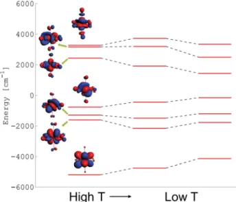
4+compounds. Calculations are performed on the (UO
6)
−8clusters of K
2USi
6O
15to study the cause of these unique magnetic properties.
■ INTRODUCTION
Uranium silicates have been studied as the abundance of silicon in the earth ’ s crust can readily lead to the formation of uranium silicates when spent nuclear fuel interacts with the environ- ment
1,2or when a reactor core experiences a meltdown.
3Furthermore, the high melting point and durability of many silicates make uranium silicates good candidates for nuclear waste storage materials. For this application, U(IV)-containing silicates are desired, due to the low solubility of U(IV) ions in water.
4,5Not surprisingly, the majority of the naturally occurring uranium silicates, formed in an oxygen-rich environ- ment, as well as most laboratory-prepared uranium silicates, contain uranium in the fully oxidized U(VI) oxidation state.
6−14Nonetheless, several examples of laboratory-prepared U(IV)- containing silicates have been reported, namely, Cs
2U
4+Si
6O
15,
13Cs
2K(U
4+/5+O)
2Si
4O
12,
15Cs
4(U
5+O)- ( U
4 + / 5 +O )
2( S i
2O
7)
2,
1 6a n d N a
7U
4 +O
2( U
5 +O )
2- (U
5+/6+O
2)
2Si
4O
16.
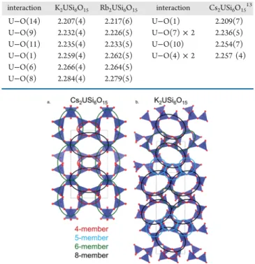
17Notably, Cs
2USi
6O
15contains [Si
2O
5] unbranched dreier single layers connected into a three- dimensional framework by UO
6octahedra.
13Almost all of the reported uranium(IV)-containing silicates have been grown under hydrothermal conditions, typically with UO
3and a reducing agent. For example, Cs
2USi
6O
15was synthesized through the reduction of UO
3by Al metal in the presence of CsF and SiO
2under hydrothermal conditions.
13An exception is (Ca
0.5Na
0.5)
2NaUSi
8O
20, which was grown using a fl ux-assisted solid-state synthesis, in which a small amount of Na
2WO
4was used to substantially reduce the temperature
required for single-crystal growth.
18Along with hydrothermal growth, the fl ux growth of reduced uranium oxides is desirable as the higher temperature regime available to fl ux growth o ff ers the potential of stabilizing new compounds that cannot be grown at lower temperatures. However, the fl ux growth of uranium(IV)-containing oxides is extremely rare. (Cu,Mn)- UMo
3O
12has been prepared via fl ux growth using UO
2(CH
3COO)
2· 2H
2O as a uranium source, a MoO
3fl ux, and Ar to provide an inert atmosphere,
19and K
8U
7O
24has been grown using a mixture of UO
2and UO
3as the uranium source and a KF fl ux in a sealed copper tube.
20The fl ux growth of several U(V) oxides has been reported from Cs
2SO
4,
21H
3BO
3,
22and ACl (A = alkali metal) fl ux.
23The single-crystal synthesis of several U(IV) fl uorides has also been reported using UF
4and a LiCl − ZnCl
2eutectic fl ux under argon in a monel alloy reactor.
24,25Furthermore, the fl ux growth of many reduced uranium chalcogenides using a variety of fl uxes including BaS, BaBr
2/KBr, and CsCl, in sealed tubes, has been reported.
26−32However, the flux synthesis of uranium(IV) oxides presents several further challenges. UO
2is inert to many solvents, including alkali chloride fl uxes
33such as the one used for the U(IV) fl uoride syntheses. Furthermore, the low oxygen concentrations required for the synthesis of reduced uranium oxides often favors the formation of nonoxide products.
34Published in ,QRUJDQLF&KHPLVWU\±
which should be cited to refer to this work.
http://doc.rero.ch
Although UO
2is only weakly soluble in chloride melts,
33it readily dissolves in the alkali fl uoride fl uxes that we have explored for the crystal growth of U(VI)-containing oxides.
20Using this approach, we succeeded in growing single crystals of two new reduced uranium silicates, A
2USi
6O
15(A = K, Rb), using the fl ux growth method. These compounds, while isocompositional to the previously reported Cs
2USi
6O
15, adopt a new monoclinic structure type. Herein, we report the fl ux growth of A
2USi
6O
15(A = K, Rb, Cs), compare the two structure types, and report the optical and magnetic properties of these three compounds along with a theoretical study of the magnetism of K
2USi
6O
15.
■ EXPERIMENTAL SECTION
Synthesis. A
2USi
6O
15(A = K, Rb, Cs) were grown using the flux growth method. KF (Alfa Aesar, powder, 99%), KCl (Mallinckrodt Chemicals, crystalline, ACS grade), RbF (Alfa Aesar, crystalline, 99.7%), RbCl (Alfa Aesar, crystalline, 99%), CsF (Strem Chemicals, powder, 99.9%), and CsCl (Alfa Aesar, crystalline, 99%) were used as received. SiO
2(Aldrich, fused pieces <4 mm, 99.99%) was ground in a ball mill for several hours and passed through a 250 μm sieve. UO
2was prepared by heating U
3O
8(International Bio-Analytical Industries, powder, ACS grade) in a tube furnace at 650 ° C for 18 h under a fl ow of 4% H
2in N
2. Caution! Although the uranium precursors used contain depleted uranium, standard safety measures for handling radioactive substance should be followed.
A
2USi
6O
15was prepared by layering a mixture of 0.5 mmol UO
2and 3 mmol SiO
2under a mixture of 9 mmol AF and 11 mmol ACl in a copper tube, which was crimped and sealed on one end with a spot- welder. The AF/ACl fl ux is on the eutectic of KF/KCl (45% KF, 606
° C) and near the eutectics for RbF/RbCl (46.4% RbF, 550 ° C) and CsF/CsCl (49.6% CsF, 439 °C). The reagents were dried in a vacuum furnace at 160 °C for 15 min before the other end of the tube was crimped and sealed. The sealed tubes were placed in tube furnaces under flow of nitrogen to prevent the copper from oxidizing and rapidly heated to 900 ° C in 1.5 h, dwelled at this temperature for 12 h, and slowly cooled to 700 ° C (K), 500 ° C (Rb), or 400 ° C (Cs) at a rate of 2 °C/h (K) or 6 °C/h (Rb, Cs), at which temperature the furnace was shut off. The different final reaction temperatures were used due to the different melting points of the eutectic or nearly eutectic fluxes. All three compounds could be grown using the 6 °C/h cooling rate, but the 2 °C/h rate yielded larger crystals. This slower cooling rate was important for K
2USi
6O
15as crystals of it needed to be picked by hand, vide infra. After heating, the tubes were then cut open, the excess flux was removed with water under sonication, and the resulting products were separated via vacuum filtration and dried with acetone.
For the K reaction, the reaction yielded faint green polyhedral crystals of K
2USi
6O
15, shown in Figure 1a, as the major product along with an intensely green colored impurity that could not be identi fi ed via powder X-ray di ff raction. For the Rb reaction, the reaction yielded faint green polyhedral crystals of Rb
2USi
6O
15, shown in Figure 1b, along with a large amount of polycrystalline Rb
2(SiF
6). For the Cs reaction, the synthesis yielded phase-pure polycrystalline Cs
2USi
6O
15.
The fl ux-grown Cs
2USi
6O
15adopts the same structure as the previously reported, hydrothermally grown, Cs
2USi
6O
15. On the basis of uranium, the percent yield of the reactions are 61% (K), 29%
(Rb), and 37% (Cs). Phase-pure samples of the K and Rb analogues were obtained by picking crystals (K) or sieving the sample (Rb).
Powder diffraction patterns of all three phase pure samples are shown in Supporting Information Figure S1.
Structure. Structure determination for A
2USi
6O
15(A = K, Rb) was performed via single-crystal X-ray di ff raction. Data were collected on a Bruker SMART APEX CCD diffractometer with a Mo Kα source (λ = 0.710 73 Å). Data collection and unit cell determination were performed using SMART,
35data integration was performed using SAINT+,
36and absorption correction was applied using SADABS.
37An initial structural solution was obtained using direct methods
38and re fi ned with SHELXL-2014
38using the ShelXe interface.
39The fi nal structural solutions were checked with the ADDSYM operation in the PLATON suite,
40which found no evidence for higher symmetry.
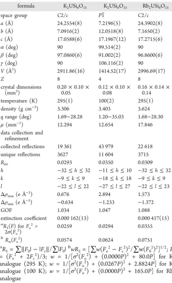
Crystallographic data are provided in Table 1. Phase purity of samples
used for physical properties measurements was checked using powder X-ray diffraction. Data were collected on a Rigaku Ultima IV di ff ractometer with a Cu K α source ( λ = 1.540 56 Å) and a scintillation counter. Energy-dispersive X-ray spectroscopy, EDS, was performed on single crystals of A
2USi
6O
15(A = K, Rb) using a TESCAN Vega-3 SBU equipped with an EDS detector. EDS data confirmed the presence of A, U, Si, and O and found no evidence of any F or Cl being present in the crystals, despite being present in the flux.
Figure 1. Single crystals of (a) K
2USi
6O
15and (b) Rb
2USi
6O
15.
Table 1. Crystallographic Data for A
2USi
6O
15(A = K, Rb)
formula K
2USi
6O
15K
2USi
6O
15Rb
2USi
6O
15space group
C2/c P1̅ C2/ca
(Å) 24.2554(8) 7.2196(5) 24.3902(8)
b
(Å) 7.0916(2) 12.0518(8) 7.1650(2)
c
(Å) 17.0588(6) 17.1967(12) 17.2715(6)
α
(deg) 90 99.514(2) 90
β
(deg) 97.0860(6) 91.002(2) 96.8600(6)
γ
(deg) 90 106.116(2) 90
V
(Å
3) 2911.86(16) 1414.52(17) 2996.69(17)
Z
8 4 8
crystal dimensions (mm
3)
0.20
×0.10
×0.05
0.12
×0.10
×0.08
0.16
×0.14
×0.14
temperature (K) 295(1) 100(2) 295(1)
density (g cm
−3) 3.306 3.403 3.624
q
range (deg) 1.69
−28.28 1.20
−35.03 1.68
−28.30
μ
(mm
−1) 12.294 12.654 17.846
data collection and re
finement
collected re
flections 19 361 43 979 22 618
unique re
flections 3627 11 604 3715
Rint
0.0293 0.0350 0.0309
h −32≤h≤
32
−11≤h≤10
−32≤h≤32
k −
9
≤k≤9
−18
≤k≤18
−9
≤k≤9
l −
22
≤l≤22
−27
≤l≤27
−22
≤l≤23
Δρmax
(e Å
−3) 0.676 2.894 1.573
Δρmin
(e Å
−3)
−0.634
−1.233
−1.372
GOF 1.034 1.047 1.088
extinction coe
fficient 0.000 162(13) 0.000 417(15)
aR1
(F) for
Fo2>
2σ(F
o2)
0.0259 0.0294 0.0355
bRw
(F
o2) 0.0574 0.0624 0.0751
a