Publisher’s version / Version de l'éditeur: HVAC and R Research, 19, 1, pp. 10-23, 2013-01-10
READ THESE TERMS AND CONDITIONS CAREFULLY BEFORE USING THIS WEBSITE.
https://nrc-publications.canada.ca/eng/copyright
Vous avez des questions? Nous pouvons vous aider. Pour communiquer directement avec un auteur, consultez la première page de la revue dans laquelle son article a été publié afin de trouver ses coordonnées. Si vous n’arrivez pas à les repérer, communiquez avec nous à [email protected].
Questions? Contact the NRC Publications Archive team at
[email protected]. If you wish to email the authors directly, please see the first page of the publication for their contact information.
NRC Publications Archive
Archives des publications du CNRC
This publication could be one of several versions: author’s original, accepted manuscript or the publisher’s version. / La version de cette publication peut être l’une des suivantes : la version prépublication de l’auteur, la version acceptée du manuscrit ou la version de l’éditeur.
For the publisher’s version, please access the DOI link below./ Pour consulter la version de l’éditeur, utilisez le lien DOI ci-dessous.
https://doi.org/10.1080/10789669.2012.730856
Access and use of this website and the material on it are subject to the Terms and Conditions set forth at
Convective heat transfer correlations for low-profile spherical cavities
with planar bottom surfaces (1415-RP)
Saber, Hamed H.; Laouadi, Abdelaziz; Galasiu, Anca D.; Arsenault, Chantal
https://publications-cnrc.canada.ca/fra/droits
L’accès à ce site Web et l’utilisation de son contenu sont assujettis aux conditions présentées dans le site LISEZ CES CONDITIONS ATTENTIVEMENT AVANT D’UTILISER CE SITE WEB.
NRC Publications Record / Notice d'Archives des publications de CNRC:
https://nrc-publications.canada.ca/eng/view/object/?id=e4be978e-99a2-4d09-b815-44e250513a24 https://publications-cnrc.canada.ca/fra/voir/objet/?id=e4be978e-99a2-4d09-b815-44e250513a24
Convective Heat Transfer Correlations for Low-Profile Spherical
Cavities with Planar Bottom Surfaces (1415-RP)
Hamed H. Saber1, Abdelaziz Laouadi, Anca D. Galasiu, and Chantal Arsenault
NRC Construction Portfolio, National Research Council Canada
Bldg. M-24, 1200 Montreal Road, Ottawa, Ontario, Canada K1A 0R6
http://irc.nrc-cnrc.gc.ca/irccontents.html
ABSTRACT
Domed cavities are found in many building applications such as conventional skylights and tubular daylighting devices. Heat transfer through domed cavities is thus an important parameter for evaluating the energy performance rating of such skylight systems, and in calculating the heating and cooling loads of buildings. Although there have been many studies on the convective heat transfer in related geometries, there is a limited information on natural convective heat transfer in domed cavities with planar inner surfaces. In a previous study by the authors, a numerical modeling was conducted on natural laminar convective heat transfer in horizontal high-profile domed cavities with planar inner surfaces. In this paper, the pervious study is extended to investigate the natural convective heat transfer in horizontal low-profile spherical cavities with planar inner surfaces. The bounding surfaces are subject to uniform temperature conditions. The numerical model is based on the finite element method. The results show that for different boundary temperature conditions, the airflow in the cavities is mono-cellular and reaches steady state conditions for both cold and hot weather conditions. The numerical results are used to develop practical correlations for the Nusselt number in terms of Rayleigh number.
Keywords: Natural laminar convection, spherical cavity, domed cavity, skylight, tubular daylighting device.
INTRODUCTION
Domed cavities are found in many applications in buildings, particularly in conventional skylights and Tubular Daylighting Devices (TDD’s). Skylights and TDD’s are used mainly to daylight interior spaces, and therefore reducing lighting energy use. However, these systems may introduce a significant amount of heat loss (winter condition) and unwanted solar heat gain (summer condition) into indoor environment that might off-set their energy saving benefits. Heat transfer through domed cavities is thus an important factor in evaluating the energy performance rating of such skylight systems, and in calculating the heating and cooling loads of buildings. Although there have been many studies on the convective heat transfer in related geometries such as concentric domes, spheres and cylinders, there is limited information on natural convective heat transfer in domed cavities with planar inner surfaces.
A number of studies have addressed the heat transfer in related geometries such spheres and cylinders. The flow pattern between concentric isothermal spheres with diameter ratio of 2 was studied by Garg (1991). That study used the vorticity-stream-function formulation and a finite difference method to obtain the flow and temperature fields, which were in good agreement with previous experimental work. Chiu and Chen (1996a, 1996b) and Chen (2005) applied the same numerical method to study the transient natural convection between concentric and vertically eccentric spheres with diameter ratio of 2 under isothermal and mixed boundary conditions. The obtained numerical results for the flow pattern were consistent with the previous experimental work. McGowan et al. (1998) conducted measurements and numerical simulations using a commercial CFD package to investigate the thermal performance of pyramidal and barrel vault skylights. They concluded that the convective heat transfer in curved or trapezoidal cavities can be approximated using the correlations for flat rectangular cavities at the equivalent mean slope
of the complex cavity. The conclusion drawn from their study is, however, limited to fairly small Rayleigh numbers (Ra < 7x10⁴), and therefore, their results cannot be generalized to higher
Rayleigh numbers and to other geometry types.
Klems (2000) conducted measurements of the net heat flow through several types of flat and domed skylights. He compared the measured U-values with calculations using WINDOW 4 and THERM programs. The calculated U-factors did not agree with the measurements; in general, the measured U-factors were higher than the calculated ones. The disagreement between measurements and calculations was worse if the well air temperature (rather than the chamber air temperature) was used to calculate the measured U-factor. Klems (2000) pointed out the importance of having an accurate model of the frame and the environmental conditions.
Fomichev and Curcija (2007) used a CFD commercial tool to investigate free convection in multi-layer eccentric domes tilted from the horizontal. Correlations for Nu were developed for two types of domes with circular and flat inner surfaces tilted at 20º and 90º. The obtained correlations are limited to small range of Rayleigh number (Ra ≤ 7x10⁴). Sartipi et al. (2007)
conducted numerical simualtions using control volume approach to investigate free convection in eccentric multi-layer domes with low- and high-profiles when heated from the exterior surface. Profiles of Nusselt number (Nu) as a function of Rayleigh number (Ra) were developed for various dome shapes. Laouadi and Atif (2001) and Sartipi et al. (2010) used the numerical control volume approach to investigate the laminar natural convection within concentric domed cavities. The study covered a number of cavity gap spacing to dome radius ratios under a wide range of Rayleigh numbers. The numerical results were used to develop practical correlations for the heat transfer coefficient as a function of the cavity gap spacing to dome radius ratios and Ra.
The present study is a part of an ASHRAE research project (1415-RP) to evaluate the thermal performance of tubular daylighting devices. The study addresses numerically the laminar natural convection heat transfer in cavities of horizontal domes with planar inner surfaces subject to cold or hot uniform temperature boundary conditions. Saber and Laouadi, (2011) have recently studied natural convection heat transfer in horizontal fully-hemispheric domed cavities with planar inner surfaces. Their numerical model was based on the finite element method. The bounding surfaces of the cavity were subject to uniform temperatures during hot and cold weather conditions. The model was successfully benchmarked by comparing its predictions against numerical data available in literature for concentric spheres and domed cavities (Laouadi and Atif, 2001, Sartipi et al., 2007). Furthermore, Saber and Laouadi (2011) developed practical correlations for the convective heat transfer, covering broad ranges of the governing parameters in both cold and hot weather conditions.
The main objective of this paper is to extend the study by Saber and Laouadi (2011) to investigate the flow pattern within horizontal low-profile domed cavities with planar inner surfaces, and to develop heat transfer correlations that account for different environmental boundary conditions and cavity dimensions.
MATHEMATICAL FORMULATION
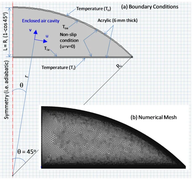
A domed cavity is bounded by two finite surfaces: an upper low-profile spherical surface (with a truncation angle of 45) at the top and an inner planar surface at the bottom. Both surfaces are made of a 6 mm (1/4 inch) acrylic sheets. The indoor side of the planar surface and outdoor side of the spherical surface are maintained at uniform temperatures Ti and To,
respectively. Owing to the temperature differential across the cavity (Ti– To), a buoyancy-driven
axi-symmetric since this configuration is axi-symmetrical with respect to the vertical revolution axis. Only half of the cavity is, therefore, considered for the numerical simulation. Figure 1a shows a schematic representation of the domed cavity.
Assumptions
The following assumptions are made for the air inside the cavity:
The long-wave radiation heat transfer between the cavity surfaces is decoupled from the convective heat transfer, and therefore is not accounted for in this study. This approach has been successfully applied to natural flows in enclosed cavities.
The air is incompressible.
The buoyancy-driven flow within the cavity is laminar.
The physical properties of the air are constant, except for density in the body force terms in the momentum balance equations. The physical properties of the air inside the cavity are evaluated at the average temperature of the bounding surfaces.
The fluid density is given by the Boussinesq approximation.
The compression work and the viscous dissipation energy in the energy balance equation are neglected.
Using the Boussinesq approximation, the fluid density is expressed as follows:
1 ( ref )
ref
a TT
(1)
The buoyancy-driven flow in the cavity is governed by the Navier-Stokes equations. The transient conservation equations for mass, momentum and energy in the spherical coordinate system read as follows:
0 ) sin ( sin 1 ) ( 1 2 2 u r v r r r a a (2)
Momentum balance in r-direction:
r a vt v rv ur v pr vS 2 (3)
Momentum balance in -direction:
p u S r u r u r u v t u a 1 2 (4) Energy balance (air):
T k T r u r T v t T cpa a a , 2 (5)
Energy balance (acrylic sheets):
T k t T cp s s s , 2 (6)
where 2is the Laplace operator, and S
rand Sare source terms. These are given by:
) (sin sin 1 ) ( 1 2 2 2 2 r r r r r (7) cos 1 2 2 2 22 2 2 cot r u u r r v u r g Sr a a (8) 2 2 ) sin ( 2 1 sin r u v r v u r g S a a (9)
Initial and Boundary Conditions
For the horizontal low-profile domed cavity shown in Figure 1a, the radial symmetry allows modelling a three-dimensional case in two-dimensions. The initial temperature and velocity
components are assumed equal to 10oC (50oF) and 0oC (32oF), respectively, everywhere in the
computational domain. The momentum equations are subjected to the no-slip condition at the air-solid interfaces (u v0), and symmetry condition at the axis of revolution (
u
0
and
/v = 0). The energy equations of both air and solid are subjected to the symmetry condition at the axis of revolution ( /T
= 0), and uniform temperatures at the indoor surface of the bottom planar acrylic sheet (T = Ti) and the outdoor surface of the spherical acrylic sheet (T =T0). Due to the energy balance at the air-solid interfaces, these interfaces are subjected to the
continuity condition (i.e. the heat fluxes in the air and solid normal to these interfaces are equal, and also the temperatures of air and solid are equal). Finally, in order to cover a wide range of the temperature difference across the domed cavity, the temperature at the indoor surface of the bottom planar acrylic sheet is fixed at 21oC (69.8ºF) (indoor temperature), and the temperature at
the outdoor surface of the spherical acrylic sheet is taken in the range of 21.1oC (69.98ºF) to
70oC (158ºF) for the summer conditions, and -35oC (-31ºF) to 20oC (68ºF) for the winter
conditions.
NUMERICAL PROCEDURE
The present model was used to solve the governing equations (2) to (6), subjected to the boundary conditions described above. The numerical procedure in this study is similar to the pervious study (Saber and Laouadi, 2011). The present model was benchmarked and used in several tasks to predict the hygrothermal (moisture transport is accounted for) performance of different building envelope components (Saber et al., 2010a, 2010b; 2010c; 2010d; 2011, 2012a, 2012b). To assure that the results are mesh independent, a non-uniform mesh was selected with finer sizes near the boundaries. Typically, the numerical mesh was refined by doubling the
number of nodes until the final results do not appreciably change. Triangular elements were chosen to capture the curved computational domain with less discritizing error. Figure 1b shows a typical mesh used through the simulations.
CONVECTIVE HEAT TRANSFER IN THE DOMED CAVITY
The enclosed airspace in the horizontal domed cavity is subjected to a buoyancy-induced flow. In this study, five of inner radii (Ri) were selected for the simulation: Ri= 0.5 m (1.64 ft),
0.63 m (2.067 ft) , 0.75 m (2.46 ft), 0.88 m (2.89 ft), and 1.0 m (3.28 ft). Based on the set of typical boundary conditions, the expected range of temperatures on the acrylic surfaces were considered so that standard investigation of a convective heat transfer in cavity, subject to temperature boundary conditions on its bounding surfaces, can be defined. This approach allows the development of dimensionless setup of the problem where dimensionless convective heat transfer rates, as expressed by Nusselt number, Nu, can be evaluated as a function of dimensionless natural convection parameter Raleigh number, Ra.
There are two options to be used in applying temperature boundary conditions on the domed cavity. The first option is to assume that the temperatures on the indoor surface (facing the indoor environment) of the bottom planar acrylic sheet (Ti) and the outdoor surface (facing the
outdoor environment) of the top spherical acrylic sheet (To) are uniform. The second option is to
assume that the temperatures of the surfaces of the top and bottom sheets in contact with the cavity air (Toa and Tia, respectively; see Figure 1a) are uniform. The second option was
extensively used in the literature where there is no need to include the walls in the numerical simulations (Laouadi and Atif, 2001; Sartipi et al., 2010). Due to the buoyancy-induced flow, the air movement inside the cavity would cause a non-uniform temperature distribution on the surfaces of the acrylic sheets facing the cavity air (Tiaand Toa). In a previous study (Saber and
Laouadi, 2011), it was shown that the temperature distribution on the surface facing the air cavity of the bottom acrylic sheet changed significantly in the case of cold weather, but it was approximately uniform except at the edges under the hot weather conditions. Consequently, the approach used in this study was to include the acrylic walls in the numerical simulations and apply uniform temperature boundary conditions on the surfaces facing the indoor and outdoor environments.
Evaluation of Nusselt Number
Under steady state conditions, the heat transfer rates at the boundary surfaces of the bottom and spherical acrylic sheets are equal due to the energy balance. Because of the heat loss/gain at the edges of the cavity, the heat transfer rates at the surfaces facing the air cavity of the bottom and top acrylic sheets are not equal. In this work, the Nusselt number, Nu, is defined as follows:
cond conv Q Q
Nu / (10)
where Qconv and Qcond are the convective heat transfer rate and the conductive heat rate in the absence of convection, respectively, normal to the inner surface (facing the air cavity) of the top spherical acrylic sheet.
To evaluate the Nu in equation (10), the conductive heat transfer rate in the absence of convection, Qcond, should be known a priori. Since there is no analytical solution available for
cond
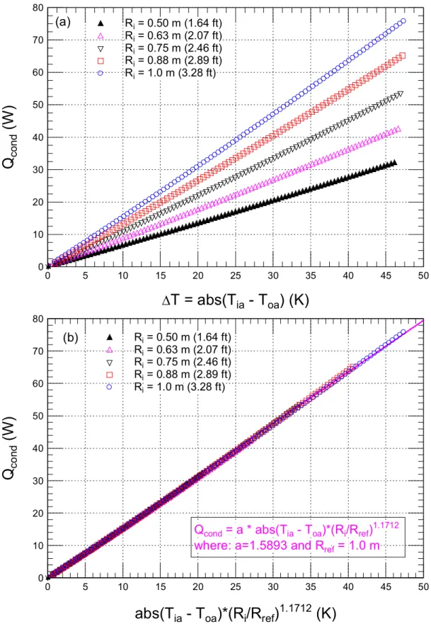
Q in such spherical cavities with two media (fluid and solid), a parametric study was conducted using the present model in order to calculate Qcond at different temperature differences across the cavity with different inner radii. The obtained results of Qcond are shown in Figure 2a. These results were used to develop a simple correlation for Qcond, which is given as:
i ref
ia oa
cond R R absT T Q 1.5893 / 1.1712 (11) ' ' ) ,' ( sin 2 ' sin 0 2 2 T r r dr R T i R r i ia
and (1 cos ) ( , ) sin .
1 0 d R T Toa i
(12)Where 'r is the local radius of the inner surface of the planar acrylic, and T ,ia Toa are the area-weighted average temperatures at the surfaces facing the air cavity of the bottom and top acrylic sheets, respectively. These area-weighted average temperatures were obtained by numerical integration of the nodal temperatures along the surfaces (see Eq. (12)). It is important to point out that the angle in Eq. (12) must be greater than zero so that there is spherical dome. Also, the heat transfer correlations that are developed in this paper are applicable only for the case of horizontal spherical domed cavity with = 45o(see Figure 1).
In Eq. (11), Rref is a reference radius, which was taken equal 1.0 m in this study. As shown in Figure 2b, the obtained correlation given by Eq. (11) is in good agreement with the numerical results. It should be noted that this correlation is developed when the SI units are used for the heat flux and temperature.
RESULTS AND DISCUSSIONS
All results presented in this paper are for the case when air fills the cavity. The physical properties of the air are evaluated at the mean temperature of the air in the cavity. During the transient regime, a multi-cellular airflow with different number of vortex cells were observed for both the winter (Ti > To) and summer (Ti< To) conditions. At steady state conditions, however,
a mono-cellular airflow (i.e. the number of vortex cells in the air cavity = 1) was observed in both cases of hot and cold weather conditions. Furthermore, a number of numerical simulations
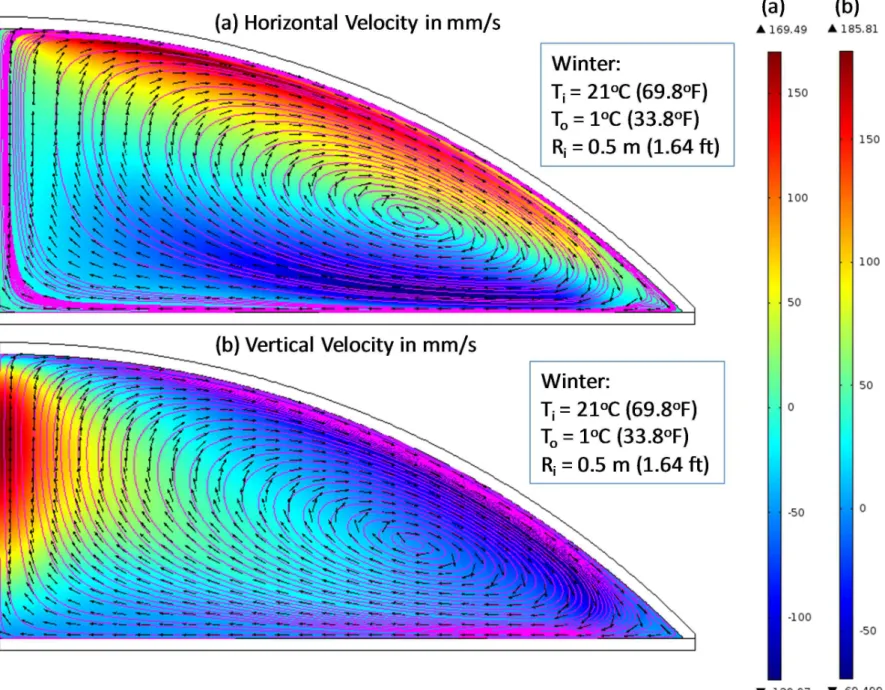
are conducted with different initial temperatures for each cavity configuration. The results show that both the flow characteristics and calculated Nu at steady state conditions are independent on the initial temperatures for both cold and hot weather conditions. Examples of the temperature contours, velocity contours, velocity vectors, and streamline for both hot and cold weathers are presented in Figure 3 to Figure 6 at steady state condition for a typical cavity configuration with an inner radius of 0.5 m (1.64 ft) when the absolute temperature difference across the cavity is equal to 20 K (36 ºR).
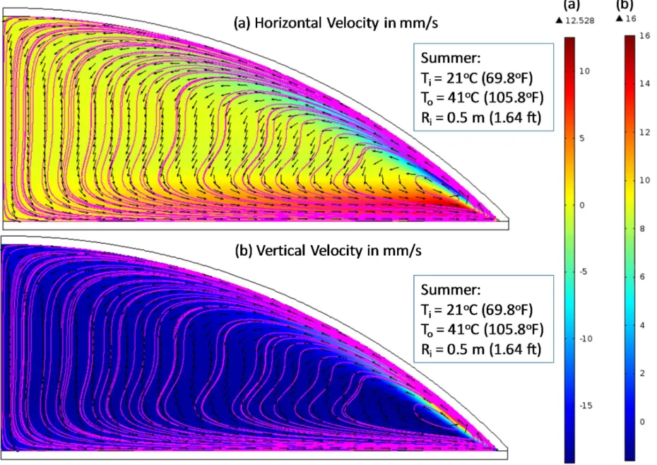
Figure 3a and Figure 3b show the horizontal and vertical velocity contours, velocity vectors, and streamline in the case of cold weather at steady state conditions. Also, Figure 4a and Figure 4b show the horizontal and vertical velocity contours, velocity vectors, and streamline in the case of hot weather. As shown in these figures, only one vortex cell was observed in both hot and cold weathers. However, both the horizontal and vertical velocities were much higher in the case of cold weather than that in the case of hot weather. For example, for the same temperature difference across the cavity, the maximum absolute horizontal and vertical velocities in the case of cold weather were 169.5 mm/s (2002 ft/h) and 185.8 mm/s (2194 ft/h), respectively, which were 8.8 and 11.6 times higher than that in the case of hot weather (19.3 mm/s (227 ft/h), 16 mm/s (188 ft/h), respectively). As such, for the same temperature difference across the cavity, the heat transfer coefficient for cold weather is significantly higher than warm weather. The heat loss/gain on the other hand will also depend on the temperature difference between the inside and the outside.
Figure 5a and Figure 5b show the temperature contours without (pure conduction) and with convection, respectively, in the case of cold weather. Figure 6a and Figure 6b show the temperature contours without and with convection, respectively, in the case of hot weather. As
shown in these figures, the buoyancy-induced flow results in a significant effect on the temperature distribution in the cavity in both cold and hot weather conditions.
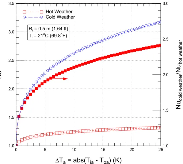
Figure 7 shows the dependence of Nu at the inner surface (facing air cavity) of the top spherical acrylic sheet on the absolute temperature difference across the cavity,
) ( ia oa a abs T T
T
, under the cold and hot weather conditions. Nu increases significantly with increasing Ta under the cold weather conditions. Under the hot weather, however, Nu increases with increasing Ta at a much lower rate. Additionally, for the same , the Nu is Ta much higher under the cold weather condition than under the hot weather condition. For example, Nu under the cold weather condition is 1.67 and 2.33 times higher than Nu under the hot weather condition for Ta = 2 K (3.6 oR) and 20 K (36 oR), respectively. As stated earlier,
this is due to higher air velocities under the cold weather condition than under the hot weather condition for the same Ta across the cavity.
Correlations for the Convective Heat Transfer
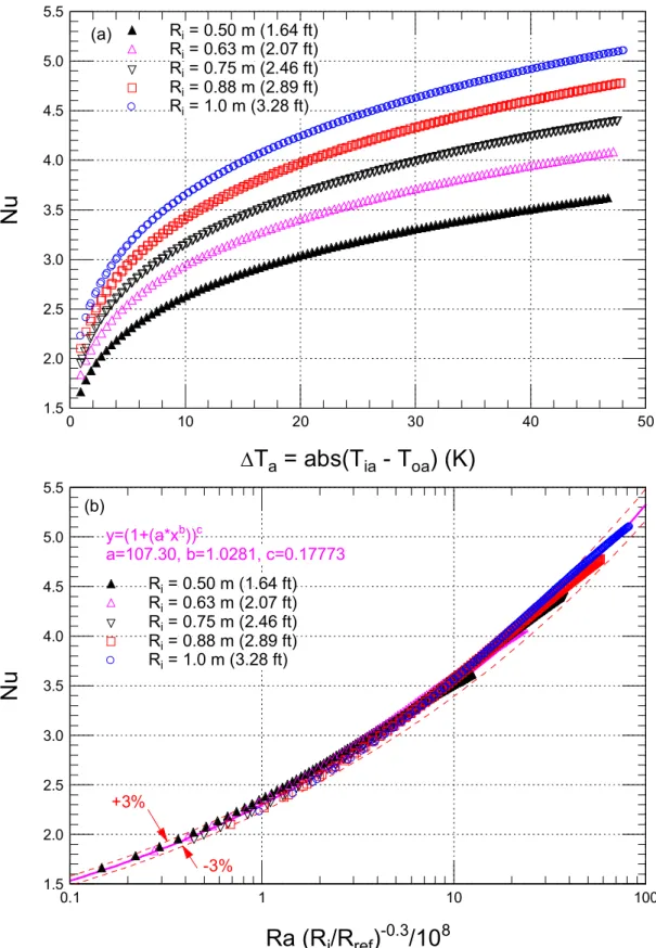
Figure 8a and Figure 8b show the effect of the temperature difference across the cavity , Ta and Ra on Nu under the cold weather conditions (Ti > To), respectively. For the same inner
radius, increasing Ta results in a stronger convection current in the cavity. As such,
Nu
increases by increasing Ta (see Figure 8a). Additionally, for the same , Ta Nu increases by increasing the inner radius of the cavity. For example, at Ta = 10 K (18 oF),
Nu
is 2.62 and3.64 for a cavity of radius Ri= 0.5 m (1.64 ft) and 1.0 m (3.28 ft), respectively. The numerical
cold weather condition. A power-law form is used to develop this correlation. The obtained correlation is given as follows:
( / ) /10
, a=107.3, b=1.0281, c=0.17773 1 0.3 8 c b ref i R R Ra a Nu (13)Where Ra is expressed as follows:
g Tia Toa Ri3 Ra (14)
In this correlation, Ra was evaluated using the air properties at the mean temperature of the air inside the cavity. Also, the characteristic length that was used to define Ra is the inner radius of the air cavity (Ri). However, in the case of using the maximum height of the air cavity at the
axis of revelation (L, see Figure 1) as a characteristic length to define the Rayleigh number (Ra* in this case), Ra in Eq. (13) must be replaced by Ra*/(1-cos())3, where = 45o. As shown in
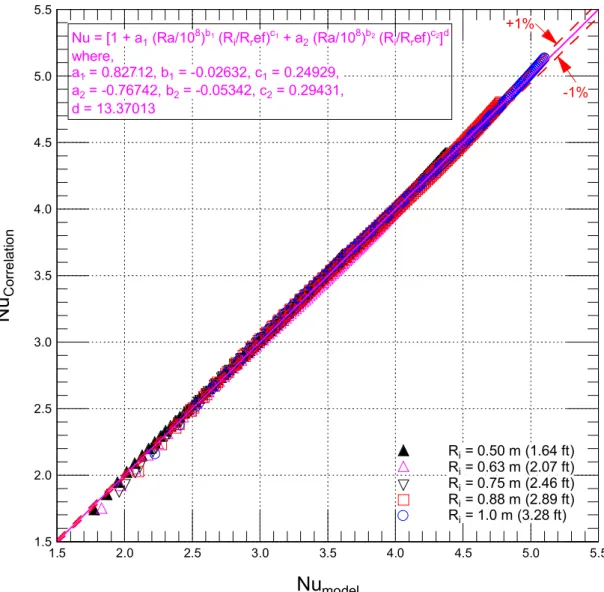
Figure 8b, the obtained correlation given by Eq. (13) is in good agreement with numerical results for different inner radii of the spherical cavities (within ±3%). A more accurate correlation for the Nu in the case of cold weather condition was also developed. This correlation is given as:
13.37013 , 0.29431 , -0.05342 , -0.76742 , 0.24929 , -0.02632 , 0.82712 , ) / ( ) 10 / ( ) / ( ) 10 / ( 1 2 2 2 1 1 1 8 2 8 1 1 1 2 2 d c b a c b a R R Ra a R R Ra a Nu b i ref c b i ref c d (15)Figure 9 shows that the calculated Nu using the above correlation (Eq. (15)) is in good agreement with that obtained using the present model (within ±1%).
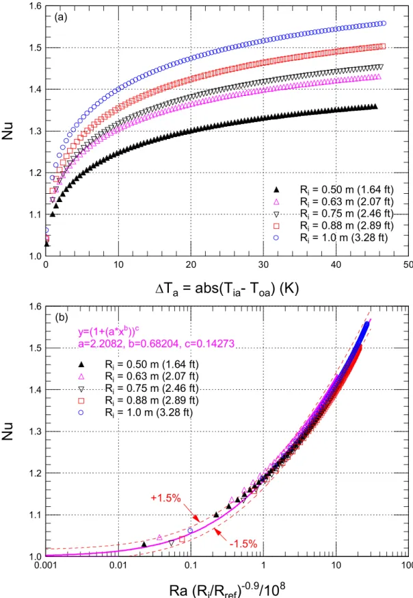
Under the hot weather condition (i.e. Ti< To), the effect of Ta and
Ra
onNu
are shownin Figure 10a and Figure 10b, respectively. The results shown in Figure 10a are collapsed to obtain the following correlation:
( / ) /10
, a=2.2082,b=0.68204, c=0.14273 1 a Ra Ri Rref 0.9 8b cNu (16)
Similar to Eq. (13), Ra in Eq. (16) must be replaced by Ra*/(1-cos())3in the case of using
the height of the cavity at the axis of revelation (L) as a characteristic length to define Ra*. As shown in Figure 10b, the developed correlation given by Eq. (16) is in good agreement with numerical results for different radiuses of the air cavities (within ±1.5%). Note that in both correlations for the cold and hot weather conditions, Nu approaches to 1.0 as the value of Ra goes to zero. Also, a more accurate correlation in the case of hot weather condition was developed where Nu obtained using this correlation is in good agreement with that obtained using the present model (within ±1%, see Figure 11). This correlation is given as:
25437 . 3 , 10044 . 0 , 0301 . 0 , 05341 . 0 , 15528 . 0 , 19644 . 0 , 0.10622 , ) / ( ) 10 / ( ) / ( ) 10 / ( 1 2 2 2 1 1 1 8 2 8 1 1 1 2 2 d c b a c b a R R Ra a R R Ra a Nu b i ref c b i ref c d (17)The convective heat transfer correlations for the cold weather and hot weather conditions (Eq. (13) or (15) and Eq. (16) or (17), respectively) were obtained when the temperature of the indoor side of the planar surface (Ti) equal to 21oC (69.8oF). In the cold weather condition, the
temperature range of the outdoor side of the spherical surface (To) was 20oC (68oF) to -35oC
(-31oF) (|Ti – To|min = 1 K (1.8 oR) and (|Ti – To|max = 56 K (100.8 oR)). In the hot weather
condition, however, the temperature range of the outdoor side of the spherical surface was 21.1oC (69.98oF) to 70oC (158oF) (|T
i – To|min= 0.1 K (0.18 oR) and (|Ti – To|max= 49.0 K (88.2 oR)). The range of the inner radius of the domed cavity (R
i) was varied from 0.5 m to 1.0 m. As
indicated earlier, a number of numerical simulations were conducted with different initial temperatures for each cavity configuration. In these simulations, the steady state conditions were achieved where the flow characteristics and calculated Nu were independent on the initial
temperatures for both cold and hot weather conditions. According to the definition of Ra number given by Eq. (14) where its characteristic length is equal Ri, the lowest and highest Ra in the case
of the air heated from below (cold weather condition) were 1.19 x 10⁷(R
i= 0.5 m (1.64 ft), and
|Ti– To| = 1 K (1.8 oR)) and 1.01x10⁹(Ri= 1.0 m, |Ti– To| = 56 K (100.8 oR)), respectively (see
Figure 12). When the height of the air cavity at the axis of revelation was taken as the characteristic length for Rayleigh number, the corresponding range for Ra* was 2.98 x 10⁵and
2.53 x 10⁷(Figure 12).
For this range Rayleigh number (Ra or Ra*), flow instabilities in the air cavity are not known (experimental data are not available), and were not observed using the present numerical approach. In flat horizontal cavities heated from below, flow instability due to the Rayleigh-Benard convection may occur at a lower Ra. For example, Bucchignani and Stella (1999) and Stella and Bucchignani (1999) found out that the critical Ra values depend on the problem parameters such as the Prandtl number (Pr), aspect ratio, and flow configurations. For their specific geometries, the critical Ra values corresponding to flow transition from a steady to unsteady state were found to vary from 3.4x10⁴to 4.4x10⁴. In the present study, flow instability
would occur at higher values of Rayleigh number since the curvature of the horizontal domed cavity helps to stabilise the flow (note that natural flows in vertical cavities are stable for this critical Ra range). Therefore, future experimental studies should be conducted in order to investigate the flow instability and transition in domed cavities.
CONCLUSIONS
A numerical model based on the finite element method was developed to study natural convection heat transfer in horizontal low-profile domed cavities with planar inner surfaces. The
hot and cold weather conditions. In a recent study (Saber and Laouadi, 2011), the model was successfully benchmarked by comparing its predictions against numerical data available in literature for concentric spheres and domed cavities with a uniform gap thickness. The results obtained for the domed cavity under consideration showed that at steady state conditions, a mono-cellular airflow was observed in both cases of hot and cold weather conditions. For the same temperature difference across the cavity, the airflow velocity was much higher under the cold weather condition than under the hot weather condition. Practical correlations for the convective heat transfer in the cavity were developed, covering broad ranges of governing parameters under both cold and hot weather conditions.
ACKNOWLEDGEMENT
This work was jointly funded by ASHRAE under the Research Project 1415-RP, and the NRC Construction Portfolio of the National Research Council of Canada. The authors are very thankful for their financial support.
NOMENCLATURE
Cp : specific heat (J/(kg.K))g : gravitational acceleration (m2/s)
L : length of the axis of revolution of the air cavity, L = Ri(1 – cos 45o) (m)
Nu : Nusselt number (-) p : pressure (Pa)
Pr : Prandtl number, Pr Cp / / Qeff : heat transfer rate (W)
Ri : inner dome radius (m)
Ro : outer dome radius (m)
Ra : Rayleigh number (-)
Ra* : Modified Rayleigh number, gTiaToa L3/() r : radial position (m)
Sr, S : source terms in the radial and circumferential directions.
T : temperature (ºC)
Ti : temperature of indoor surface of the bottom planar acrylic sheet of the cavity (K)
Tia : average temperature of the inner surface of the bottom planar acrylic sheet of cavity (K)
To : temperature of the outdoor surface of the top spherical acrylic sheet of cavity (K)
Toa : average temperature of the inner surface of top spherical acrylic sheet of cavity (K)
Tref : reference temperature equal to the average temperature of cavity bounding surfaces (K)
t : time (s)
u : velocity component in -direction (m/s) v : velocity components in r-direction (m/s)
Greek Symbols
: fluid thermal diffusivity (m2/s)
: thermal conductivity (W/(m.K))
: dimensionless cavity gap spacing ( = (Ro-Ri)/Ri)
: fluid thermal expansion coefficient (K-1)
: fluid dynamic viscosity (Pa.s) : fluid kinematic viscosity (m2/s)
: position angle : density (kg/m3)
ref : density evaluated at Tref(kg/m3)
Subscripts
a : air
s : solid
REFERENCES
Bucchignani, E. and Stella, F. 1999. Rayleigh – Benard Convection in Limited Domains: Part 2 – Transition to Chaos. Numerical Heat Transfer, Part A, 36: 17-34.
Chiu C.P. and Chen W.R. 1996a. Transient Natural Convection Heat transfer between Concentric and Vertically Eccentric Spheres. International Journal of Heat and Mass Transfer, 39/7: 1439-1452.
Chiu C.P. and Chen W.R. 1996b. Transient Natural Convection Heat Transfer between Concentric and Vertically Eccentric Spheres with Mixed Boundary Conditions. Journal of Heat and Mass Transfer, 31: 137-143.
Chen W.R. 2005. Transient Natural Convection of Micropolar Fluids between Concentric and Vertically Eccentric Spheres. Journal of Heat and Mass Transfer, 48: 1936-1951.
Fomichev A. and Curcija C.D. 2007. Development of a Procedure for U-Factor Rating of Domed Skylights. Final Report. University of Massachusetts. Massachusetts.
Garg V.G. 1991. Natural Convection between Concentric Spheres. International Journal of Heat and Mass Transfer, 35/8: 1935-1945.
Kelms, J.H. 2000. U-Values of Flat and Domed Skylights. ASHRAE 2000 Annual Meeting, June 24-28, 2000, Minneapolis, MN, and published in ASHRAE Transactions, 106 (2) 2000. Laouadi, A. and Atif, M.R. 2001. Natural Convection Heat Transfer within Multi-layer Domes.
International Journal of Heat and Mass Transfer, 44: 1973-1981.
McGowan, A.G., Desjarlais, A.O. and Wright, J.L. 1998. Simulation and Testing of Pyramid and Barrel Vault Skylights. ASHRAE Transactions, 104/1: 832-844.
Saber, H.H, and Laouadi, A. 2011. Convective Heat Transfer in Hemispherical Cavities with Planar Inner Surfaces (1415-RP). Journal of ASHRAE Transactions, Volume 117, Part 2, 2011
Saber, H.H., Maref, W., Elmahdy, A.H., Swinton, M.C., and Glazer, R. 2010a. 3D Thermal Model for Predicting the Thermal Resistances of Spray Polyurethane Foam Wall Assemblies. Building XI Conference, December 5-9, Clearwater Beach, Florida.
Saber, H.H., Swinton, M.C. 2010b. Determining through Numerical Modeling the Effective Thermal Resistance of a Foundation Wall System with Low Emissivity Material and Furred – Airspace. 2010 International Conference on Building Envelope Systems and Technologies, ICBEST 2010, Vancouver, British Colombia, Canada, June 27-30: 247-257.
Saber, H.H., Maref, W., Armstrong, M., Swinton, M.C., Rousseau, M.Z., and Gnanamurugan, G. 2010c. Benchmarking 3D Thermal Model against Field Measurement on the Thermal
Response of an Insulating Concrete Form (ICF) Wall in Cold Climate. Building XI Conference, December 5-9, Clearwater Beach, Florida.
Saber, H.H., Maref, M., Lacasse, M.A., Swinton, M.C., and Kumaran, M.K. 2010d.
Benchmarking of Hygrothermal Model against Measurements of Drying of Full-Scale Wall Assemblies. International Conference on Building Envelope Systems and Technologies, ICBEST 2010, Vancouver, British Colombia Canada, June 27-30: 369-377.
Saber, H.H., Maref, W., Swinton, M.C., and St-Onge, C. 2011. Thermal Analysis of Above-Grade Wall Assembly with low Emissivity Materials and Furred-Airspace. Journal of Building and Environment, (doi:10.1016/j.buildenv.2011.01.009), volume 46, issue 7, pp. 1403-1414, 2011.
Saber, H.H., Maref, W., Elmahdy, A.H., Swinton, M.C., and Glazer, R. 2012a. 3D Heat and Air Transport Model for Predicting the Thermal Resistances of Spray Polyurethane Foam Wall Assemblies. International Journal of Building Performance Simulation,
(http://dx.doi.org/10.1080/19401493.2010.532568), First published on: 24 January 2011 (iFirst), Vol. 5, No. 2, p. 75–91, March 2012.
Saber, H.H. 2012b. Investigation of Thermal Performance of Reflective Insulations for Different Applications. Journal of Building and Environment (doi:10.1016/j.buildenv.2011.12.010). vol 52, p. 32-44, 2012.
Sartipi, A., Laouadi, A., Naylor, D., and Dhib, R. 2007. Natural convective Heat Transfer within Vertically Eccentric Domed Skylight Cavities. Proceedings of Building Simulation
conference, China.
Sartipi, A., Laouadi, A., Naylor, D., and Dhib, R. 2010. Convective Heat Transfer in Domed Skylight Cavities. Journal of Building Performance Simulation, in press.
Stella, F., and Bucchignani, E. 1999. Rayleigh – Benard Convection in Limited Domains: Part 1 – Oscillatory Flow. Numerical Heat Transfer, Part A, 36: 1-16.
Figure 1. A schematic representation of a horizontal spherical domed cavity of 45owith a planar
Figure 2. Dependence of the conductive heat transfer rate normal to the inner surface of the top spherical acrylic sheet
0 10 20 30 40 50 60 70 80 0 5 10 15 20 25 30 35 40 45 50 Ri= 0.50 m (1.64 ft) Ri= 0.63 m (2.07 ft) Ri= 0.75 m (2.46 ft) Ri= 0.88 m (2.89 ft) Ri= 1.0 m (3.28 ft) (b)
Qcond= a * abs(Tia- Toa)*(Ri/Rref)1.1712
where: a=1.5893 and Rref= 1.0 m
abs(T
ia- T
oa)*(R
i/R
ref)
1.1712(K)
Q
co nd(W
)
0 10 20 30 40 50 60 70 80 0 5 10 15 20 25 30 35 40 45 50 Ri= 0.50 m (1.64 ft) Ri= 0.63 m (2.07 ft) Ri= 0.75 m (2.46 ft) Ri= 0.88 m (2.89 ft) Ri= 1.0 m (3.28 ft) (a)
T = abs(T
ia- T
oa) (K)
Q
co nd(W
)
Figure 3. Horizontal and vertical velocity contours, velocity vectors and streamlines in the case of cold weather with temperature difference across the cavity of 20 K (36oR)
Figure 4. Horizontal and vertical velocity contours, velocity vectors and streamlines in the case of hot weather with temperature difference across o
Figure 7. Dependence of Nusselt number on the temperature difference across the cavity of an inner radius of 0.5 m (1.64 ft) 1.0 1.5 2.0 2.5 3.0 3.5 0 5 10 15 20 251.0 1.5 2.0 2.5 3.0 Hot Weather Cold Weather Ri= 0.5 m (1.64 ft) Ti= 21oC (69.8oF)
T
a= abs(T
ia- T
oa) (K)
N
u
N
u
co ld w ea th er/N
u
ho t w ea th e rFigure 8. Dependence of Nu on the temperature difference across the cavity and Ra in the case of a cold weather condition
1.5 2.0 2.5 3.0 3.5 4.0 4.5 5.0 5.5 0.1 1 10 100 Ri= 0.50 m (1.64 ft) Ri= 0.63 m (2.07 ft) Ri= 0.75 m (2.46 ft) Ri= 0.88 m (2.89 ft) Ri= 1.0 m (3.28 ft) (b) +3% -3% y=(1+(a*xb))c a=107.30, b=1.0281, c=0.17773
Ra (R
i/R
ref)
-0.3/10
8N
u
1.5 2.0 2.5 3.0 3.5 4.0 4.5 5.0 5.5 0 10 20 30 40 50 Ri= 0.50 m (1.64 ft) Ri= 0.63 m (2.07 ft) Ri= 0.75 m (2.46 ft) Ri= 0.88 m (2.89 ft) Ri= 1.0 m (3.28 ft) (a)
T
a= abs(T
ia- T
oa) (K)
N
u
Figure 9. Comparison between Nu obtained using the developed correlation (Eq. (15)) and that obtained using the present model in the case of a cold weather condition
1.5 2.0 2.5 3.0 3.5 4.0 4.5 5.0 5.5 1.5 2.0 2.5 3.0 3.5 4.0 4.5 5.0 5.5 Ri= 0.50 m (1.64 ft) Ri= 0.63 m (2.07 ft) Ri= 0.75 m (2.46 ft) Ri= 0.88 m (2.89 ft) Ri= 1.0 m (3.28 ft) Nu = [1 + a1(Ra/108)b1(R
i/Rref)c1+ a2(Ra/108)b2(Ri/Rref)c2]d
where, a1= 0.82712, b1= -0.02632, c1= 0.24929, a2= -0.76742, b2= -0.05342, c2= 0.29431, d = 13.37013 +1% -1%
Nu
modelN
u
C or re la tio nFigure 10. Dependence of Nu on the temperature difference across the cavity and Ra in the case of a hot weather condition
1.0 1.1 1.2 1.3 1.4 1.5 1.6 0.001 0.01 0.1 1 10 100 Ri= 0.50 m (1.64 ft) Ri= 0.63 m (2.07 ft) Ri= 0.75 m (2.46 ft) Ri= 0.88 m (2.89 ft) Ri= 1.0 m (3.28 ft) (b) +1.5% -1.5% y=(1+(a*xb))c a=2.2082, b=0.68204, c=0.14273
Ra (R
i/R
ref)
-0.9/10
8N
u
1.0 1.1 1.2 1.3 1.4 1.5 1.6 0 10 20 30 40 50 Ri= 0.50 m (1.64 ft) Ri= 0.63 m (2.07 ft) Ri= 0.75 m (2.46 ft) Ri= 0.88 m (2.89 ft) Ri= 1.0 m (3.28 ft) (a)
T
a= abs(T
ia- T
oa) (K)
N
u
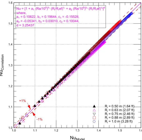
Figure 11. Comparison between Nu obtained using the developed correlation (Eq. (17)) and that obtained using the present model in the case of a hot weather condition
1.0 1.1 1.2 1.3 1.4 1.5 1.6 1.0 1.1 1.2 1.3 1.4 1.5 1.6 Ri= 0.50 m (1.64 ft) Ri= 0.63 m (2.07 ft) Ri= 0.75 m (2.46 ft) Ri= 0.88 m (2.89 ft) Ri= 1.0 m (3.28 ft)
Nu = [1 + a1(Ra/108)b1(Ri/Rref)c1+ a2(Ra/108)b2(Ri/Rref)c2]d
where, a1= 0.10622, b1= 0.19644, c1= -0.15528, a2= -0.05341, b2= 0.03010, c2= 0.10044, d = 3.25437 +1% -1%
Nu
ModelN
u
C o rr el a tio nFigure 12. Dependence of Nu on Ra and Ra* for a 45ospherical cavity (R
i= 0.5 m) in
the case of a cold weather condition
1.5 1.7 1.9 2.1 2.3 2.5 2.7 2.9 3.1 3.3 3.5 3.7 105 106 107 108 109 Based on Ra Based on Ra* Ri= 0.5 m (1.64 ft) Ti= 21oC (69.8oF) To= 20oC (68.0oF) to -35oC (-31.0oF)