Publisher’s version / Version de l'éditeur:
IEEE Sensors Journal, 6, 3, pp. 580-587, 2006-06-01
READ THESE TERMS AND CONDITIONS CAREFULLY BEFORE USING THIS WEBSITE. https://nrc-publications.canada.ca/eng/copyright
Vous avez des questions? Nous pouvons vous aider. Pour communiquer directement avec un auteur, consultez la
première page de la revue dans laquelle son article a été publié afin de trouver ses coordonnées. Si vous n’arrivez pas à les repérer, communiquez avec nous à PublicationsArchive-ArchivesPublications@nrc-cnrc.gc.ca.
Questions? Contact the NRC Publications Archive team at
PublicationsArchive-ArchivesPublications@nrc-cnrc.gc.ca. If you wish to email the authors directly, please see the first page of the publication for their contact information.
Archives des publications du CNRC
This publication could be one of several versions: author’s original, accepted manuscript or the publisher’s version. / La version de cette publication peut être l’une des suivantes : la version prépublication de l’auteur, la version acceptée du manuscrit ou la version de l’éditeur.
For the publisher’s version, please access the DOI link below./ Pour consulter la version de l’éditeur, utilisez le lien DOI ci-dessous.
https://doi.org/10.1109/JSEN.2006.874026
Access and use of this website and the material on it are subject to the Terms and Conditions set forth at
High temperature and broadband immersion ultrasonic probes
Ono, Yuu; Kobayashi, Makiko; Moisan, Jean-François; Jen, Cheng-Kuei
https://publications-cnrc.canada.ca/fra/droits
L’accès à ce site Web et l’utilisation de son contenu sont assujettis aux conditions présentées dans le site LISEZ CES CONDITIONS ATTENTIVEMENT AVANT D’UTILISER CE SITE WEB.
NRC Publications Record / Notice d'Archives des publications de CNRC:
https://nrc-publications.canada.ca/eng/view/object/?id=14a21372-5427-4cd5-b0f2-1933b15e2605 https://publications-cnrc.canada.ca/fra/voir/objet/?id=14a21372-5427-4cd5-b0f2-1933b15e2605
sol–gel-sprayed thick films as piezoelectric ultrasonic transducers (UTs) directly deposited onto steel buffer rods. They operate in pulse-echo mode at temperatures up to 500 C. The operating ul-trasonic frequency is between 5 MHz and 20 MHz, controlled by the film thickness. The ultrasonic thickness measurement of a steel plate with the probe fully immersed in molten zinc at 450 C was demonstrated using ultrasonic plane waves. For imaging purposes, the probing end of the steel buffer rod was machined into a semi-spherical concave shape to form an ultrasonic lens and achieve high spatial resolution with focused ultrasound in liquids. Ultrasonic surface and subsurface imaging using a mechanical raster scan of the focused probe in silicone oil at 200 C was also carried out. The importance of the signal-to-noise ratio (SNR) in the pulse-echo measurement is discussed.
Index Terms—High-temperature ultrasonic transducer (HTUT), immersion probe, sol–gel-spray technique, thick film, ultrasonic imaging.
I. INTRODUCTION
U
LTRASONIC pulse-echo techniques [1], [2] are often used to perform nondestructive testing and characterization of materials due to their simplicity, speed, economy, and capa-bility to probe interiors of opaque materials. Such techniques sometimes require ultrasonic transducers (UTs) of large band-width, high signal-to-noise ratio (SNR), and to operate at el-evated temperatures. Various efforts have been devoted to de-velop high-temperature (HT) piezoelectric UTs [3]–[15]. Com-mercially, several piezoelectric HTUTs are also supplied by sev-eral companies, such as Etalon (Lizton, IN), RD-Tech Panamet-rics-NDT (Waltham, MA), RTD (Rotterdam, The Netherlands), Ultran (Boalsburg, PA), and Ishikawajima Inspection and In-strumentation (Tokyo, Japan), etc. Most of these HTUTs use buffer rods (delay lines) to facilitate the fabrication or HT mea-surements and to increase the ultrasonic frequency bandwidth.Manuscript received June 15, 2004; revised April 6, 2005. This work is sup-ported by the NRC-NSC (Taiwan, R.O.C.) project and the Natural Sciences and Engineering Research Council of Canada. The associate editor coordinating the review of this paper and approving it for publication was Prof. Pavel Ripka.
Y. Ono, J.-F. Moisan, and C.-K. Jen are with the Industrial Materials Insti-tute, National Research Council Canada, Boucherville, QC J4B 6Y4, Canada (e-mail: yuu.ono@cnrc-nrc.gc.ca; jean-francois.moisan@cnrc-nrc.gc.ca; cheng-kuei.jen@cnrc-nrc.gc.ca).
M. Kobayashi was with the Department of Electrical and Com-puter Engineering, McGill University, Montreal, Quebec H3A 2A7, Canada. She is now with the Industrial Materials Institute, National Re-search Council Canada, Boucherville, QC J4B 6Y4, Canada (e-mail: makiko.kobayashi@cnrc-nrc.gc.ca).
Digital Object Identifier 10.1109/JSEN.2006.874026
ported examples were performing ultrasonic measurements in Canola oil at 125 C using a 1–3 PZT piezocomposite trans-ducer [14]; viewing under liquid sodium coolant in order to inspect in-vessel structures in nuclear reactor using lead zir-conate titanate (PZT) ceramics up to 220 C [12], lead zirzir-conate ceramics up to 285 C [4] or lithium niobate crystals up to 600 C [5]; and measuring deformation of workpieces in a hot isostatic pressure vessel using an aluminum nitride film trans-ducer at temperatures above 1000 C and pressures above 150 MPa [9]. For most of these HTUTs, the piezoelectric materials were bonded [4], [5], [12], [14] or deposited [9] onto the sub-strates. In this study, we present an alternative method to fabri-cate immersion HT ultrasonic probes using a sol–gel-spray tech-nique. Wall thickness measurements and ultrasonic imaging at temperatures up to 450 C will be demonstrated in ultrasonic pulse-echo technique.
II. FABRICATION
A piezoelectric bismuth titanate, (BIT), could be an attractive candidate for devices such as sensors and actu-ators operating at elevated temperatures due to its high resis-tivity and high Curie temperature (675 C) [13], [16], [17]. The BIT powder was dispersed into PZT solution by a ball milling method to achieve the gel. An air gun was then used at room temperature to spray the sol–gel BIT/PZT composite directly onto metallic substrates, which can have a flat or curved surface. Spray conditions, such as air pressure, distance, and angle of the air gun to the substrate, and spray time were carefully adjusted to achieve homogeneous films. After spray coating, thermal treat-ments of drying, firing, and annealing were carried out. Mul-tiple layers were made in order to reach the desired film thick-ness. The piezoelectric film operating at an ultrasonic frequency range from 5 to 20 MHz can be manufactured by controlling the total film thickness. For this investigation, BIT/PZT films of 90 m thickness were made. Films were then electrically poled using a corona discharge technique. Finally, a top electrode was fabricated on the BIT/PZT film. The detailed fabrication process can be found in [18].
Fig. 1 shows the BIT/PZT film with a top electrode fabricated on a steel buffer rod with a length of 51 mm. The diameters at the UT end and the probing end of the rod were 32 and 30 mm, respectively, in order that the periphery of the rod had a 2 taper angle from the UT to probing ends for assembling the rod in a holder with a good seal preventing the liquid contacting the film UT. We used a platinum film fabricated by vacuum sputtering or a silver paste via painting at room temperature to form the top
Fig. 1. Ultrasonic probe consisting of a BIT/PZT film deposited onto a steel buffer rod.
Fig. 2. Ultrasonic probe mounted in a holder.
electrode. The electrodes of the platinum and silver paste were tested, and their operating temperature could be above 500 C. However, our experiments showed that the platinum electrode had better performance than the silver paste in an aspect of en-durance at temperatures above 250 C. The detail will be dis-cussed later.
The platinum film of 0.1 m thick and 10 mm in diameter was fabricated at the center of the buffer rod as seen in Fig. 1. The optimum diameter of the top electrode for this UT in order to obtain the strongest ultrasonic signal was around 10 mm. A coaxial cable made of stainless steel with magnesium oxide in-sulators was used as an electrical cable. This coaxial cable is applicable up to 900 C. An alumina ceramic plate (6.35 mm thick and 21.6 mm in diameter) was used to press an inner lead of the coaxial cable on the platinum top electrode with three stainless steel screws. Thus, a steady electric contact between the inner lead and the top electrode and a perfect electric iso-lation between the top and bottom electrodes (steel buffer rod) were realized. The HT probe mounted in a stainless steel (S316) holder, which can seal the BIT/PZT film HTUT from liquids, is shown in Fig. 2.
In order to investigate ultrasonic performance of the HT probe at elevated temperatures, the probe shown in Fig. 2 was set in an electric resistance furnace and heated. Fig. 3(a) shows ultrasonic signals measured at 22 C and 450 C with the ultrasonic pulse-echo technique. The signal is the first round-trip echo reflected from the probing end shown in Figs. 1 and 2. Fig. 3(b)
Fig. 3. Ultrasonic performance of the HT probe in (a) time and (b) frequency domains at 22 C and 450 C.
presents the frequency spectrums of the shown in Fig. 3(a). The center frequency was 8 MHz and the 6-dB bandwidth was 4 MHz for the at 450 C. The signal strength of the at 450 C was 1.5 dB smaller than that at 22 C at 8 MHz. The SNR of more than 40 dB was obtained both at 22 C and 450 C. Such ultrasonic performance is sufficient for thickness measurements to be presented in Section III.
The SNR, which is one of the important parameters to eval-uate performance of ultrasonic probes, is defined as the strength of the echo reflected at the probing end over that of the unwanted echoes in the probe (buffer rod here). The undesired echoes are called “spurious signals” throughout this paper. The spurious signals mainly come from the following sources: mode conver-sion, wave reverberation and diffraction within the rod of finite diameter and specific shape and scattering echoes from random grains or voids in the rod materials. High SNR can make many practical ultrasonic monitoring applications feasible. We also fabricated a PZT/PZT film UT by the sol–gel-spray technique and compared its ultrasonic performance with that of BIT/PZT film UT. The PZT/PZT UT had about 10 dB stronger ultrasonic signals than the BIT/PZT UT. The SNR of the PZT/PZT UT was almost the same as that of the BIT/PZT UT. However, operation temperature of the PZT/PZT UT was limited up to 200 C.
In order to test their durability, the HT probes were submitted to thermal cycles between room temperature and elevated tem-peratures using a furnace. During each thermal cycle, it took about 1 h to heat the probe from room temperature to elevated
thermal expansion coefficients of the materials; improper con-tact of an electrical cable onto the top electrode; and/or deterio-ration of piezoelectricity of the BIT/PZT film because of minor depoling at elevated temperatures.
III. ULTRASONICTHICKNESSMEASUREMENT OF ASTEEL
PLATE INMOLTENZINC AT450 C
Galvanization is one of common techniques to prevent corrosion of steel components. The steel parts are dipped into molten zinc (Zn) at temperatures 450 C–460 C for coating. The molten Zn is contained in a steel kettle with a size of, for example, 6 3 1 m. There is a concern that the kettle will corrode from the inside and might cause disastrous failure in which the dangerous and costly spillage of the molten Zn happens. Ideally, the kettles are heated uniformly and there is a gradual loss of the kettle wall thickness as an iron–Zn layer forms on the inside of the kettle. However, nonuniform heating of the burners and the build-up of dross at the bottom of the kettle can lead to accelerated corrosion. Therefore, the kettle is required to be examined periodically to ensure its safe operation. Previously, an electromagnetic acoustic transducer (EMAT) was used to show the feasibility to measure the wall thickness at the external side of the kettle wall [19]. However, a mechanical raster scanning of the EMAT to perform the wall thickness profile could be difficult since furnaces are installed near the external wall of the kettle.
In our previous work, we performed ultrasonic measurements and imaging in a molten Zn bath using long buffer rods [20]. However, the UT was outside of the molten Zn, and the UT was cooled by compressed air. Here, an immersion HT probe described above with a compact size as an alternative approach was used. The advantage is that this probe of light weight can be easily scanned inside the molten Zn, which acts as a liquid couplant between the probing end and the inner kettle wall to obtain the wall thickness profile.
Fig. 4 shows a schematic diagram of the ultrasonic thickness measurement in molten Zn using the pulse-echo technique. The purity of the Zn used was 99.5%. The reported longitudinal wave velocity and the density of the molten Zn at 420 C are 2790 m/s and 6.76 g/cm , respectively [21]. The HT probe shown in Fig. 2 was completely immersed into the molten Zn at 450 C together with a steel sample of a thickness of 24.5 mm. The distance between the probing end and the front surface of the sample was about 17 mm. The probe radiated and received pulsed ultrasound with a pulser–receiver. The Zn contained in a stainless steel (SS) crucible was heated by the furnace. A temperature controller controlled temperature of the molten
Fig. 4. Schematic diagram of ultrasonic thickness measurement of a 25.4-mm-thick steel plate in molten Zn at 450 C.
Fig. 5. Ultrasonic signals for thickness measurement in molten Zn at 450 C.
Zn using temperature values measured by a thermocouple immersed in the molten Zn. Ultrasonic signals were recorded using a data acquisition board with a resolution of 12 bits and a sampling rate of 100 MHz.
The ultrasonic thickness measurement in the molten Zn is given in Fig. 5. Two echoes, indicated by and , reflected from the front and back surfaces of the sample, respectively, were clearly observed. Provided that the longitudinal ultrasonic velocity in the steel at 450 C is known experimentally or from the literature, the thickness (H) of the sample can be cal-culated using the measured time delay difference ( , indicated in Fig. 5) between the and by . This steel probe was immersed in the molten Zn for many hours, and the
Fig. 6. Focused HT probe with an ultrasonic lens.
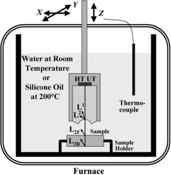
Fig. 7. Ultrasonic imaging setup.
probing end surface was only slightly corroded after even 9 h. It means that the surface remained acceptably flat. In fact, when this probe was placed facing the SS container, the wall thickness of the SS container could be measured as well.
IV. ULTRASONICIMAGING INSILICONEOIL AT200 C In order to achieve high spatial resolution, the probing end of the steel buffer rod of the HT probe shown in Fig. 1 was machined into a semispherical concave surface as an ultrasonic lens, which focuses ultrasound in liquids, as shown in Fig. 6. The radius of curvature and the aperture diameter of the lens were 11.1 and 14.9 mm, respectively. A schematic diagram of the ul-trasonic imaging set up in water at room temperature or in sili-cone oil at 200 C is shown in Fig. 7. The focused HT probe with a holder was mounted on a manual vertical-translation stage ( -stage) to adjust the distance between the probing end and the sample. In addition, the probe was transferred horizontally using an -stage driven by stepping-motors. A sample for imaging was fixed at the bottom of the crucible by a sample
Fig. 8. Optical photograph of U.S. one-cent coin used for imaging experiments. The tail side had its figures as an imaging side while the head side was polished to be flat.
holder. The data acquisition system was the same as the one used in Section III.
Fig. 8 shows an optical photograph of a sample used for imaging experiments, which was an American one-cent coin. The head side of the coin was polished to a flat surface while the tail side was left as it was for imaging. The diameter and thick-ness of the sample were 19.1 and 1.1 mm, respectively. The line thickness of the smallest characters
on the coin was about 0.2 mm.
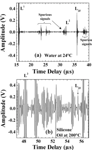
Fig. 9(a) shows the signals obtained when the front surface of the sample (figure side) was located at the focus of the lens in water at room temperature. The first and second round trip echoes of longitudinal waves in the rod were observed at the time delay of about 16 s and 32 s, respectively. The was a signal reflected from the front surface of the sample at the focus and used for constructing the surface images. Besides those signals, spurious signals caused by the semispherical sur-face of the lens can be seen. This semispherical sursur-face causes different ultrasonic wave path lengths, thus inducing spurious signals arrived at different time delays. If such spurious signals interfere with the desired signals from the sample, it may result in deterioration of imaging quality. The shown in Fig. 9(a) had enough SNR for constructing ultrasonic images in water at room temperature.
The signals obtained in silicone oil at 200 C when the front surface of the sample was located at the focus of the lens are presented in Fig. 9(b). The observed at 48 s was the third round-trip echo in the rod. The signals indicated in Fig. 9(b) was weak and about 20 dB smaller than that in water at room temperature under the same measurement conditions of electric energy applied to the UT and electronic amplification of the sig-nals. This is due to the following reasons: The ultrasonic atten-uation in silicone oil at 200 C is significant; and the acoustic impedance mismatching between the steel rod and silicone oil (200 C) is larger than that between the steel rod and water (24 C), resulting in less ultrasonic energy transmitted from the rod to silicone oil than to water.
In addition, the spurious signals in silicone oil at 200 C shown in Fig. 9(b) were much larger than those in water shown in Fig. 9(a) because of the 20-dB larger electronic amplification
Fig. 9. Reflected signals from the probe and the sample (a) in water at room temperature and (b) in silicone oil at 200 C.
of the signals than in water, which reduce the SNR of the . However, it is noted that amplitude and time delay of these spu-rious signals are fixed at a constant temperature because they are mainly the echoes reflected inside the rod. Therefore, such spurious signals can be eliminated significantly by subtracting background signals, measured without the sample, from the sig-nals measured with the sample by digital signal processing tech-niques. In the following imaging experiments, the data after the subtraction are presented. It is noted that the attenuation of ultra-sound in the steel rod at 200 C is negligible because the signal strength of the at 450 C was only 1.5 dB smaller than that at 22 C as shown in Fig. 3.
A. Surface Image
We evaluate the focusing ability of ultrasound in water at room temperature and in silicone oil at 200 C using this fo-cused HT probe at an ultrasonic frequency of 8 MHz in order to estimate spatial resolution for imaging in these liquids. The lateral resolution and focusing depth are approximately calculated using the following equations [22]:
(1) (2)
uids, is the focal length, and is the aperture diameter of the lens. The and are calculated by and , respectively, where and are longitudinal wave velocity in liquids and steel, respec-tively, and is a curvature radius of the lens. The calculated re-sults are summarized in Table I. The for water at 23 C is 1491 m/s [23], and the at 23 C and 200 C are 5923 and 5843 m/s [24], respectively. The for silicone oil at 200 C was estimated 612 m/s experimentally using the time delay of the signals reflected from the sample surface at the focus of the lens.
The in water (0.19 mm) is almost comparable to the smallest line thickness (0.2 mm) of the characters on the sample shown in Fig. 8. Due to the lower longitudinal wave ve-locity in silicone oil at 200 C (612 m/s) than in water at 23 C (1491 m/s), the higher lateral resolution 0.065 mm is expected in silicone oil. However, the acoustic impedance
of the silicone oil at 200 C is about 60% smaller than that of water, resulting in less transmission of ultrasonic energy from the steel rod to silicone oil than to water as mentioned previously, where is the density of the liquids that are almost the same between silicone oil and water. This causes the lower SNR of the desired signals in silicone oil than in water.
The imaging experiment was first carried out in water at room temperature, and then that in silicone oil (200 Fluid-100 cst, Dow Corning, Midland, MI) at 200 C using the same probe and sample. The sample shown in Fig. 8 was placed with the tail side (figure side) upward so that the figures were on the front surface and the back surface was flat. Fig. 10(a) and (b) shows the measured signals reflected from the sample in water at 24 C and in silicone oil at 200 C, respectively, when the front surface of the sample was placed at the focus of the lens. It is noted that subtraction of the background spurious noises had been conducted on the data, shown in Fig. 10, by the digital signal processing technique as mentioned previously. The time delay of the in silicone oil at 200 C was about 20 s greater than that in water at 24 C since ultrasonic velocity in silicone oil (612 m/s) is smaller than that in water (1491 m/s).
Fig. 11(a) and (b) shows ultrasonic images obtained in water at room temperature and in silicone oil at 200 C, respectively, using the signals shown in Fig. 10. The scan step was 100 m for raster scanning of the focused HT probe. The left and right figures were constructed from the amplitude and time delay of the , respectively. The darker color represents the larger amplitude for amplitude images and the longer time delay for time delay images. The images of the figures including the characters having 0.2-mm line thickness on the tail side of the one-cent coin were clearly observed. Slight deformation of
Fig. 10. Ultrasonic signals obtained when a front surface of the sample is at the focus of the lens (a) in water at room temperature and (b) in silicone oil at 200 C.
Fig. 11. Ultrasonic images of front surface of the sample measured (a) in water at room temperature and (b) in silicone oil at 200 C.
the images was caused by movement errors of the -stage used for raster scanning.
B. Subsurface Image
In order to investigate the performance of the focused HT probe for inspection of defects inside materials, experiments for subsurface imaging were carried out. The same sample used for the surface image was placed at the bottom of the crucible with the flat side upward so that the front surface was flat and the figure was on the back surface. Fig. 12(a) and (b) shows the measured signals reflected from the sample in water at 24 C
Fig. 12. Ultrasonic signals obtained when a back surface of the sample was at the focus of the lens (a) in water at room temperature and (b) in silicone oil at 200 C.
Fig. 13. Ultrasonic images of back surface of the sample measured (a) in water at room temperature and (b) in silicone oil at 200 C.
and in silicone oil at 200 C, respectively, when the back surface of the sample was placed at the focus of the lens. In addition to the reflected from the front surface of the sample, one can see the signals ( , ) reflected from the back surface of the sample in water and in silicone oil, where the and indicate the second and third round-trip signals, respectively, in the sample.
Fig. 13(a) and (b) shows ultrasonic images of the back surface (subsurface) of the sample obtained in water at 24 C and in silicone oil at 200 C, respectively, using the signals shown in Fig. 12. The subsurface images were observed in silicone oil
Thick-film (90 m) piezoelectric BIT/PZT high-temperature immersion ultrasonic probes have been successfully fabricated by a sol–gel-spray technique. The operating frequency was be-tween 5 and 20 MHz, controlled by the BIT/PZT film thick-ness. The operating temperature reached up to 500 C, and no cooling system was required. The ultrasonic probe developed and used in the experiments had a center frequency of 8 MHz and the 6-dB bandwidth of 4 MHz at 450 C. The signal strength of the echo reflected from the flat probing end at 450 C was 1.5 dB smaller than that at 22 C at 8 MHz. The SNR of more than 40 dB was obtained both at 22 C and 450 C. Such ul-trasonic performance is sufficient for thickness measurements in liquids at elevated temperatures. With the sol–gel-spray tech-nique, the BIT/PZT films can be easily manufactured at desired locations even on large and/or heavy metal substrates having a flat or curved surface for which other UT fabrication methods, such as spin coating, bonding, vacuum sputtering, and chem-ical-vapor-deposition techniques, are often difficult to apply. Currently, we are further developing a local heating technique using a potable heater in order to eliminate a furnace used for the thermal treatments in the process, which enable on-site fab-rications of these UTs.
The ultrasonic measurement of the thickness of a steel plate with the probe fully immersed in the molten Zn at 450 C was demonstrated using ultrasonic plane waves. For imaging purposes, the probing end of the steel buffer rod was machined into a semispherical concave shape to form the ultrasonic lens and achieve the high spatial resolution with focused ultrasound in liquids. Ultrasonic surface and subsurface imaging using a mechanical raster scan of the probe in silicone oil at 200 C were successfully demonstrated. The imaging quality can be improved by optimizing the lens design, fabricating cladding layers on the periphery of the rod [25] and forming acoustic impedance matching layers at the lens–silicone oil interface [26], [27]. All of these steps can increase the SNR of the probe. These HT probes may be used to measure the ultrasonic reflec-tion coefficients, velocities, attenuareflec-tions, and elastic properties of materials immersed in liquids at elevated temperatures. Further possible applications could be ultrasonic imaging in nuclear reactors [4], [5], [12], inspection of reactor pressure tubes [15], thickness measurements at elevated temperatures [7], [19], etc.
ACKNOWLEDGMENT
The authors would like to thank C. Corbeil, H. Hébert, Y. Zhang, Z. Sun, and C. Bescond for their technical assistance.
the prototype fast reactor whilst immersed in sodium,” in Proc.
Ultra-sonics Int. Conf., 1983, pp. 135–140.
[5] J. R. Fothergill, P. Willis, and S. Waywell, “Development of high-temperature ultrasonic transducers for under-sodium viewing applica-tions,” Br. J. Non-Destr. Test, vol. 31, pp. 259–264, 1989.
[6] N. D. Patel, S. X. Fulford, and P. S. Nicholson, “High frequency-high temperature ultrasonic transducers,” Rev. Progr. Quant. Nondestruct.
Eval., vol. 9, pp. 823–828, 1990.
[7] T. Arakawa, K. Yoshikawa, S. Chiba, K. Muto, and Y. Atsuta, “Appli-cations of brazed-type ultrasonic probes for high and low temperatures uses,” Nondestruct. Test. Eval., vol. 7, pp. 263–272, 1992.
[8] T. N. Nguyen, M. Lethiecq, B. Karlsson, and F. Patat, “Development of a broad-band ultrasonic transducer for high temperature applications,”
Acta Acust., vol. 3, pp. 331–338, 1995.
[9] D. A. Stubbs and R. E. Dutton, “An ultrasonic sensor for high-temper-ature materials processing,” JOM, vol. 48, no. 9, pp. 29–31, 1996. [10] H. Mrasek, D. Gohlke, K. Matthies, and E. Neumann, “High
tempera-ture ultrasonic transducers,” NDTnet, vol. 1, no. 9, 1996.
[11] A. McNab, K. J. Kirk, and A. Cochran, “Ultrasonic transducers for high temperature applications,” Proc. Inst. Elect. Eng., Sci. Meas. Technol., vol. 145, no. 5, pp. 229–236, 1998.
[12] H. Karasawa, M. Izumi, T. Suzuki, S. Nagai, M. Tamura, and S. Fuji-mori, “Development of under-sodium three-dimensional visual inspec-tion technique using matrix-arrayed ultrasonic transducer,” J. Nucl. Sci.
Technol., vol. 37, no. 9, pp. 769–779, 2000.
[13] R. Kazys, A. Voleisis, L. Mazeika, R. Sliteris, R. V. Nieuwenhove, P. Kupschus, and H. A. Abderrahim, “Investigation of ultrasonic proper-ties of a liquid metal used as a coolant in accelerator driven reactors,” in Proc. IEEE Ultrasonics Symp., 2002, pp. 815–818.
[14] Q. Xue, M. Stanton, and G. Elfbaum, “A high temperature and broad-band immersion 1–3 piezo-composite transducer for accurate inspec-tion in harsh environments,” in Proc. IEEE Ultrasonics Symp., 2003, pp. 1372–1375.
[15] A. Karpelson and M. Trelinski, “Operation of highly focused immer-sion ultrasonic transducers at elevated temperatures,” NDTnet, vol. 9, no. 12, 2004.
[16] R. C. Turner, P. A. Fuierer, R. E. Newnham, and T. R. Shrout, “Ma-terials for high temperature acoustic and vibration sensors: A review,”
Appl. Acoust., vol. 41, pp. 299–324, 1994.
[17] M. Sedlar and M. Sayer, “Structural and electrical properties of fer-roelectric bismuth titanate thin films prepared by the sol gel method,”
Ceram. Int., vol. 22, pp. 241–247, 1996.
[18] M. Kobayashi and C.-K. Jen, “Piezoelectric thick bismuth titanate/lead zirconate titanate composite film transducers for smart NDE of metals,”
Smart Mater. Struct., vol. 13, pp. 951–956, 2004.
[19] S. Dixon, C. Edwards, J. Reed, and S. B. Palmer, “Using EMATs to measure the wall thickness of hot galvanizing kettles,” Insight, vol. 37, no. 5, pp. 368–370, 1995.
[20] I. Ihara, C.-K. Jen, and D. R. França, “Ultrasonic imaging, particle detection, and V(z) measurements in molten zinc using focusing clad buffer rods,” Rev. Sci. Instrum., vol. 71, no. 9, pp. 3579–3586, 2000.
[21] R. L. Parker and J. R. Manning, “Application of pulse-echo ultrasonics to locate the solid/liquid interface during solidification and melting,” J.
Cryst. Growth, vol. 79, pp. 341–353, 1986.
[22] G. S. Kino, Acoustic Waves: Devices, Imaging, and Analog Signal
Pro-cessing. Englewood Cliffs, NJ: Prentice-Hall, 1987, pp. 182–194. [23] W. Kroebel and K.-H. Mahrt, “Recent results of absolute sound
ve-locity measurements in pure water and sea water at atmospheric pres-sure,” Acustica, vol. 35, pp. 154–164, 1976.
[24] C. B. Scruby and B. C. Moss, “Non-contact ultrasonic measurements on steel at elevated temperatures,” NDT & E Int., vol. 26, no. 4, pp. 177–188, 1993.
[25] C.-K. Jen and J.-G. Legoux, “High performance clad metallic buffer rods,” in Proc. IEEE Ultrasonic Symp., 1996, pp. 771–776.
[26] J. Kushibiki, T. Sannomiya, and N. Chubachi, “Performance of sput-teredSiO film as acoustic antireflection coating at sapphire/water in-terface,” Electron. Lett., vol. 16, pp. 737–738, 1980.
[27] J. Kushibiki, H. Maehara, and N. Chubachi, “Acoustic properties of evaporated chalcogenide glass films,” Electron. Lett., vol. 17, pp. 322–323, 1981.
Yuu Ono (M’99) was born in Yamanashi Prefecture,
Japan, on March 18, 1967. He received the B.Eng., M.Eng., and Ph.D. degrees in electrical engineering from Tohoku University, Sendai, Japan, in 1990, 1992, and 1995, respectively.
In 1995, he became a Research Associate at Department of Electrical Engineering, Faculty of Engineering, Tohoku University, where he worked on the development of the line-focus-beam ultrasonic material characterization system and its application for SAW, optical, and semiconductor materials. In 2001, he joined the Industrial Materials Institute, National Research Council of Canada, Boucherville, QC, Canada, as a Visiting Fellow and is currently a Research Officer. Since 2003, he has also been an Adjunct Professor at Concordia University, Montreal, QC. His research interest includes research and development in sensors, technique, and system for real-time diagnosis and control of manufacturing processes, material characterization, and nondestruc-tive evaluation of structures and products.
Makiko Kobayashi (M’04) was born in Mie
Pre-fecture, Japan, on January 5, 1974. She received the B.Eng. and M.Eng. degrees in the Department of Electrical and Electronic Engineering, Chiba Uni-versity, Chiba, Japan, in 1997 and 1999, respectively, and the Ph.D. degree in the Department of Electrical and Computer Engineering, McGill University, Montreal, QC, Canada, in 2004.
In 2004, she joined the Industrial Materials Institute, National Research Council of Canada, Boucherville, QC, Canada, as a Canadian Gov-ernment Laboratory Visiting Fellow. Her present research focuses on the development and application of high-temperature piezoelectric ultrasonic transducers.
Jean-François Moisan was born in Aylmer, QC,
Canada, on March 26, 1976. He received the B.S. degree in mechanical engineering from the Univer-sity of Ottawa, Ottawa, ON, Canada, in 1999 and the M.S. degree in electrical and computer engineering from McGill University, Montreal, QC, Canada, in 2001.
In 2002, he joined the Industrial Materials Institute, National Research Council of Canada, Boucherville, QC, Canada, as a Research Associate. He is presently working on characterization and process monitoring of aluminum and magnesium materials using ultrasound.
Cheng-Kuei Jen (M’84–SM’88) was born in
Taiwan, R.O.C., in October 1949. He received the M.Eng. and Ph.D. degrees in electrical engineering from McGill University, Montreal, QC, Canada, in 1977 and 1982, respectively.
Since 1982, he has been with Industrial Materials Institute, National Research Council of Canada, Boucherville, QC, Canada, where he is currently a Senior Research Officer and the leader of the Char-acterization and Sensor Group. Since 1983 and 2002, he has been also an Adjunct Professor at McGill University, Montreal, QC, Canada, and Concordia University, Montreal, QC, Canada, respectively. He has coauthored more than 110 refereed journal papers and ten U.S. patents in the field of ultrasound. His research and development activities in the last six years have focused on real-time, noninvasive, and nondestructive diagnostics of industrial materials processes, material charac-terization, and nondestructive evaluation techniques using ultrasound. He also devotes efforts on the integration of miniature ultrasonic sensors for smart materials and structure applications, in particular, at elevated temperatures.
Dr. Jen was an Associate Editor for the IEEE TRANSACTIONS ON
ULTRASONICS, FERROELECTRICS ANDFREQUENCY CONTROL between 1994 and 2002.