Publisher’s version / Version de l'éditeur:
Macromolecules, 43, 9, pp. 4194-4200, 2010-04-16
READ THESE TERMS AND CONDITIONS CAREFULLY BEFORE USING THIS WEBSITE.
https://nrc-publications.canada.ca/eng/copyright
Vous avez des questions? Nous pouvons vous aider. Pour communiquer directement avec un auteur, consultez la
première page de la revue dans laquelle son article a été publié afin de trouver ses coordonnées. Si vous n’arrivez pas à les repérer, communiquez avec nous à PublicationsArchive-ArchivesPublications@nrc-cnrc.gc.ca.
Questions? Contact the NRC Publications Archive team at
PublicationsArchive-ArchivesPublications@nrc-cnrc.gc.ca. If you wish to email the authors directly, please see the first page of the publication for their contact information.
NRC Publications Archive
Archives des publications du CNRC
This publication could be one of several versions: author’s original, accepted manuscript or the publisher’s version. / La version de cette publication peut être l’une des suivantes : la version prépublication de l’auteur, la version acceptée du manuscrit ou la version de l’éditeur.
For the publisher’s version, please access the DOI link below./ Pour consulter la version de l’éditeur, utilisez le lien DOI ci-dessous.
https://doi.org/10.1021/ma9027678
Access and use of this website and the material on it are subject to the Terms and Conditions set forth at Production of conductive PEDOT nanofibers by the combination of electrospinning and vapor-phase polymerization
Laforgue, Alexis; Robitaille, Lucie
https://publications-cnrc.canada.ca/fra/droits
L’accès à ce site Web et l’utilisation de son contenu sont assujettis aux conditions présentées dans le site LISEZ CES CONDITIONS ATTENTIVEMENT AVANT D’UTILISER CE SITE WEB.
NRC Publications Record / Notice d'Archives des publications de CNRC: https://nrc-publications.canada.ca/eng/view/object/?id=18b6b7ea-cc3f-4033-9ee9-cfdea9ff3d0d https://publications-cnrc.canada.ca/fra/voir/objet/?id=18b6b7ea-cc3f-4033-9ee9-cfdea9ff3d0d
Production of conductive PEDOT nanofibers by the
combination of electrospinning and vapor-phase
polymerization
Alexis Laforgue* and Lucie Robitaille
Industrial Materials Institute - Functional Polymer Systems group, National Research Council Canada, 75, de Mortagne Blvd, Boucherville, Quebec, J4B 6Y4 (Canada)
*alexis.laforgue@cnrc-nrc.gc.ca
RECEIVED DATE (to be automatically inserted after your manuscript is accepted if required
according to the journal that you are submitting your paper to)
ABSTRACT : This study reports on the combination of the electrospinning technique and an adapted vapor-phase polymerization procedure to fabricate PEDOT nanofibers. The fibers have average diameters around 350 nm, and are soldered at every intersection of the mat, ensuring a superior dimentional stability. The nanofibers are highly ordered at the molecular level giving the non-woven mats a very high conductivity (~ 60 S/cm), the highest value reported so far for polymer nanofibers. The mats also demonstrate interesting electrochemical properties, due to their porous and nanostructured nature. These conductive nanofibers are expected to be of interest for a number of electronic devices requiring flexibility and/or significant surface area, such as sensors or energy storage systems.
Introduction
Processing intrinsically conducting polymers (ICPs) has always represented a challenge. Indeed, most of them are insoluble and infusible due to the stiffness of their all-conjugated aromatic backbone structures.1 Consequently, most ICPs cannot be melt-processed, at least without being blended with conventional polymers. However, their electroactive properties can be significantly reduced when blended.2-4The best technique that has been found to process ICPs has been to chemically tailor them to be soluble (mainly by adding long alkyl side-chains to the monomer units) and process them from solution into thin films using conventional coating procedures.5
However, a number of applications would benefit from other shapes of ICPs, especially nanostructured shapes. For example, the sensibility of chemo- and bio-sensors can be drastically enhanced by increasing the surface area of the active component;6, 7 the transition speed of electrochromic devices can be considerably improved by using nanostructured active layers where ions can permeate at higher rate into the material;8 energy storage capacity and power can be improved as well by using nanostructured ICPs displaying high-surface areas.9-12
Among the different techniques used to obtain nanostructured ICPs, the electrospinning of nanofibers has been increasingly used because of its simplicity, versatility and scale-up opportunities.13, 14 Electrospinning has been successfully applied to produce nanofibers containing polyaniline (PANI),15, 16 polypyrrole (PPy),17, 18 poly(p-phenylene vinylenes) (PPVs)19, 20 or polythiophenes (PThs),21, 22 among other ICPs. However, the use of a carrier polymer is usually required to improve the spinability of the ICPs, again reducing the electroactive properties of the final structures.
Recently, a new processing technique has been developed and optimized for the synthesis of ICPs: the vapor-phase polymerization (VPP).23, 24 This is a two-step in-situ polymerization process: 1) the oxidant is deposited from solution onto a substrate by a usual coating method (spin coating, screen-printing, inkjet screen-printing, etc…) and annealed in order to remove the solvent; 2) the coated substrate is then placed in a reactor kept in dry conditions and filled with the monomer vapors. When the vapors
come into contact with the oxidant, they polymerize at the exact same place where the oxidant was coated. This latter step is a solvent-free process where the oxidant is thought to play a templating role that leads to particularly ordered polymers and sometimes crystalline ones.25 Different studies demonstrated that this high molecular order resulted in polymers with significantly higher charge conductivities (better interchain π-π stacking resulting in enhanced charge mobility in the polymer).25, 26
For example, thin films of poly-(3,4-ethylenedioxythiophene (PEDOT) obtained using the VPP method have been reported by several teams to display electronic conductivities exceeding 103 S/cm;23 thin films of vapor-phase polymerized polypyrrole (PPy) have reached conductivities of 200 S/cm.27
The VPP technique is generally used to achieve highly ordered thin films of ICPs and used as metallic electrode replacement in organic electronic devices, such as photovoltaics, field-effect transistors, or light-emitting devices.28-30 More recently, the VPP technique was successfully used to coat electrospun nanofibers of conventional polymers with an ICP.31-35 The properties observed for these nanostructured, porous and conductive materials are very promising.However, the oxidant content in the structures was always below 10 wt%, resulting in a thin ICP layer polymerized at the surface of the nanofibers.
The purpose of the present work was to fabricate PEDOT nanofibers with the use of a sacrificial carrier polymer. In the first step, nanofibers containing mostly the oxidant were prepared by electrospinning. A minimal amount of a carrier polymer was added to the oxidant solution to provide mechanical integrity and obtain nanofibers. In a second step, the vapor phase deposition of 3,4-ethylenedioxythiophene (EDOT) was used to convert the oxidant nanofibers into quasi-pure PEDOT nanofibers. The structure of the fibers was characterized by optical and electron microscopy, as well as X-ray diffraction, FTIR and UV-Vis-NIR spectroscopy. The electronic properties were tested using four-point probe conductivity measurements and cyclic voltammetry.
Experimental Section
Materials. Polyvinylpyrrolidone (PVP, 1,300,000 g/mol) as well as acetonitrile (99%, anhydrous), and tetrabuthylammonium hexafluorophosphate (NBu4PF6, 99 %, anhydrous) were purchased from
Sigma-Aldrich and used without further purification. A solution of iron(III) p-toluenesulfonate (FeTos) 40 wt% in butanol as well as 3,4-ethylenedioxythiophene (EDOT) were obtained from HC Starck (under the respective tradenames Clevios CB40 and Clevios M).
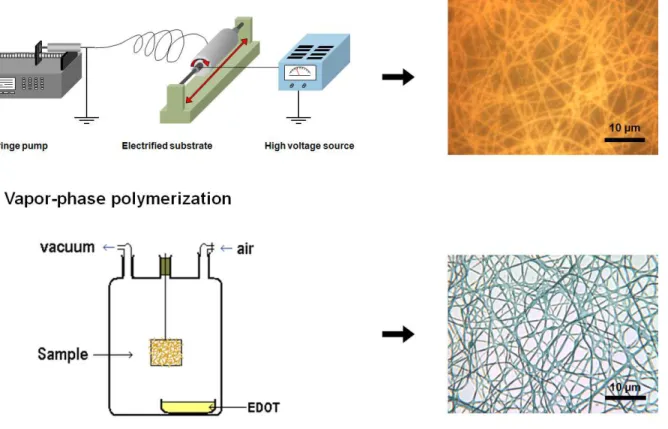
Electrospinning. The PVP powder was dissolved into the CB40 solution together with a small amount of pyridine (0.5 mol/mol FeTos), by magnetically stirring overnight in a closed vial at 50 ºC. The polymer solution was then filled into a glass syringe terminated by a stainless steel needle (n°20: φext = 0.91 mm; φint = 0.58 mm). The syringe was placed in an automatic pump (Harvard Apparatus
PHD4400) and grounded (cf. Figure. 1). A stainless steel substrate covered with a woven textile was connected to a high voltage power supply (Gamma High Voltage Research Model ES75P-10W). The woven textile was used as a non-adhesive substrate, in order to easily remove the nanofiber mat. The distance between the needle and the substrate was fixed at 15 cm and the voltage at 27 ± 1 kV. Relative humidity (RH) in the electrospinning chamber was set to 10 ± 2 % in order to prevent the nanofibers to liquefy by humidity uptake. The temperature was 30 ± 5 ºC. The electrospinning process was very stable and could typically run for hours.
Vapor-phase polymerization. After electrospinning, the non-woven mats were immediately placed in a glass reactor before taking them out of the electrospinning chamber, in order to avoid any contact of the mats with the ambient humidity. The reactor was placed under active vacuum for 15 s and then closed under passive vacuum for the desired polymerization time. The monomer vapors, placed in a small vial containing the liquid EDOT at the bottom of the reactor, progressively filled the reactor (cf. Figure 1). After polymerization, the mats were removed from the reactor and let in ambient atmosphere for 3 to 4 hours, to ensure complete evaporation of the EDOT vapors. They were then soaked in methanol for 30 min and dried under vacuum at room temperature for 2 hours.
Characterization. Scanning electron microscopy (SEM) was performed on a Hitachi S4700 microscope, and transmission electron microscopy (TEM) on a Philips CM200 microscope at 200 kV. X-Ray diffraction patterns were acquired using a Bruker AXS D8 Discover diffractometer with a Cu Kα radiation source (λ = 1.54 Å). FTIR spectra were recorded in the attenuated total reflexion (ATR) mode with a Nicolet Magna-IR 860 spectrophotometer, using the Thunder Dome or Golden Gate techniques. UV-Vis-NIR spectroscopy was performed on a Perkin Elmer Lambda 950.
Four-point probes conductivity measurements were carried out using a home made device consisting on four parallel platinum wires positioned 0.2 cm away from each other, connected to a VMP3 multipotentiostat (BioLogic, Inc.). A range of current intensities were applied to the two external probes and the corresponding voltage drops between the two internal probes were measured. Electrochemical characterization was performed with a VMP3 multipotentiostat using a three-electrode conFigureuration. The electrospun mat was connected using a simple alligator clip. The reference and counter electrodes were an Ag/AgCl, NaCl saturated electrode and a platinum grid, respectively. The electrolyte was NBu4PF6 0.1 M in acetonitrile. Electrochemistry was performed in a closed home-made
electrochemical cell in ambient conditions.
Results and Discussion
Fabrication of PEDOT nanofibers. The commercially available FeTos solution has a high viscosity (0.025 Pa.s) as well as a significant electrical conductivity (salt content: 40 wt%, σ = 0.52 mS/cm), two key properties to achieve electrospinning at low polymer content. As expected, the solution was not electrospinnable by itself, leading to electrospraying and the deposition of droplets. In previous work, very small amounts of a high molecular weight polyethylene oxide (PEO, 1,000,000 g/mol) were added to the solution.36However, the viscosity of the solution became so high after the addition of only 1 wt% of PEO that a gel formed at room temperature. Therefore, the electrospinning process required the use of a heatgun to liquefy the solution and help blowing the fibers towards the substrate. Nanofibers were
successfully obtained, but the reproducibility of the process was limited due to the difficulty in controlling very specific parameters of the heating/blowing process such as distance, angle, temperature and air flow from the heatgun. In the present work, the gelification of the oxidant solution was avoided by using a high molecular weight polyvinylpyrrolidone (PVP, 1,300,000 g.mol-1), a polymer more soluble in butanol, the solvent of the oxidant solution, than PEO. Small amounts of pyridine were also added to the FeTos solution as a base inhibitor in order to hinder acidic side-reactions during the subsequent polymerization.23 The viscosity of the FeTos+PVP solution was monitored as a function of PVP content (cf. Figure S1). An exponential growth of the viscosity was observed, with an increase of almost one order of magnitude at only 1 wt% PVP (0.17 Pa.s). While the electrospinning of the 1 wt% and 1.5 wt% PVP solutions was successful, solutions with concentrations above 2 wt% were too viscous to obtain stable electrospinning conditions. For the following experiments, the PVP concentration was fixed at 1 wt%. Figure 1 shows the typical two-step procedure for the fabrication of PEDOT nanofibers, as well as optical micrographs of the corresponding nanofibers. The oxidant nanofibers presented the yellow-orange color typical of FeTos. After evaporation of the solvent during the electrospinning process, the formulation of the nanofibers was 91.3 wt% of FeTos, 6.4 wt% of pyridine and 2.3 wt% of PVP. As mentioned above, these fibers had a very low polymer content, which should minimize the reduction of the electroactive properties due to blending. However, due to this low polymer content, the FeTos nanofibers were extremely sensitive to humidity and liquefied within a few hours by incorporation of water, if not kept in a very dry environment (relative humidity < 15%). Figure S2 shows the fibers before and after 1 min spent in ambient conditions (24 ºC, 53 % relative humidity). To maintain the oxidant nanofiber integrity while being produced, the electrospinning was performed in a controlled chamber kept at 10 % of relative humidity.
Figure 1. Scheme of the two-step nanofiber production. On the right-side are optical micrographs of the resulting nanofibers (reflection mode for step 1 and transmission mode for step 2).
After their production, the FeTos nanofibers were directly transferred into the VPP reactor avoiding the contact with a humid atmosphere. In the first experiments, the conventional VPP procedure was followed, meaning that the reactor was filled with a dry argon gas, a small vessel containing the liquid EDOT monomer being placed at the bottom of the reactor and maintained at a controlled temperature (typically 50 ºC).23 Argon was bubbled through the liquid monomer to carry more efficiently the monomer vapors into the reactor. However, this procedure led to a competition between the liquefying of the oxidant nanofibers as the monomer vapors were absorbed on their surface, and the EDOT polymerization. Depending on the process parameters, the resulting structures varied from totally melted PEDOT thin films to a blend of fused fibers and thin films (cf. Figure S3). It was not possible to obtain neat fibers by varying the electrospinning parameters (temperature, argon flow, distance from monomer vessel to the fibers, etc…). The procedure was then modified by placing the reactor under passive
vacuum, at ambient temperature, instead of placing it under argon atmosphere at 50 ºC (cf. Figure. 1). Vacuum as well as ambient temperature were chosen to slow down the vapor absorption process and favor the polymerization reaction. Active vacuum was not used because of a progressive evaporation of the pyridine contained in the fibers that led to acidic side-reactions during the polymerization. An optical micrograph of the nanofibers obtained using the vacuum-VPP procedure is shown in Figure 1. The oxidant nanofibers did not liquefy during the VPP process and the final nanofibers displayed the light blue color characteristic of doped PEDOT. Following the VPP polymerization, the fibers stayed in air for a few hours, in order to remove any excess of EDOT vapors, and then rinsed using methanol to remove unreacted oxidant, reduced iron species as well as the PVP present in the fibers.
Morphological analysis. The final rinsing step was found to lead to a radical transformation of the fiber geometry. It was found that longer polymerization times were required if the VPP process was carried out under vacuum than under argon, probably because of the lower EDOT vapor pressure in the reactor. A reaction time of at least 120 hours appeared to be necessary to reach sufficient EDOT polymerization under vacuum and ambient temperature. Lower reaction times caused the fibers to partially dissolve during the rinsing step due to a large excess of unreacted oxidant species (cf. Figure. S4).
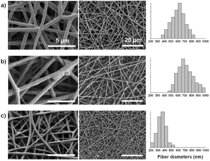
The average fiber diameter was drastically reduced during the rinsing step. Figure 2 shows SEM images of the nanofibers and corresponding fiber diameter distributions after the three main production steps: after electrospinning, after polymerization and after rinsing. The average diameter of the electrospun FeTos fibers was 600 ± 100 nm. After polymerization, the average diameter increased to 710 ± 110 nm. However, after rinsing with methanol, the average diameter of the fibers decreased to 350 ± 60 nm.
Figure 2. SEM images at different magnifications and corresponding diameter histograms of the nanofibers at each fabrication step: (a) after electrospinning, (b) after EDOT polymerization and (c) after rinsing with methanol.
Both phenomena described in Figure. 2 and Figure. S4 are thought to be related to the slow polymerization kinetics during the vacuum-VPP procedure: at the beginning of the process, the monomer vapors polymerized as a thin layer at the surface of the FeTos fibers until a compact PEDOT layer was formed. This layer then acted as a sheath that limited further diffusion of the EDOT vapors inside the fiber structures. For short reaction times (up to several tens of hours), the PEDOT sheath was too thin to support the rinsing procedure resulting in partially melted structures (Figure S4). For reaction times over 100 h, the PEDOT sheath had grown thicker and was mechanically stronger. However, Figure 2 shows that the surface of the nanofibers is much more textured after the rinsing step. It is
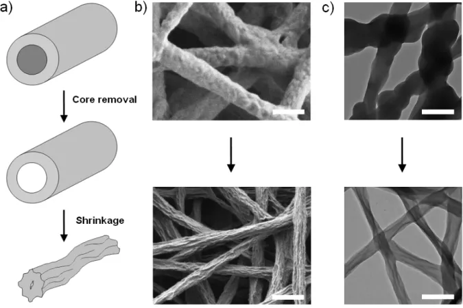
believed that even though the PEDOT top layer was thick enough to maintain its mechanical integrity during rinsing, the fiber structures probably collapsed and shrunk when the core of the fiber (containing mostly soluble unreacted oxidant) was removed. The phenomenon is schematically illustrated in Figure 3. This assumption is supported by SEM and TEM observations: the surface of the unrinsed fibers presented a rough nodular morphology (Figure. 3b, top). A clear core-sheath morphology was difficult to observe by TEM (cf. Fig. 3c, top) and we believe that the main reason is that the front of polymerization was not clearly defined in the fiber (the scheme in Fig. 3a is simplified for a better understanding). After rinsing, the surface morphology was drastically changed, together with the decrease in average fiber diameter. Surface and bulk features of typical shrunk structures could be observed by SEM and TEM (Figs. 3b and 3c, bottom).
Figure 3. (a) Schematic representation of the proposed nanofibers shrinkage process upon rinsing with methanol. (b) SEM and (c) TEM images of the nanofibers before and after rinsing. All scale bars represent 1 µm.
A comparable shrinkage process has also been observed during the electrospinning of polycarbonate nanofibers where the solvent evaporation at the surface of the polymer caused a wet-core/dry-sheath structure to be produced.37 The sheath density was observed to be higher than the core density, and the subsequent evaporation of the solvent in the core caused the sheath to collapse, resulting in a global shrinkage of the fibers, which resulted in surface morphologies similar to the observations of the present study.
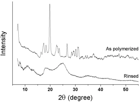
Structural analysis. A structural analysis was performed using X-ray diffraction. As can be seen on Figure 4, the X-ray patterns are radically different before and after rinsing. Multiple well-defined peaks are present in the as-polymerized nanofibers. These peaks correspond to the FeTos salt, confirming that a significant part of the oxidant has not been consumed by the EDOT polymerization. After rinsing, the peaks related to the tosylate ion disappeared and were replaced by new peaks at 2θ = 11.0º, 13.3º, 18.5º and 25.0º . In similar XRD studies, these new peaks have been attributed to the crystalline lattice of PEDOT chains doped by tosylate anions.38, 39 The crystalline structure is orthorhombic, the peaks at scattering angles 2θ = 11.0º, 13.3º, 18.5º and 25.0º being assigned to the [200], [300], [400] and [020] reflections respectively. The average crystalline cell has lattice parameters a = 14.0-14.3 Å, b 7.2 = Å, and c = 8.0 Å, c representing the monomer spacing, b/2 (3.6 Å), the interchain π-π stacking distance and a, the inter-chain distance between stacked chains.38, 39 The crystallinity of the PEDOT was not quantitatively measurable because no clear amorphous halo was detected (cf. Fig. 4). However, it can be concluded from the XRD patterns that the PEDOT chains are highly ordered by π-π interactions, this crystallinity being obtained from the templating effect of the tosylate ion, giving that the VPP is a solvent-free process.40
Figure 4. X-ray diffraction patterns of the nanofibers as polymerized (t =120 h) and after rinsing with methanol.
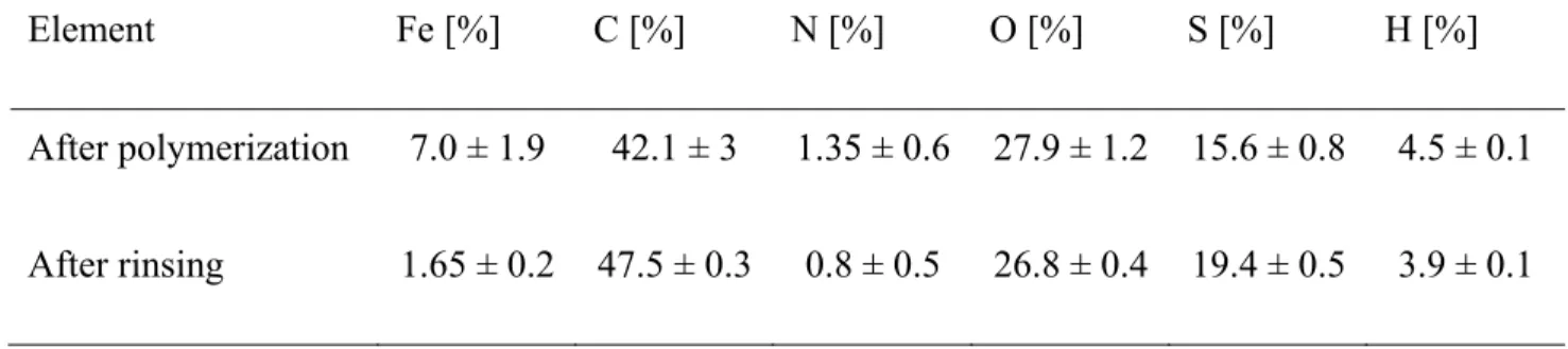
Elemental analysis was performed to obtain additional information on the rinsing effect (cf. Table 1). The results were difficult to analyze because of the complexity of the system and the unknown ratios between the different components in the final structures (doped PEDOT, oxidant and PVP). To improve our confidence in the results, three samples of each composition were tested and the results presented in Table 1 represent the average of the three analysis. It can be noted that the uncertainty on the results is more important on the samples before rinsing. Indeed, the unreacted core-layer’s thickness can vary from sample to sample, inducing a slight discrepancy in the elemental composition. However, after rinsing with methanol, the standard deviation was reduced to that of conventional imprecision for elemental analysis (i.e. 0.1 to 0.5 %, depending on the element), which was expected since the unreacted species were removed from the sample at the rinsing step. It is clear from this data that a significant amount of oxidant was removed after rinsing (Fe decreased from 7 to 1.65 %). The remaining iron content was typical of ICPs polymerized using iron salts.41 Another important information was the presence of nitrogen (attributed to PVP) after rinsing, even if decreased. This data suggests that part of
the PVP remained in the final fiber structures after the rinsing procedure despite its solubility in methanol. This could be explained by the formation of an interpenetrating network during the in-situ polymerization of PEDOT in the PVP/oxidant fibers, which would hinder the dissolution of PVP.
Table 1. Elemental analysis of the nanofibers after polymerization and after rinsing with methanol. Element Fe [%] C [%] N [%] O [%] S [%] H [%] After polymerization 7.0 ± 1.9 42.1 ± 3 1.35 ± 0.6 27.9 ± 1.2 15.6 ± 0.8 4.5 ± 0.1 After rinsing 1.65 ± 0.2 47.5 ± 0.3 0.8 ± 0.5 26.8 ± 0.4 19.4 ± 0.5 3.9 ± 0.1
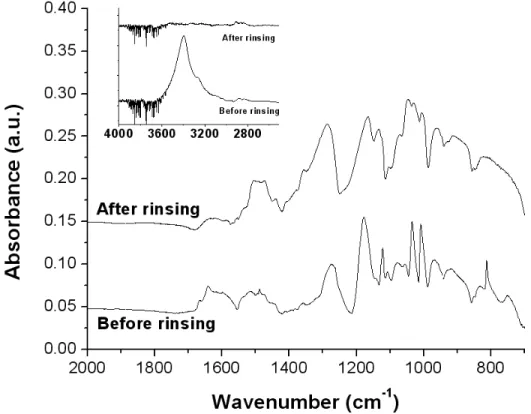
Spectroscopic properties. Figure 5 presents the FTIR spectrum of PEDOT nanofibers before and after rinsing. The spectra display significant differences : disappearance or strong decrease of FeTos-associated bands (812, 1008, 1034 and 3400 cm-1, cf. Figure S5) as well as decrease of a band associated with PVP at 1630 cm-1. The presence of this latter peak even after rinsing confirms that even if an important part of the PVP is removed by the rinsing procedure, some PVP stays trapped into the nanofibers, as already evidenced by the elemental analysis (cf. Table 1). The spectrum of the final product (after rinsing) is typical of oxidized PEDOT (p-doped by tosylate anions).42 The C=C stretching peak associated with the quinoid form of the doped polymer backbone can be observed at 1506 cm-1.
42-45
The absence of carbonyl peaks around 1700-1730 cm-1 demonstrates that no damage to the monomer units occurred due to acidic side-reactions during the polymerization, as observed by several teams.23, 24,
Figure 5. FTIR spectrum of the PEDOT nanofibers before and after methanol rinsing. Inset represents the 2500-4000 cm-1 area.
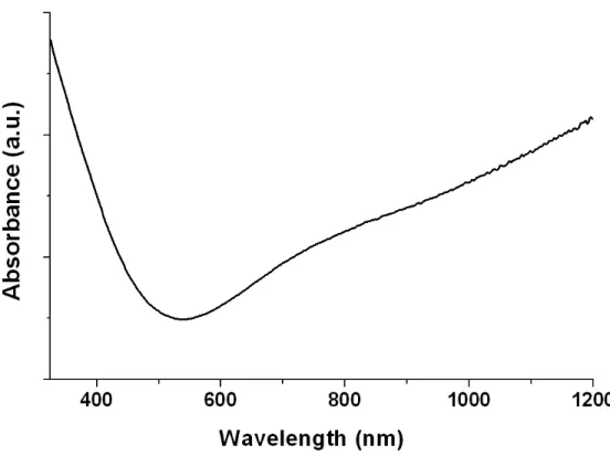
The UV-Vis-NIR spectrum was performed on the rinsed PEDOT nanofibers deposited on a PET (polyethylene terephthalate) sheet (transparent above 310 nm) (cf. Figure 6). The characteristic PEDOT spectrum can be observed, with a low absorption in the visible and an increased absorption after 700 nm, extending in the NIR region, which has been reported as a strong bipolaron absorption, indicating high level of doping.44, 47 It is important to note that an increase of absorption was also observed below 500 nm which is unusual in PEDOT spectra. However, this phenomenon has already been observed on PEDOT thin films and was attributed to the presence of an important concentration of oligomers, leading to poorly conducting polymers.44According to this report, the oligomers were also detected by the presence of a peak at 3110 cm-1, attributed to the C-H elongation vibration of the carbons in alpha position from the sulfur atom of the EDOT monomer.44, 46 However, no such peak was detected in the spectrum of the PEDOT nanofibers fabricated in this study, as can be observed in the inset of Figure 5.
Based on these experiments, we cannot state that the increase of absorbance below 500 nm in the UV-Vis spectrum was related to the presence of oligomers in the polymer. Other experiments are being currently undertaken to better understand the origin of the phenomenon.
Figure 6. UV-Vis-NIR spectrum of the rinsed PEDOT nanofibers.
Electrical and electrochemical properties. The electrical conductivity of the nanofibrous mats was measured with a 4-points probe device (cf. Experimental Section). The average conductivity was 60 ± 10 S/cm. To our knowledge, this is the highest conductivity value ever reported for electrospun polymer nanofibers. Other PEDOT-containing nanofibers have been reported with conductivities from 10-4 to 1 S/cm, depending on the method of PEDOT incorporation into the nanofibers.48-51 The high conductivity measured in this study is believed to result from the crystalline nature of the PEDOT obtained by the combination of the VPP process and the use of FeTos as the oxidant. Moreover, we observed a soldering phenomenon at fiber intersections after polymerization (cf. Figure S6). This suggests that the
fibers are bonded to one another at multiple junctions, ensuring a good contact between the fibers and therefore a low ohmic barrier to the charge transport from one fiber to another. This soldering effect also provides a strong dimensional stability to the mat compared to conventional electrospun mats.
It is important to point out that the conductivity values obtained using the four-point probe technique are volume conductivities, that do not take into account the materials porosity.21 The porosity of the fiber mats prepared in this study was estimated to be 80 ± 5 % by simple weighting experiment, using a density of 1.6 g.cm-3 for tosylate-doped PEDOT.52 By taking into account that the PEDOT nanofibers themselves represent only ~ 20 % of the sample volume, it can be estimated that individual fibers should have conductivities around 300 S/cm.
To compare this value with non-porous materials, several PEDOT thin films were vapor-phase polymerized with the same protocol, using spin-coated FeTos and FeTos-PVP thin films. However, a necessary annealing step (70 °C, 5 min) was added before the polymerization, in order to evaporate the solvent. In the electrospinning process, the solvent is evaporated during the flight of the fiber between the needle and the substrate. The conductivity average value for the thin films was 520 ± 40 S/cm, the addition of PVP having no detrimental effect on the conductivity. This value is in the same order of magnitude than the one estimated for the single fibers (~ 300 S/cm). The difference could be explained by a non-perfect electrical interconnectivity between the fibers, even though they are soldered at a number of junctions, which would lower the estimated value of the single fibers conductivity.
The electrochemical properties of the nanofiber mats were investigated using cyclic voltammetry in an organic medium (NBu4PF6 0.1M in acetonitrile). No specific precautions were taken in order to
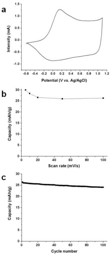
prevent pollution of the medium by oxygen and water. The mats were connected at one extremity by an alligator clip, without the use of any additional current collector. Figure 7a displays a cyclic voltammogram, showing the typical doping/undoping process of PEDOT with an oxidation peak at 0.15 V vs. Ag/AgCl and a reduction peak at 0 V vs. Ag/AgCl. The peaks are very well defined, confirming the high conductivity of the material. The coulombic reversibility of the doping/undoping process was
above 99 %, showing the highly efficient insertion/desinsertion of the doping anions during the electrochemical process. In order to further evaluate this efficiency, cycling at more elevated scan rates was performed and the results are shown in Figure 7b. After a slight capacity decrease (30 to 26 mAh/g) caused by an increase of the scan rate from 5 to 20 mV/s, no further decline was observed at scan rates up to 100 mV/s. The steadiness of the storage capacity at high scan rates demonstrates that ions are capable of inserting/desinserting from the electrolyte at high speed, most probably due to the very high porosity of the active materials (~ 80%).
The charge/discharge cyclability was tested at a scan rate of 50 mV/s. The electrode capacity stability over 100 cycles is presented in Figure 7c. A slight and constant decrease can be observed on the graphic. Given that the cycling experiment was performed in ambient conditions in a one-compartment cell, with the counter-electrode close to the working electrode, this slight decrease is believed to be due to the continuous degradation of the electrolyte upon oxidation/reduction reactions at the counter-electrode, rather than PEDOT degradation. Indeed, the electrolyte turned from perfectly transparent to slightly yellow during the experiment. Tests in more stable and inert atmosphere conditions will be part of future investigations.
Figure 7. Electrochemical properties of the PEDOT nanofiber mats in an organic electrolyte (NBu4PF6
0.1M in acetonitrile) ; a) cyclic voltammogram at 5 mV/s ; b) electrode capacity as a function of the scan rate ; c) electrode capacity during cycling at 50 mV/s. mPEDOT = 2.0 mg.
Conclusion
A two-step procedure combining electrospinning and vapor-phase polymerization was developed in order to obtain highly conductive PEDOT nanofibers. The first step involved the electrospinning of an oxidant solution containing a small amount of carrier polymer. In the second step, the EDOT monomer was polymerized on top of the oxidant nanofibers using a vapor-phase deposition procedure. The polymerization was to done under vacuum in order to prevent partial melting of the nanofibers, due to an excessive incorporation of the monomer vapors. The resulting PEDOT nanofibers were rinsed with methanol in order to remove the excess reactants and co-products. The fibers displayed diameters around 350 ± 60 nm and showed a crystalline structure, typical of vapor-phase polymerized PEDOT. The conductivity of the mats was measured around 60 ± 10 S/cm, which is, to our knowledge, the highest value ever reported for polymeric nanofibers. The nanofibers also demonstrated improved electrochemical properties upon cycling, most likely due to the ultraporous nature of the mats (~ 80%). These nanofibers developed in this work could find applications in the development of flexible electronics such as sensors, as well as active materials for energy storage devices.
Acknowledgements. The authors would like to thank Karine Théberge from NRC-IMI for the SEM, TEM and XRD experiments as well as Nicole Côté for the FTIR analysis.
Supporting Information Available: viscosity study, optical and SEM micrographs of nanofibers mats under different processing conditions, FTIR spectra of the FeTos solution as well as butanol and FeTos salt.
References
(1) Bhattacharya, A.; De, A. JMS - Rev. Macromol. Chem. Phys. 1999, C39 (1), 17-56. (2) Choi, D.; Song, K.; Lee, J. Y. Mol. Cryst. Liq. Cryst. 2002, 377, 365-368.
(3) Pan, W.; Yang, S.; Li, G.; Jiang, J. Int. J. Polym. Mater. 2005, 54, 21-35. (4) Zilberman, M.; Siegmann, A.; Narkis, M. Polym. Adv.Tech. 2000, 11, 20-26. (5) McCullough, R. D. Adv. Mater. 1998, 10, (2), 93-116.
(6) Wang, X.; Drew, C.; Lee, S.-H.; Senecal, K. J.; Kumar, J.; Samuelson, L. A. J. Macromol. Sci. Pure
Appl. Chem. 2002, A39, (10), 1251-2158.
(7) Senesac, L.; Thundat, T. G. Materials Today 2008, 11, (3), 28-36.
(8) Cho, S. I.; Kwon, W. J.; Choi, S.-J.; Kim, P.; Park, S.-A.; Kim, J.; Son, S. J.; Kim, S.-H.; Lee, S. B.
Adv. Mater. 2005, 17, (2), 171-175.
(9) Nyström, G.; Razaq, A.; Strømme, M.; Nyholm, L.; Mihranyan, A. Nano Letters 2009, 9, (10), 3635-3639.
(10) Simon, P.; Gogotsi, Y. Nature Materials 2008, 7, 845-854.
(11) Wallace, G. G.; Chen, J.; Mozer, A. J.; Forsyth, M.; MacFarlane, D. R.; Wang, C. Materials Today
2009, 12, (6), 20-27.
(12) Liu, R.; Cho, S. I.; Lee, S. B. Nanotech. 2008, 19, 215710.
(13) Greiner, A.; Wendorff, J. H. Angew.Chem. Int. Ed. 2007, 46, 5670-5703.
(14) Ramakrishna, S.; Fujihara, K.; Teo, W.-E.; Yong, T.; Ma, Z.; Ramaseshan, R. Materials Today
2006, 9, (3), 40-50.
(15) Li, M.; Guo, Y.; Wei, Y.; MacDiarmid, A. G.; Lelkes, P. I. Biomaterials 2006, 27, 2705-2715. (16) MacDiarmid, A. G.; Jones, W. E.; Norris, I. D.; Gao, J.; A. T. Johnson, J.; Pinto, N. J.; Hone, J.; Han, B.; Ko, F. K.; Okuzaki, H.; Llaguno, M. Synth. Met. 2001, 119, 27-30.
(17) Ju, Y.-W.; Park, J.-H.; Jung, H.-R.; Lee, W.-J. Electrochimica Acta 2007, 52, 4841-4847. (18) Chronakis, I. S.; Grapenson, S.; Jakob, A. Polymer 2006, 47, 1597-1603.
(19) Chuangchote, S.; Srikhirin, T.; Supaphol, P. Macromol. Rapid Commun. 2007, 28, 651-659.
(20) Xin, Y.; Huang, Z. H.; Yan, E. Y.; Zhang, W.; Zhao, Q. Appl. Phys. Lett. 2006, 89, 053101-1 - 053101-3.
(21) Laforgue, A.; Robitaille, L. Synth. Met. 2008, 158, 577-584.
(22) Lee, S.; Moon, G. D.; Jeong, U. J. Mater. Chem. 2009, 19, 743-748. (23) Winther-Jensen, B.; West, K. Macromolecules 2004, 37, 4538-4543.
(24) Lock, J. P.; Im, S. G.; Gleason, K. K. Macromolecules 2006, 39, 5326-5329.
(25) Winther-Jensen, B.; Forsyth, M.; West, K.; Andreasen, J. W.; Bayley, P.; Pas, S.; MacFarlane, D. R. Polymer 2008, 49, 481-487.
(26) Street, R. A. Nature Materials 2006, 5, 171-172.
(27) Subramanian, P.; Clark, N. B.; Spiccia, L.; MacFarlane, D. R.; Winther-Jensen, B.; Forsyth, C.
Synth. Met. 2008, 158, 704-711.
(28) Levermore, P. A.; Chen, L.; Wang, X.; Das, R.; Bradley, D. D. C. Adv. Mater. 2007, 19, 2379-2385.
(29) Admassie, S.; Zhang, F.; Manoj, A. G.; Svensson, M.; Andersson, M. R.; Inganäs, O. Sol. Ener.
Mat. Sol. Cells 2006, 90, 133-141.
(30) Winther-Jensen, B.; Krebs, F. C. Sol. Ener. Mat. Sol. Cells 2006, 90, 123-132. (31) Nair, S.; Natarajan, S.; Kim, S. H. Macromol. Rapid Commun. 2005, 26, 1599-1603.
(32) Granato, F.; Bianco, A.; Bertarelli, C.; Zerbi, G. Macromol. Rapid Commun. 2009, 30, 453-458. (33) Wang, H.; Ding, J.; Lee, B.; Wang, X.; Lin, T. J. Membr. Sci. 2007, 303, 119-125.
(34) Bai, H.; Zhao, L.; Lu, C.; Li, C.; Shi, G. Polymer 2009, 50, 3292–3301.
(35) Bolin, M. H.; Svennersten, K.; Wang, X.; Chronakis, I. S.; Richter-Dahlfors, A.; Jager, E. H.; Berggren, M. Sens. Actuat. B 2009, 142, 451–456.
(36) Laforgue, A.; Robitaille, L. Polym. Preprints 2008, 49, (2), 624-625.
(38) Aasmundtveit, K. E.; Samuleson, E. J.; Inganäs, O.; Petterson, L. A. A.; Johansson, T.;Ferrer, S.
Synth. Met. 2000, 113, 93-97.
(39) Kim, T. Y.; Park, C. M.; Kim, J. E.; Suh, K. S. Synth. Met. 2005, 149, 169-174.
(40) Winther-Jensen, B.; Forsyth, M.; West, K.; Andreasen, J. W.; Wallace, G.; MacFarlane, D. R. Org.
Elec. 2007, 8, 796-800.
(41) Abdou, M. S. A.; Lu, X.; Xie, Z. W.; Orfino, F., Deen, M. J.; Holdcroft, S. Chem. Mater. 1995, 7, 631-641.
(42) Kvarnström, C.; Neugebauer, H.; Ivaska, A.; Sariciftci, N. S. J. Mol. Struct. 2000, 521, 271-277. (43) Neugebauer, H. J. Electroanal. Chem. 2004, 563, 153–159.
(44) Fabretto, M.; Zuber, K.; Murphy, C. H. Macromol. Rapid Communi. 2008, 29, 1403-1409. (45) Im, S. G.; Gleason, K. K. Macromolecules 2007, 40, 6552-6556.
(46) Kim, S.; Pang, I.; Lee, J. Macromol.Rapid Commun. 2007, 28, 1574-1580.
(47) Pei, Q.; Zuccarello, G.; Ahlskog, M.; Inganäs, O. Polymer 1994, 35, (7), 1347-1351. (48) El-Aufy, A. K.; Naber, B.; Ko, F. K. Polym. Preprints 2003, 44, (2), 134-135. (49) Panapoy, M.; Saengsil, N.; Ksapabutr, B. Adv. Mater. Res. 2008, 55-57, 257-260. (50) Nair, S.; Hsiao, E.; Kim, S. H. Chem. Mater. 2009, 21, 115-121.
(51) Nguyen, H. D.; Ko, J. M.; Kim, H. J.; Kim, S. K.; Cho, S. H.; Nam, J. D.; Lee, J. Y. J. Nanosci.
Nanotech. 2008, 8, 4718-4721.
(52) Aasmundtveit, K. E.; Samuelsen, E. J.; Pettersson, L. A. A.; Inganas, O.; Johansson, T.; Feidenhansl, R. Synth. Met. 1999, 101, 561-564.
TOC Graphic.
Production of conductive PEDOT nanofibers by the combination of electrospinning and vapor-phase polymerization