HAL Id: hal-00599772
https://hal.archives-ouvertes.fr/hal-00599772
Submitted on 11 Jun 2011HAL is a multi-disciplinary open access archive for the deposit and dissemination of sci-entific research documents, whether they are pub-lished or not. The documents may come from teaching and research institutions in France or abroad, or from public or private research centers.
L’archive ouverte pluridisciplinaire HAL, est destinée au dépôt et à la diffusion de documents scientifiques de niveau recherche, publiés ou non, émanant des établissements d’enseignement et de recherche français ou étrangers, des laboratoires publics ou privés.
TEM characterization of the fine scale microstructure of
a Roman ferrous nail
Joël Douin, O. Henry, F. Dabosi, Philippe Sciau
To cite this version:
Joël Douin, O. Henry, F. Dabosi, Philippe Sciau. TEM characterization of the fine scale microstructure of a Roman ferrous nail. European Physical Journal: Applied Physics, EDP Sciences, 2010, 51 (1), �10.1051/epjap/2010074�. �hal-00599772�
TEM characterization of the fine scale microstructure of
a Roman ferrous nail
J. Douin
a,b, O. Henry
a,b, F. Dabosi
c,d, Ph. Sciau
a,ba CNRS; CEMES; BP 94347, 29 rue J. Marvig, F-31055 Toulouse, France b Université de Toulouse; UPS, INSA; CEMES; F-31055 Toulouse, France
c CIRIMAT, ENSIACET, INPT, 4 allée Emile Monso, BP 74233, F-31432 Toulouse Cedex 4, France d TRACES, UMR 5608, Université de Toulouse-Le Mirail, F-31058 Toulouse, France
ABSTRACT
This paper describes the microstructure of a Roman ferrous nail through its observation by transmission electron microscopy. The morphologies of pearlitic colonies and ferritic grains are detailed and the relationship between pearlitic colonies and ferrite in Roman nails is explicitly demonstrated for the first time. Observations also confirm the presence of dislocations in ferritic grains and attest to the existence of very small carbide precipitates that have not been pointed out previously in standard archaeometric studies.
Keywords: Iron; Microstructure; Transmission Electron Microscopy; Archaeometallurgy; Roman period,
1 Introduction
Iron is one of the materials that has most contributed to the economical, sociological and scientific evolution of humankind. Pure iron is not a hard material and iron metallurgy only became critical when techniques to improve its mechanical properties were discovered. Steel gets most of its attractive mechanical properties from adequate alloying of iron with carbon, but also from the controlled conditions of the elaboration process, leading to large changes in the fine microstructure, thus the mechanical properties. For a long time, iron was not produced by the same procedure as modern steel, which undergoes complex but well documented processes. Little is known on the sub-micronic microstructure of ancient irons. In Western Europe, from the Iron Age to the production process using a form of cast iron, also called pig iron, i.e. a time span of about 2500 years, there has been little change in the basic operation of iron manufacturing by direct reduction of iron ores [1-5].
Nails are par excellence common artefacts of the Roman period. Roman nails have been previously studied by many authors (see for example [6-9]). Studies have shown that, at that time, iron production and processing used to produce nails had become pre-industrial and were already playing a significant part of the economic and military development. The so-called bloomery process, also referred to as “direct reduction”, was the original method of producing iron. It operates on a small scale with charcoal and at relatively low temperatures, firstly in bowl and then in schaft furnaces, giving a spongious loop of more or less malleable iron due to its carbon content polluted by slags and residual charcoal pieces. The reduction reactions are complex in the wide range of temperatures and atmospheres encountered in the shaft furnace, with for the former a maximum value of 1250-1300°C, much lower than the melting point of iron (1532°C). So, the reduction occurs in solid state with separation of a pasty metallic sponge. The slags, issued from the gangue minerals (silicates, alumina and lime), with a melting point around 1200°C, are liquid and usually eliminated by pouring them out of the furnace through a hole in the bottom part of its wall. Then, the iron loop is refined in a refinery forge: the blacksmith has to remove the slag and charcoal inclusions from the metallic mass through repetitive hammering and reheating in order to make the carbon steel more homogeneous and malleable. Then the metal is usually hot-worked by forging wrought bars that can be reshaped into various implements. It must be just mentioned here that, later in Europe, around the 14th and 15th centuries A.D., much higher temperatures of 1700°C or more
were reached with the blast furnace. The associated process, called indirect reduction, involves the initial production of liquid cast iron, very brittle after solidification, with 3 to 5%wt of carbon that must be properly decarburized for producing steel or iron.
To our knowledge, all the investigations on such archeological irons were done on a scale where very fine details of the microstructure are not observable, at most using scanning electron microscopy (SEM). For example, the observation of dislocations or nanometric carbide precipitates, which play a major role in mechanical properties, requires a better resolution. Moreover, because there is a strong heterogeneity in the carbon content of iron crystallites only, it is the purpose of this paper to explore and discuss the new information on ancient nails obtained by transmission electron microscopy (TEM), at a sub-micronic scale, as it has already been carried out successfully in another field of cultural heritage materials [10].
2 Experimental
We have worked on iron nails (Fig.1) extracted during excavations at Puy d’Issolud (France) where the Uxellodunum battle took place in 52 BC, during the Gallic Wars [11, 12].
Fig. 1. Nails from the Uxellodunum site from which the PM98 steel samples have been selected (Photo courtesy of G. Renoux and F. Dabosi)
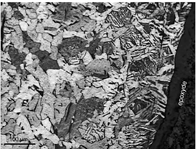
These nails were subject to standard archaeometry studies [12]. Figure 2 shows an optical micrograph after chemical etching to reveal the variation of the grains structure from the surface to the inside of the nails. Near the surface, we observe the typical Widmanstätten structure. On the middle of the micrograph, pearlitic colonies are observed. The inner part of the nail seems essentially constituted by ferritic grains separated by carbides that have precipitated at the grains boundaries. TEM samples were extracted from the inner parts of the nails.
In order to reduce magnetization of the material in the TEM, small squared samples of about 1 mm and 220 µm thick were sliced from the nails, referred here as PM98, and subsequently mechanically ground to a thickness of 25 ± 5 µm. The samples were then electropolished with a Struers A2 electrolyte at -13°C in a Tenupol III apparatus. The thin foils were then examined using a JEOL 200 CX electron microscope operating at 200 kV equipped with a double tilt goniometer stage.
Fig. 2. Optical micrograph of the PM98 nail. On the left, inner part of the nails with ferritic grains and carbides precipitated at the grains boundaries; in the center, pearlitic colonies; near the surface, Widmanstätten structure. The dark layer on the right part of the micrograph is the epoxyde used for sample preparation.
3. Results and Discussion
3.1 General microstructure
Figure 3 shows general views of the microstructure of the inner part of PM98 Roman nail by TEM.
From the optical micrographs (fig. 2) it was assumed that the microstructure was essentially formed by ferritic grains, TEM reveals that it is formed by a mixture of grains of ferrite (α) and colonies of pearlite, the latter being a lamellar mixture of ferrite and of the
cementite iron carbide Fe3C. The microstructure is not very homogeneous as the relative
density of pearlitic and ferritic areas varies in the different observed thin foils obtained from different parts of the nails.
When slowly cooled down, alloys containing less than 0.8 wt% carbon, formed hypo-eutectoid ferrite from austenite, in the range 910°C-723°C with enrichment of the residual austenite in carbon, until at 723°C the remaining austenite, now containing 0.8% wt carbon transforms to pearlite (for a comprehensive review, see [13]). The three components - ferrite, cementite and pearlite - are then the principal constituents of the microstructure of plain carbon steels, provided they have been subjected to relatively slow cooling rates to avoid the formation of metastable phases, i.e. martensite or bainite. No metastable phase has been evidenced during our observations, which attests that the thermodynamical equilibrium has been reached during the production process.
Fig. 3. TEM observation of the microstructure of the PM98 nail showing intricate pearlitic colonies (P) and ferritic areas (F) (limits are underlined).
3.2 Pearlitic colonies
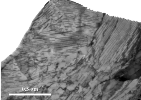
Some areas of the microstructure are dominated by pearlitic colonies (Figure 4). The orientation of the cementite lamellae are usually related to the orientation of an adjacent
austenite grain [13], thus present various different orientations depending of the neighboring grain.
When observed with a higher magnification, the cementite laths appear very well organized within a colony, with a constant orientation and separation distance (Figures 4 and 5). This is particularly clear when the laths are seen end-on, an observation that allows to determine the average thickness of the laths: l = 40 ± 3 nm.
Fig. 4. Area of the PM98 nail dominated by pearlitic colonies with various orientations.
Fig. 5. One pearlitic colony showing the arrangement of the parallel cementite laths over a large range scale. Notice the very regular spacing between cementite lamellae.
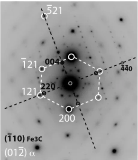
The orientation relationship (OR) between the Fe3C lamellae and the ferritic matrix can be
determined directly by TEM observations. Two different relationships are usually ascribed to exist in pearlite, the Pitsch/Petch [14, 15] and the Bagaryatski [16] relationships, and often side by side in the same steel. Our observations show that only the Pitsch/Petch relationship is present in the PM98 nail. This is exemplified in Figure 6, which presents a colony of cementite laths embedded in a ferritic matrix, with the (001) plane of the cementite laths parallel to the
!
5 21
( )
of the ferrite matrix. According to the Pitsch/Petch relationship [14, 15]: (100)c at 2.6° from ! 13 1[ ]
α (010)c at 2.6° from ! 113 [ ] α (001)c // ! 5 21( )
αWhen observed along the
!
012
[ ]
axis of the ferritic matrix (Fig. 6b), the selected area diffraction pattern of this area presents characteristic features of the Pitsch/Petch relationship: the diffraction pattern from the cementite phase (in black) is characteristic of its!
1 10
(
)
plane, with the 004 spot from cementite perfectly aligned with the!
5 21 spot of ferrite, and the 220
spot of cementite only slightly misaligned from the 121 spot of ferrite. Notice that the spots of the systematic 220 row of the cementite are visible here due to the fact that diffraction of a thin foil in a TEM allows diffracted beams to be observed even when not perfectly perpendicular to the incident beam provided the foil is thin enough [17].
Fig. 6. (a) Micrograph of a pearlitic colony and (b) the corresponding selected area diffraction pattern (inverted contrast): in white the
!
012
( )
α diffraction spots from ferrite, and in dark from!
1 10
(
)
ccementite. According to the Pitsch/Petch relationship, the
!
5 21
( )
plane of ferrite is parallel to the (001)cplane of the cementite phase.
Pitsch/Petch relationship happens when pearlitic nodules nucleate on clean austenite boundaries, while Bagaryatski relationship was found to hold for pearlite nodules nucleated on hyper-eutectoid cementite. It is then predicted that Pitsch/Petch-type colonies predominate as the true eutectoid composition is approached, whereas Bagaryatski-type colonies should prevail at higher carbon levels. According to [13], the interlamellar spacing is inversely related to the temperature of the pearlite formation: the measured mean spacing of 0.17 µm corresponds to a processing temperature of 900 K for an alloy with 0.8% C, i.e. for eutectoid pearlite. This gives an estimate of the temperature at which the transformation occurred during forging.
On the mechanical point of view, the presence of pearlite strengthens the steel. This is directly related to the confinement of the deformation in the ferrite lamellae: since cementite is hardly deformable, cementite laths form obstacles to the movement of the dislocations, constricting their motion in ferrite lamellae. Strength of pearlite is then expected to increase as the interlamellar spacing is decreased, and the interlamellar spacing is inversely proportional to the degree of undercooling. The interlamellar spacing is assumed to be constant for a given alloy and a given transformation temperature. This is valid for plain carbon steel where the average composition of the pearlite is identical to that of the austenite from which it grows. In the case presented in Fig.6, the average distance between the habit planes of the laths is d = 0.17 ± 0.02 µm, which contributes to an increase to the strength of about µ b/d = 2.10-3 µ
(where b is the modulus of the Burgers vectors of activated dislocations, and µ the shear modulus of ferrite).
3.3 Ferritic grains
Due to the absence of cementite laths, dislocations may more freely be created and move in pure ferritic grains. Indeed, ferritic grains are found with a significant density of dislocations usually interacting to each others (Fig.7a) attesting that the material has been deformed during and/or after the processing. The dislocation density ρ ranges from 1012 to 1013 m-2, significantly smaller than the usual dislocations density of 1015-1016 m-2 of modern steels,
which undergo strong deformation (e.g. lamination) during the material processing. This dislocations density contributes through the forest hardening mechanism to an increase of the strength of the ferritic grains of αµbρ1/2, i.e. approximately 4.10-4 µ (with α = 0.5). Notice
also that this moderate dislocation density in the ferritic grains, as well as the absence of strong stress concentrations, pile-ups, walls of dislocations and/or cracks within the observed microstructure, indicate that the ferritic grains will continue to deform upon stress and then still appear as the ductile part of this material.
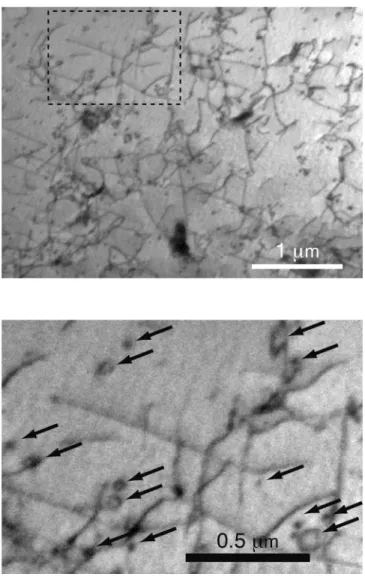
When observed with a higher magnification (Fig. 7b), the frequent occurrence of dislocation loops also attests of the presence of obstacles to the dislocation motion. As the material was slowly cooled down and not quenched, these loops couldn’t have been produced by vacancies condensation. There is an old debate of whether or not the formation of small loops is related to cross-slip in such materials. Cross-slip activity can be observed during deformation of iron. However, in pure iron there is no loop formation (see for example the very recent work by Caillard, [18, 19]), while loops formation is favored by the presence of impurities (see for example in Fe-3%Si [20]). Cross-slip activity is strongly helped by the presence of obstacles, thus the observation of dislocations loops attest to the presence of small areas (that we suppose to be small carbides here) that act as obstacles to the dislocation motion. Such dislocations behavior is frequent when they interact with an obstacle during their motion: by-passing of an obstacle, often helped by cross-slip, is activated, resulting in the activation of the Orowan process and the formation of a dislocation loop around the obstacle.
The presence of such obstacles to the dislocation motion is also responsible for material strengthening, by limiting the dislocations ability to move under the applied external stress.
The increase in hardening can be evaluated as µb/L, where L ≈ 0.2 µm is the mean distance between precipitates, i.e. about 10-3 µ for the ferritic grains.
Fig. 7. a) Micrograph of a ferritic grain attesting of the large density of dislocations impeached by small obstacles and large carbide precipitates. b) Enlargement of the area indicated in (a) attesting of the frequent occurrence of dislocation loops (arrows) surrounding small obstacles, according to the Orowan by-pass process.
3.4 Estimation of the different contributions to the strength of the material
Assuming a shear modulus µ of 200 GPa, the hardening due to pearlitic colonies can be estimated to about 400 MPa. Taking the yield strength of pure iron as about 150 MPa, the yield stress of a pearlitic colony should then be close to 550 MPa. In ferritic grains, dislocations and obstacles contribute to an increase in strength of about 80 MPa and 200 MPa, respectively, that is a yield stress of about 430 MPa for ferritic grains.
These values can be correlated with those of Vickers microhardness values HV obtained on
50g., stay between 100 and 130 for grain sizes of 70 and 30 micrometers, respectively, while in ferritic-pearlitic (hypoeutectoïd) area, HV reaches usually 200. On a rough approximation,
the relation between Hv and the yield stress is σy = Hv/3. Thus, after conversion in MPa,
Vickers microhardness values give an approximated yield stress of 375 MPa for ferritic grains and 650 MPa for pearlitic grains, which compare well, and at least have the right order of magnitude, with the values deduced from TEM observations. A posteriori, these numbers confirm that the pearlitic grains are more difficult to deformed, thus that ferritic grains form the most ductile part of the material.
4 Conclusion
Transmission Electron Microscopy observations allowed for the gathering of information at a sub-micronic scale on ancient iron materials. These observations could not have been obtained using standard techniques typically used in archaeometallurgy, scanning electron microscopy for example.
While the production process of the nails used direct reduction, and thus occurred in solid state, the observed microstructure is close to what is obtained through the modern carbon-steels process, involving intermediary steps of liquid cast iron. This results from a forging process at a temperature high enough to allow the formation of a mixture of pearlitic colonies and ferritic grains at thermodynamical equilibrium [13].
The microstructure of the pearlitic colonies has been described precisely and for the first time in this category of ancient materials: the orientation relationship between cementite laths and ferrite is of the Pitch/Petch type. The average distance between cementite laths ranges from 0.15 to 0.2 µm. The direct observation of a sizeable density of dislocations in ferritic grains confirms that the material has been mechanically work-hardened, presumably by hammering during nail forging. Strengthening nanometer-scale precipitates in ferritic grains have also been clearly pointed out. Our observations show that, amongst the different strengthening mechanisms, both the presence of regularly-spaced cementite lamellae in pearlitic colonies and the existence of nanometer-scaled obstacles in ferritic grains contribute significantly to the strength of the material, furthermore their contributions to the yield stress have been numerically estimated in agreement with Vickers hardness values.
Finally the microstructure details obtained thanks to the TEM technique give significant information concerning the formation process of these artifacts, which cannot be obtained from standard archaeometrical investigations. Also, the sample preparation does not present particular difficulties and does not require removing a large amount of material compared to
the sample preparations made for abrasive standard techniques used in archaeometallurgy. It is therefore clear that, in addition to the standard archaeometallurgical techniques, TEM can be a powerful means to study the internal microstructure of these artefacts, giving information on the temperature and kinetic formation of individual grains as well as the mechanical properties from the dislocation network.
Acknowledgements
The authors would like to thank G. Renoux who had the kindness to commit us the artefact specimens, and J. Crestou for his valuable help in samples preparation.
This study was partly supported by the PPF “Le fer dans les sociétés anciennes des régions du sud”, under contract MEN-MSTP 2007-2010.
References
1. A. Pense, Mat. Char. 45, 353 (2000)
2. R.F. Tylecote, J.N. Austin, A.E. Wraith, J. of the Iron and Steel Inst. 209, 342 (1971) 3. P. Dillmann, M. L'héritier, J. of Arch. Sci. 34, 1810 (2007)
4. M. Mangin, Le fer (Editions errance, Paris, 2004). 5. M. Wayman, Mat. Char. 45, 259 (2000)
6. M. Fulford, D. Sim, A. Doig, J. Pa, J. of Arch. Sci. 32, 241 (2005) 7. Q. Wang, Studies in Conservation, 52, 125 (2007)
8. M.I. Barrena, J.M. Gómez de Salazar, A. Soria, Nucl. Inst. and Meth. in Phys. Research B, 266, 955 (2008)
9. C. Mapelli, W.Nicodemi, R.F. Riva, M. Vedani, Steel Research Int. 79, 569 (2008) 10. C. Mirguet, C. Roucau, P. Sciau, Journal of Nano Research 8, 141 (2009)
11. K. Gilliver, Caesar's Gallic Wars 58-50 BC (Osprey Publishing, London, 2002). 12. G. Renoux, Ph.D. Thesis, University of Toulouse - Le Mirail, France, 2006.
13. H.K.D.H. Bhadeshia, R. Honeycombe, Steels, 3rd edition, (Elsevier,
Butterworth-Heinemann, 2006).
14. W. Pitsch, Acta Metall. 10, 79 (1962) 15. N. J. Petch, Acta Cryst. 6, 96 (1953)
17. P.B. Hirsch, A. Howie, R.B. Nicholson, D.W. Pashey, M.J. Whelan, Electron Microscopy
of thin crystals, 2nd edition (Krieger, Huntington, New York, 1977)
18. D. Caillard Acta Mat. (2010), in press, doi.10.1016/j.actamat.2010.02.023 19. D. Caillard Acta Mat. (2010) in press, doi.10.1016/j.actamat.2010.02.024 20. F. Kroupa, Journal de Physique 27, C3-154 (1966)
21. F. Dabosi, G. Renoux, J.M. Pailler, (2003), presented at the International Archaeometry Symposium, April 16-18, Bordeaux (France).