Publisher’s version / Version de l'éditeur:
Vous avez des questions? Nous pouvons vous aider. Pour communiquer directement avec un auteur, consultez la première page de la revue dans laquelle son article a été publié afin de trouver ses coordonnées. Si vous n’arrivez pas à les repérer, communiquez avec nous à [email protected].
Questions? Contact the NRC Publications Archive team at
[email protected]. If you wish to email the authors directly, please see the first page of the publication for their contact information.
https://publications-cnrc.canada.ca/fra/droits
L’accès à ce site Web et l’utilisation de son contenu sont assujettis aux conditions présentées dans le site LISEZ CES CONDITIONS ATTENTIVEMENT AVANT D’UTILISER CE SITE WEB.
Research Paper (National Research Council of Canada. Division of Building
Research); no. DBR-RP-345, 1967-12
READ THESE TERMS AND CONDITIONS CAREFULLY BEFORE USING THIS WEBSITE. https://nrc-publications.canada.ca/eng/copyright
NRC Publications Archive Record / Notice des Archives des publications du CNRC : https://nrc-publications.canada.ca/eng/view/object/?id=ae416a80-ea13-4bfa-a877-dfb47aa50302 https://publications-cnrc.canada.ca/fra/voir/objet/?id=ae416a80-ea13-4bfa-a877-dfb47aa50302
NRC Publications Archive
Archives des publications du CNRC
This publication could be one of several versions: author’s original, accepted manuscript or the publisher’s version. / La version de cette publication peut être l’une des suivantes : la version prépublication de l’auteur, la version acceptée du manuscrit ou la version de l’éditeur.
For the publisher’s version, please access the DOI link below./ Pour consulter la version de l’éditeur, utilisez le lien DOI ci-dessous.
https://doi.org/10.4224/40001473
Access and use of this website and the material on it are subject to the Terms and Conditions set forth at
Deflection and failure of steel-supported floors and beams in fire
ous des contraintes variables et
i
diverses te des mithodes simplifiies et rigoureusescritkres thermiques de difaillance structu
Deflection and Failure of Steel-Supported
Floors and Beams in Fire
REFERENCE: T. Z. Harmathy, "Deflection and Failure of Steel-Sup- ported Floors and Beams in Fire," Symposium on Fire Test Metlrods-
Restraint & Smoke 1966, ASTM STP 422, Am. Soc. Testing Mats., 1967, p. 40.
ABSTRACT: Some basic information concerning the deformation of solids is discussed briefly. In addition to presenting some practical data, a theory is also outlined. This theory may be characterized as an expan- sion of Dorn's creep theory into a form applicable to the calculation of deformation processes at variable temperatures and stresses. Rigorous and simplified techniques are described for the calculation of the deflec- tion of joists and beams during fire exposure and temperature criteria of structural failure are developed. For an A 36 steel beam, for example, the criterion of failure is
70,000
T,, =
-
- 460 (in deg F)45.62 - 4.23(1d/I)
An obvious shortcoming of ASTM Methods E 119 is pointed out.
KEY WORDS: fire tests, steel construction, floors, beams, structural steel, creep, deflection, failure, building construction, deformation, thermal expansion
Nomenclature
Cross-sectional area, in.2 Distance (see Fig. 9 a ) , in.
Modulus of elasticity (without subscript: that of steel), psi Function
Depth of steel supporting element, in. Activation energy of creep, Btu/lb mole
Moment of inertia (without subscript: that of steel supporting element), in.4
Length of joist member, in.
' Research Officer, Fire Research Section, Division of Building Research, National Research Council, Ottawa, Canada.
HARMATHY O N DEFLECTION A N D FAILURE O F STEEL-SUPPORTED FLOORS 41
Span, in. 1, 2, . . . n
Number of joist members, dimensionless External force, Ib
Radius of gyration, in.
G a s constant, Btu/lb mole deg R
Force in the joist member due to I-lb force applied at the joint a t which y is sought, Ib/lb
Time, hr
Temperature, deg R (unless otherwise stated) Uniform load on steel supporting element, Ib/in.
Equivalent uniform load on steel supporting element, lb/in. Dimension along the length of beam, in.
Deflection, in.
Deflection defined by Eq 18, in.
Dimension along the depth of beam, in., Zener-Hollornon parameter, hr-I
Greek Letters Increment
Strain (without subscript: total load strain), dimensionless Total strain, dimensionless
Strain rate, hr-I
Temperature-compensated time, hr Variable defined by Eq 8, dimensionless Radius of curvature, in.
Stress, psi
Allowable
Central, at the rnidspan Of the deck
Elastic
Of the key member Limiting
Of the mth member Nonrecoverable
A s t - + O or 8 - + O ; a s y c - + 0 Recoverable
In the secondary period of creep Time-dependent
Thermal
At the lower "flange" At the upper "flange"
42 FIRE TEST METHODS
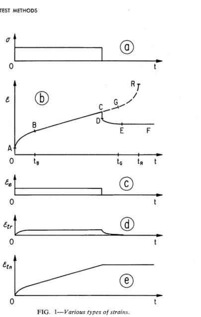
FIG. I-Various types of straitis.
It has long been recognized that the simplified concept that the de- formation of solids is a quasi-instantaneous response to loading has very definite limitations. Although it is known that at sufficiently high tem- peratures the deformation is governed by the creep properties of the solid, the lack of knowledge concerning these properties and of well- established design procedures has prevented engineers from taking creep into account in various fields of engineering design. One of these fields is the design of building elements for fire endurance.
In this paper information will be given on the creep characteristics of a structural steel, and a calculation procedure will be presented which, although developed primarily for predicting the deflection and point of
H A R M A T H Y ON DEFLECTION A N D FAILURE O F STEEL-SUPPORTED F L O O R S 43
failure of steel-supported constructions2 in fire, may find application in other fields of engineering, where the creep deformation of metals at variable temperatures and loads is of interest.
To apply this calculation technique, one must know the temperature history of the steel components of the construction (or of the metal form to be examined, in general). Since the technique of carrying out numeri- cal heat flow analyses has already been described [1,2],3 in this paper the temperature history of the steel components will be regarded as available basic information.
Elastic Strain and Creep Strain
During the past four decades numerous theories have been evolved by noted research workers to explain the time-dependent deformation of metals, caused by the application of stress. Unfortunately, the terminol- ogy is still far from being uniform; it is necessary, therefore, to include a brief note about the terminology to be used in this paper.
In Fig. l b the strain history of a steel specimen is shown, at constant temperature, following the stepwise application of a constant tensile stress (more accurately: a constant load), as shown in Fig. la. T o avoid many apparent contradictions now frequently found in the literature, in this paper any time-dependent deformation process will be referred to as creep, and the resulting deformation, e t , as "creep strain." Accordingly, the ABC and DE sections of the OABCDEFcurve are creep strain curves, or briefly, "creep curves."
The strain history curve shown in Fig. l b is typical of t = e(1) curves obtainable with conventional creep tests, that is, with tests at T = const and u = const for 1
>
0. Its initial vertical section, OA, represents the quasi-instantaneous response of the material to loading. Following this response, creep sets off at a high, but steadily decreasing, creep rate, i1(=dtl/dl), over the period 0<
I<
I , < . Later i 1 attains a value which will remain approxiniately unchanged over the relatively long period of I,<
II:
I,; (provided the load is left on indefinitely). Finally, owing to soiiie localized reduction in the cross-sectional area of the specimen, the creep rate will steadily increase again (over the period I,<
t5
I,) up to the point of rupture. These three periods are conlmonly referred to as primary, secondary, and tertiary periods of creep, respectively. From a practical point of view the creep during the secondary period is by far the niost important. The approxiniately constant value of the creep rate during this period is called "secondary creep rate," arid is denoted by it,.
The total load strain (strain caused by the application of load), t , may be regarded at any time as consisting of three terms. These terms are plotted separately in Figs. lc, d, and e. The quasi-instantaneous response
'This treatise is not applicable to prestressed concrete.
T h e italic numbers in brackets refer to the list of references appended to this paper.
4 4 FIRE TEST M E T H O D S 4 0 I I I I I 1
-
-
-
A-
\o A-
" . a n-
-
-
\:
0-
Source:-
0 Lea and Crowther (3) A ~ e r s e ' ( 4 ) o Garofalo et at ( 5 )
-
-
I I I I I I 0 200 4 0 0 6 0 0 8 0 0 1 0 0 0 1 2 0 0 1 4 0 0 T e m p e r a t u r e , FFIG. 2-Modulus of elasticity o f carbot~ stccls.
to loading is the familiar elastic strain, t,.
,
which is known to obeyHooke's law,4
t,: = a / E . . . . . . . . . . . . . . . . . . . . . . (1)
arid to be completely recoverable upon the removal of the load.
The modulus of elasticity, E, is a material property known to be rela- tively insensitive to the microstructure of the material. The dependence on teniperature of E for structural steels is plotted in Fig. 2.
4 6 FIRE TEST M E T H O D S
The creep strain consists of a recoverable and a nonrecoverable part. The recoverable part, e r r , is called "anelastic strain." The nonrecover- able time-dependent strain, c,,
,
is generally referred to as "plastic creep strain." With the types of problems to be discussed in this paper, all time-dependent strains may be regarded as essentially nonrecoverable, that is, e r z e r n and cL, z 0, therefore for convenience the shorter term "creep strain" will be used hereafter i n place of "plastic creep strain."From among the most widely accepted deformation theories, that pro- pounded by Dorn [6,7] has been selected for use in this paper, not only because of its merits, but also because of the advantages it offers in numerical creep analysis. The basis statement of Dorn's theory is as follows. In the deformation processes that develop at some constant stress level, the creep strain is a unique function of the stress and of a so- called "temperature compensated time," 0,
t r = ct(B,u) for da/df = 0 (when I
>
0) (2) where is defined as0 = e - ( A l * / ~ ~ ) f . . . . . . (for T = const) (3a) The activation energy for creep, AH, is insensitive to the microstructure of the material, and is approximately equal to the activation energy for self-diffusion (about 140,000 Btu/lb mole in the case of iron).
In Fig. 3 a family of c r versus
e
curves for an A36 steel is shown atseveral u = const values within the domain of main practical interest. These curves represent some of the results of a comprehensive creep study still in progress in the DBR Fire Research laboratory [ 9 ] . These curves also exhibit straight-line sections which, if the temperature is held constant, extend over the intervals corresponding to the secondary period of creep. Dorn's theory implies that the slope of the straight-line section of any t , versus 0 curve (which is commonly referred to as the Zener-Hollornon parameter [ 8 ] , and is denoted by Z), and the intercept, t , ,
,
obtained by extending the straight-line section to the e l axis, are uniquely determined by the applied stress [ l o ] , that is,and
HARMATHY O N DEFLECTION A N D FAILURE O F STEEL-SUPPORTED FLOORS A 7
F I G . 4-Cenernlized creep curve.
Although the applicability of Dorn's theory is generally restricted t o creep processes occurring at temperatures above one half of the melting temperature, in the case of carbon steels it seemed to be applicable within the 750 t o 1300 F interval, which actually represents the entire temperature range of practical interest.
T o make Dorn's theory applicable to the study of the deformation history of steel structures in fire, it was necessary to expand it by intro- ducing two plausible assumptions. With the aid of these assumptions the following equations were obtained [ l o ] :
48 FIRE TEST M E T H O D S
1 2 4 6 8 10 15 20 30 40 50 60
fl 1000 psi
FIG. 5-Zener-Hollomon parameter versus stress correlation for an A 36 steel.
and
Equation 6 can be used to calculate creep deformation occurring at constant stresses. To facilitate such calculations, in Fig. 4 the group
HARMATHY O N DEFLECTION AND FAILURE O F STEEL-SUPPORTED FLOORS 49
0 200 400 600 800 1000 1200 1400
T e m p e r a t u r e , F
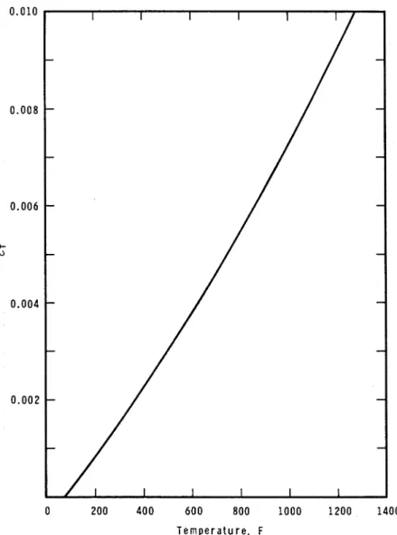
FIG. &Thermal expansion o f an A 36 steel (annealed).
has been plotted against the ZO/e,, group, with the aid of Eq 6. Equation 7, in the following finite difference form,
AO. . . (9) can be utilized whenever the du/dt condition is not fulfilled.
From the point of view of the problems on hand, tertiary creep is not important; therefore, it will not be discussed here any further.
50 FIRE TEST METHODS
5 have to be determined experimentally. For the A36 steel examined a t the Division of Building Research, A H / R
z
70,000 deg R. The Zener- Hollomon parameter has been plotted against stress in Fig. 5. The experimental points may be approximated by the following expressions:( 0 . 0 2 6 ~ ~ . ~ . . . . .if u
5
15,000 psiz =
{. . .
j1.23 X 101Ge0.00035. .for 15,000
<
u<
45,000 psi) The intercept term for the same steel can be calculated by the following empirical formula:€,, = 1.7
x
10-10u'~75. . . .(11) The "theoretical curves" shown i n Fig. 3 have been plotted with the aid of these expressions, and of Eq 6.Owing to the relatively minor role that compressive creep may play in the problems on hand, it will be assumed here that every relationship introduced so far is applicable to both tensile and compressive deforma- tions. In agreement with the conventions, compressive stresses and strains indicating a shortening of the fibers will be regarded as negative quantities.
Thermal Strains
So far only strains associated with the application of load have been discussed. There is another kind of strain additive to the load strain, but practically independent of the load: the strain caused by the thermal expansion of steel. This thermal strain, C T
,
is an instantaneous responseto the temperature variation and, if the temperature does not exceed 1300 F, is completely recoverable.
Because of the additivity of the load strains and the thermal strain, the total strain is given by
In Fig. 6 the thermal strain of carbon steels is plotted against the temperature, based on the information given in Ref 11. It is well known that such E T versus T relations are relatively insensitive to the microstruc-
ture of the material.
The thermal strain corresponding t o a change in the temperature from Tl to TI can be taken approximately as
Obviously, the thermal strain is positive if TI
>
T I , and negative if TI<
T l .Deflection of Steel Joists and Trusses in Fire
As an example of the use of the information presented in the previous sections, the deformation history of a steel joist of a commonly used, so-
HARMATHY ON DEFLECTION AND FAILURE OF STEEL-SUPPORTED FLOORS 51
(a) Diagrammatic picture of the floor assembly.
(1) Steel joist.
(2) Metal lath. (3) Sprayed asbestos. (4) Brick.
(b) Stress distribution in the steel joist (stresses in psi:
+
= tensile,-
= com- pressive)(c) Stress diagram of the steel joist. (d) Simplified model of the steel joist.
FIG. 7-The Poor assembly examined in Exanlple 1
called membrane-protected, floor and ceiling assembly during a fire test will be discussed (Example 1). The geometry of the joist is shown dia- grammatically in Fig. 7a. Since the load-bearing capacity of the deck and membrane is obviously negligible, the stresses in the members of the joist are calculable from the imposed load, and can be taken as approximately constant throughout the fire test. The stress distribution in the structure is shown in Fig. 76.
HARMATHY O N DEFLECTION AND FAILURE OF STEEL-SUPPORTED FLOORS 5 3
The joist is assumed to have been built from A 36 steel. The tempera- tures of the lower chord, the web members, and the upper chord are assumed to vary in the way shown in Fig. 8a. The various steps involved in the deflection analysis can best be followed by inspecting Figs. 8b to i. To plot Figs. 8b to g, in addition to the basic information [the stress distribution (Fig. 7b) and the temperature history (Fig. Sa)], the graphs in Figs. 2, 4, and 6, and Eq 10, 11, and 13 were utilized. The .4 versus time plot in Fig. 8e was obtained, in accordance with Eq 3, by measuring the areas under the curves in Fig. 8d.
,To plot the deflection history of the joist in Fig. 8i the following ex- pression was used:
which, in a form restricted to the calculation of elastic deflections of steel trusses, is well known from various sources.
From a practical point of view the deflection at the center of the joist,
y,
,
is of primary interest. The values of s, for calculating y, can be deter- mined graphically from the stress diagram obtained by applying a 1-lb load to the central joint, as shown in Fig. 7c.By virtue of Eqs 12 and 14, deflections caused by various types of strains are additive,
In Fig. 8i these three components of the central deflection of the joist are also plotted separately.
It is seen from Fig. 8i that as the temperature of the lower chord ex- ceeds 900 F, quickly developing creep primarily in members 8, 12, and 16, as shown in Fig. 8h, results in rapid increase in the deflection. The joist would fail shortly after 2 hr, 30 min.
According to Fig. 8g, at the time when failure is due to occur, member 12 of the joist is already in the secondary period of creep.
Since the final stage of fire exposure is governed entirely by the creep of the central member in the lower chord (member 12), the time of failure can be conveniently studied with the aid of a simplified model of the joist, based on a "key member" concept, such as that shown in Fig. 7d. For this model the central deflection can be expressed as
In Fig. 8i the deflection history of this model is also shown by a dashed line.
A somewhat unusual feature of the deflection curves shown in Fig. 8i is their very steep rise after the temperature of the lower chord exceeded
54 FIRE TEST M E T H O D S
(a) Actual beam assembly
(1) Steel beam W F 12 by 69'2, 27 Ib/ft, A = 7.97 in." I = 204.1 in.', r = 5.06 in.
(2) Concrete deck A d = 150 in.', I d = 78.1 in.'
(3) Steel sheet deck plate. (4) Sprayed insulation.
(b) Temperature distribution in the beam at one particular time (c) Stress distribution at one particular time
(d) Strain distribution at one particular time (e) The l / p versus x plot at one particular time (f) The dy/dx versus x plot at one particular time
(g) Deflection of the beam at one particular time (h) Simplified model of the beam assembly ( i ) Idealized cross section of the steel beam
FIG. 9-Tlrc heam asscr?~bly examitled itr E x a m p l ~ 2 .
1000 F. This steep rise occurs because all components except the joist
of the floor assembly are incapable of carrying any load. In actual floor asseniblies the load-carrying capacity of the deck is fiir from being negligi- ble. Since the temperature of the deck is always the lowest of any part of an assembly, the deck is capable of sustaining an increasing portion of
HARMATHY ON DEFLECTION A N D FAILURE OF STEEL-SUPPORTED FLOORS 55
the load and transferring it directly to the walls, as the deflection of the steel supporting element increases. Based on a priori reasoning, the fol- lowing expression has been derived to describe the relief of load on, or the stresses at any location in, the steel supporting element:
where
The reciprocal of yc* will be referred to hereafter as the "load resistance" of the deck. It can be determined experimentally by measuring the deflec- tion of the assembly under a given load:
where y, is the measured deflection, and
y,
is the deflection that the steel supporting element alone would exhibit under the same load (to be ob- tained by calculation).When the load resistance of the deck is not negligible, the deflection history of the assembly has to be calculated by a followup technique which will now be described.
Deflection of Beams in Fire
The building element to be studied as Example 2 is shown and de- scribed in Fig. 9a. It is a beam assembly similar to those subjected to fire tests recently at Ohio State U n i ~ e r s i t y . ~
In general, the bending moment in beams varies along their length. In this way shear stresses are produced, which result in deflections addi- tional to those resulting from bending. These shear stresses are, however, negligible for beams which are long in comparison with their depth; therefore, shear deflections will not be taken into account in this paper.
The "classical" way of calculating the deflection history of steel beams consists of numerous calculations aimed at finding the deflected shape of the beam a t sufficiently small time intervals. The calculation technique has been described by Popov [12] and Mordfin [13]. The basic informa- tion here, too, is the temperature history of the beam, and the original load distribution. The operations to be performed for each time interval can be understood by examining Figs. 96 to g . The curvature of the beam, lip, at a few locations along the length of the beam is obtainable from
58 FIRE TEST METHODS ,
(!
3? , , 6? ,j7,
400 200 50---
40 30 chonqe of scale 2 20g
10 ---.
8 ' 6lime min lime min
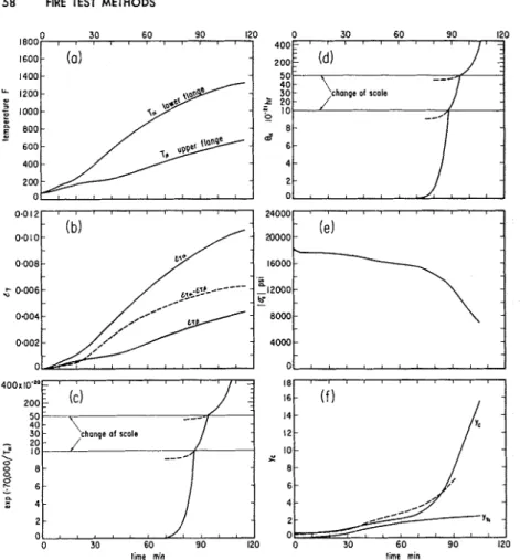
FIG. 10-ldealized calculation o f the deflection o f the beam assembly shown in Fig. 9 (see text for details).
the strain-distribution plot (Fig. 9d), with the aid of the following expres- sion
From the well-known relation :
they = y(x) deflection curve can be finally obtained by repeated graphi- cal integration of the I l p versus x curve.
This calculation procedure may well be adoptable for computer studies, but it is much too laborious for engineering purposes. To simplify the calculations, the following assumptions will be used:
HARMATHY ON DEFLECTION A N D FAILURE OF STEEL-SUPPORTED FLOORS 5 9
1. The load is uniformly distributed along the length of the beam. An "equivalent uniform load," W , , [nay be defined as that which pro- duces the same niaximuni bending moment as the actual load. For the assembly examined,
. . .
W,, = 8 Pd/L2. (22)
2. The cross section of the beam can be satisfactorily represented by two rectangular plane surfaces, "flanges" [14], which offer the same area a r d moment of inertia, as the original section (Fig. 9i). For this idealized section
3. The temperatures in the lower and upper flanges do not vary along the length of the beam.
4. The shape of the deflected beam is satisfactorily described by a sine curve. Utilizing Eq 20, the central deflection can thus be expressed as
where h % 2r
With the aid of these assumptions the inforniation of only practical interest, the history of central deflection, is obtainable by examining the stresses and strains at the midspan alone.
The simplified calculations concerning the deflection history of the beam assembly shown in Fig. 90, and in simplified form in Figs. 9h and i,
are presented in Table 1 . For this assembly k , = 146 Ib/in. (Eq 22),
I
a,,,I
= 18,470 psi (Eq 22), and with E,, z 3 X lo"< yy,* = 13.51 i n . (Eq 18). The temperature history of the lower and upper flanges has been plotted (based on information presented by Bletzacker, see Footnote 5 ) in Fig. 10n.The calculations i n each row of the table are aimed at obtaining a new value of J;. by the end of a 5-min interval (Colunln 12). This value is then used to find the values of iT, (Eq 17) and
I
a,I
(Eq 23) applicable t o the next time interval.As the temperature of the upper flange never becomes high enough to allow development of creep strains, t ~ , (Column 5) is equal throughout
with the elastic strain, t , J ,
.
111 the lower flange, on the other hand, after 65-min fire exposure the creep strain, t , , , , (Column 1 l ) , qi~ickly becomesthe main component of to, (Column 4). From 75 min on, t l , , is calculated
by repeated application of Eq 9. The details of these calculations are given in Colunins 7 through 11. The values of Z,, are found by using Fig. 5. Those of At, can be determined with the aid of the curve in Fig. 10d, which w;is obtained by graphical integration of the curve in Fig. lor. The thermal component of the deflection, y,, , was calculated
60 FIRE TEST METHODS
separately, using Fig. lob and the appropriate form of Eq 24, and is plotted, in addition to the total deflection, in Fig. 10J In Table 1, y,,
is added to the load deflection in Column 12.
The values of the hyperbolic cotangent term (Column 8) indicate that, according to Eq 7, the central portion of the lower flange of the beam enters the secondary period of creep at about 90 min.
To illustrate the progress of stress relief, the calculated
I
a, ( versus time curve is shown in Fig. 10e.An experimental deflection curve obtained by the Ohio State Uni- versity5 for this assembly is shown as a dashed line in Fig. 10J The agree- ment between the theoretical and experimental curves is satisfactory from an engineering point of view.
In the case of fully restrained beams the bending moment at the mid- span is only one third of that for simply supported beams. Because of this, and the greater stability provided by the fixed ends, restrained beams are expected to function in fire better than simple beams. Since the degree of actual restraint is never known, and the simple support represents the most adverse conditions, it would be in accordance with good engineering practice to regard simple support as standard in fire endurance investigations.
Temperature Criteria of Failure
Based on an examination of 50 fire test reports, Robertson and Ryan
[15] found that the structural failure of floors and beams could be satis-
factorily defined as the point at which
It will be shown now that, with the aid of these two "deflection criteria,'' temperature criteria of structural failure can also be found.
In the final stage of fire exposure the rate of deflection, dy,/dt, is always a monotonic increasing function of time. Because of this one must be able to find, corresponding to any arbitrarily selected but sufficiently high "limiting" rate of central deflection, ( d ~ , / d t ) ~ , a time limit within which, after reaching this selected "limiting" rate of deflection, failure will occur for any type of steel supporting element.
By making use of the differentiated forms of Eqs 16 and 24, and of Eq 4 (by virtue of the fact that at the final stage of fire exposure the deflection is governed by the secondary creep rate in the lower flange (or member) at the midspan), and furthermore, by accepting the second Robertson-Ryan criterion as ( d ~ , / d t ) ~
,
the following two equations can be derived:HARMATHY O N DEFLECTION A N D FAILURE O F STEEL-SUPPORTED FLOORS 61
AH/ R
T -
- In [37.5[lk/L)Zk]
. . (for joist, truss) (27)
These equations, in entirely general form, are the temperature criteria of structural failure for steel joists and trusses, and beams, respectively, during fire exposure.
To apply these to particular constructions one must know ( 1 ) the activation energy of creep, AH, and the Z = Z(a) relation for the steel employed, and (2) the value of ak or a,, at a time "reasonably close to the structural failure."
For A 36 steels, AH/R = 70,000 deg R. The Z = Z(u) relationship has been given by Eq 10. (Here, because of the load-relieving effect of the deck, the expression for a
I
15,000 psi is applicable.)With the aid of the first Robertson-Ryan criterion and Eqs. 17 and 18, expressions can be derived for uk and a,, at a time reasonably close to the point of failure, in terms of U, (the allowable stress for steel), E d , I d ,
and 1. Taking U, = 20,000 psi and Ed = 3 X 10"si (for concrete), the following simple temperature criteria are finally obtained:
-460 (in deg F ) . . . . (joist, truss) (29)
460 ( in deg F ) . . bean^)^ (30)
Utilizing these formulas, the time of failure for the joist (Example 1) is 2 hr 29 min, and for the beam (Example 2) 1 hr 25 min, which are in good agreement with the information obtained by calculations or experi- ment.
The limiting temperatures calculated by Eqs 29 and 30 usually range between 1074 and 1231 F, depending on the moment of inertia of the deck.
In conclusion, attention is called to the fact that, although the tempera- ture in the lower chord (or flange) at the midspan is the most decisive factor in the failure of steel-supporting elements, A S T M Melhods E 119
do not even require the recording of this itformation.
O Recent DBR test results indicate that a better agreement between experimental
and calculated data can be obtained if T,, is interpreted as the average tempera- ture of the lower half of the beam at the midspan, instead of as the temperature of the lower flange at the midspan.
62 FIRE TEST METHODS
References
[ I ] Harmathy, T. Z., "A Treatise on Theoretical Fire Endurance Rating," Firc Test Methods, A S T M S T P 301, American Society Testing and Materials, 1961, p. 10.
[2] Harmathy, T. Z., "Effect of Moisture on the Fire Endurance of Building Elements," Moisture in Materials in Relation t o Fire Tests, A S T M S T P 385, American Society Testing and Materials, 1965. p. 74.
[3] Lea, F. C., and Crowther, 0. H., "The Change of the Modulus of Elasticity and of Other Properties of Metals with Temperature," Etlgineering, Vol 98,
1914, p. 487.
[ 4 ] Verse, G., "The Elastic Properties of Steel at High Temperatures," Transac-
tiorls, American Society Mechanical Engineers, Vol 57, 1935, p. I .
[5] Garofalo, E., Malenock, P. R., and Smith, G. V., "The Influence of Tem- perature on the Elastic Constants of Some Commercial Steels," Detcrmil~ation o f Elnstic Cotlstar~ts, A S T M S T P 129, American Society Testing and Mate- rials, 1952, p. 10.
[6] Dorn, J . E., "Some Fundamental Experiments on High Temperature Creep," Jo~rrr~al of tlre M r c l ~ a ~ r i c s and Pllysics of Solids, Vol 3, 1954, p. 85.
[7] Dorn, J. E., "Progress in Understanding High-Temperature Creep," Ameri- can Society Testing and Materials, Gillett Memorial Lecture, 1962.
[8] Zener, C., and Hollomon, J. H., "Effect of Strain Rate on the Plastic Flow of Steel," Jolrr~~trl of Applied Pl~ysics, Vol 15, 1944, p. 22.
[9] Harmathy, T . Z., and Stanzak, W. W., "The Creep Properties of Structural Steels," to be published.
[I01 Harmathy, T. Z., "A Comprehensive Creep Model," ASME Publ. No. 67- MET-20, presented at the Metals Engineering Conference, Houston. Tex., April 3-5, 1967.
[ I ] ] Perry, J. H., "Chernic;~l Engineers' H;~ndbook," 3rd ed., McGraw-Hill, New York. 1950. . D.
.
200.1121 POPO;, E. P., "Bending of Beams with Creep," Jorrr~~al o f Applied Plrysic.~,
-
- . ~v o i 20, I 949, p. 25 I .
-
[I31 Mordfin. L.. "Analvtical Studv of Creep Deflection of Structural Beams." NASA T N D-661, ~ a t i o n a l ~ e r o n a u t i c s :lnd Space Administration, 1960.
. [I41 Odqvist, F . K . G . , and Hult, J.. Krieclrfesti.qkcit ~ ~ ~ e t c ~ l l i s c l ~ c r . Wcrkstoffe,
Springer-Verlag, Berlin, 1962, p. 86.
[I51 Robertson, A. F., and Ryan, J. V., "Proposed Criteria for Defining Load Failure of Beams, Floors and Roof Constructions During Fire Tests," Jorrrr~al of Researcl~, National Bureau of Standards, Vol 63C, 1959, p. 121.