HAL Id: hal-01203105
https://hal.inria.fr/hal-01203105
Submitted on 22 Sep 2015
HAL is a multi-disciplinary open access
archive for the deposit and dissemination of
sci-entific research documents, whether they are
pub-lished or not. The documents may come from
teaching and research institutions in France or
abroad, or from public or private research centers.
L’archive ouverte pluridisciplinaire HAL, est
destinée au dépôt et à la diffusion de documents
scientifiques de niveau recherche, publiés ou non,
émanant des établissements d’enseignement et de
recherche français ou étrangers, des laboratoires
publics ou privés.
An Efficient, Portable and Generic Library for
Successive Cancellation Decoding of Polar Codes
Adrien Cassagne, Bertrand Le Gal, Camille Leroux, Olivier Aumage, Denis
Barthou
To cite this version:
Adrien Cassagne, Bertrand Le Gal, Camille Leroux, Olivier Aumage, Denis Barthou. An Efficient,
Portable and Generic Library for Successive Cancellation Decoding of Polar Codes. The 28th
In-ternational Workshop on Languages and Compilers for Parallel Computing (LCPC 2015), Sep 2015,
Raleigh, United States. �10.1007/978-3-319-29778-1_19�. �hal-01203105�
An Efficient, Portable and Generic Library for
Successive Cancellation Decoding of Polar Codes
Adrien Cassagne1,2, Bertrand Le Gal1, Camille Leroux1, Olivier Aumage2, and
Denis Barthou2
1
IMS, Univ. Bordeaux, INP, France [email protected]
2 Inria / Labri, Univ. Bordeaux, INP, France
Abstract. Error Correction Code decoding algorithms for consumer products such as Internet of Things (IoT) devices are usually imple-mented as dedicated hardware circuits. As processors are becoming in-creasingly powerful and energy efficient, there is now a strong desire to perform this processing in software to reduce production costs and time to market. The recently introduced family of Successive Cancella-tion decoders for Polar codes has been shown in several research works to efficiently leverage the ubiquitous SIMD units in modern CPUs, while of-fering strong potentials for a wide range of optimizations. The P-EDGE environment introduced in this paper, combines a specialized skeleton generator and a building blocks library routines to provide a generic, extensible Polar code exploration workbench. It enables ECC code de-signers to easily experiments with combinations of existing and new op-timizations, while delivering performance close to state-of-art decoders. Keywords: Error Correction Codes, Polar Codes, Successive Cancella-tion decoding, Generic programming, Code generaCancella-tion, Domain Specific Language, SIMDization
1
Introduction
Error correction coding aka channel coding is a technique that enables the trans-mission of digital information over an unreliable communication channel. In to-day’s communication systems, hardware digital circuits are in charge of perform-ing the encodperform-ing (resp. decodperform-ing) of transmitted (resp. received) information. These custom Error Correction Code (ECC) circuits lack flexibility and suffer from very long, expensive development cycles. In order to improve the system flexibility and to reduce time to market, and as a consequence from the strong performance increase of low power general purpose processors such as found in IoT devices, researchers recently suggested implementing channel decoders in software. Moreover, it is also much needed to be able to run such algorithms on high end, high performance processors to shorten the computationally intensive algorithm validation process. During such a process, long sequences of informa-tion are encoded with the studied algorithm, altered with a controlled random
noise, decoded, and compared with the initial sequence to assess the error cor-recting power. Indeed, some classes of decoding algorithms can take advantage of modern CPU features such as SIMD units, and even many/multi-cores, making the software approach even more desirable.
In this paper, we focus on the software implementation of Successive Cancel-lation (SC) algorithm for a recent family of error correction codes: Polar Codes [2]. As an alternative to hardware implementation, several recent software im-plementations were proposed in the literature in order to demonstrate that po-lar codes decoding can be efficiently implemented on a multi-core CPUs (x86, ARM). These software implementations take advantage of various optimizations that were first proposed for hardware implementations. However, depending on the processor micro-architecture and instruction set, some optimization tech-niques may not work equally on distinct processors. New optimization techtech-niques may be designed. Some optimization combinations may be less successful than others. As a result, the optimization space of polar decoder implementations is wide, and its exploration non trivial.
For this reason, we propose a new polar decoder experimentation framework named P-EDGE (Polar ECC Decoder Generation Environment), which combines a specializing skeleton generator with a building block library of elementary po-lar code processing routines. The algorithm-centric skeleton generator is fully independent from the hardware architecture enabling high-level algorithmic op-timization to be implemented in a portable manner. The architecture-centric building block library is fully independent from the generated skeleton instance, enabling architecture porting effort and low-level routine optimization to be concentrated on a small set of short functions. P-EDGE enables separation of concerns between algorithmic and architecture optimizations. The panel of eval-uation experiments we conducted shows the high flexibility of our framework. The performance evaluation results we obtained, nearing and sometime outper-forming state-of-the-art handwritten implementations, confirm that the benefit from this high flexibility is not cancelled by an expensive penalty.
The remainder of this paper is organized as follows. Section 2 details the context and relevant characteristics of the general polar code decoding process, as well as the large optimization space resulting from its implementation. Sec-tion 3 presents our proposed framework as well as the architecture independent skeleton generator. Section 4 provides implementation details on the architec-ture dependent building blocks. Section 5 talks about the achieved related works in the domain. Section 6 shows experiments and performance results. Section 7 concludes the article.
2
Successive Cancellation decoding of Polar Codes
Error correction codes are widely used in digital communication and data storage applications. The encoding process consists in adding some redundant informa-tion (parity check bits) in order to strengthen the message against transmission errors. On the receiver side, the decoder estimates the transmitted bits based
on i) the received sequence and ii) the knowledge of the encoding process. Polar Codes were recently proposed in [2]. Similar to state of the art LDPC codes [4] [9] and Turbo codes [3], polar codes can achieve very good error correction
performance. However, a very large codelength (N > 220) is required in order
to approach to the theoretical error correction limit proved by Shannon [13]. The challenge is then to design polar codes decoders able to decode several mil-lions bits frames while guaranteeing a compelling throughput. Assume we want
to transmit K bits over a noisy communication channel. The encoding process
appendsN − K parity check bits before the resulting N bits codeword can be
transmitted over the channel. On the receiver side, the noisy sequence Y is a
vector ofN real values each corresponding to a priori beliefs on the transmitted
bits. These beliefs are in the form of a Log-Likelihood-Ratio (LLR). Using the knowledge of the encoding process, the decoder job is to estimate the transmitted N -bit codeword based on a received sequence of N LLRs.
4 3 2 1 0 Depth 1 3 l l+1 l+1 f g h 2
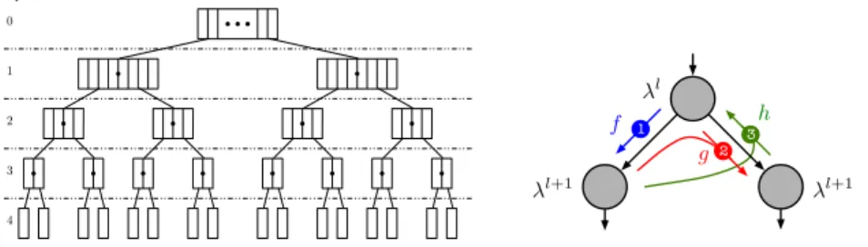
Fig. 1. a) Tree layout. b) Per-node downward and upward computations.
The SC decoding algorithm can be seen as the traversal of a binary tree
starting from the root node. For a codelength N = 2m, the corresponding tree
thus includes m + 1 node layers, indexed from l = 0 (root node layer) down
to l = m (leaf nodes layers). As the tree is initially full, each layer l contains
2l nodes, each node of that layerl containing 2m−l LLRs (λ) and 2m−l binary
values denoted as partial sums (s). At initialization, LLRs received from the channel (Y ) are stored in the root node. Then, the decoder performs a pre-order traversal of the tree. When a node is visited in the downward direction, LLRs of the node are updated. In the upward direction, partial sums are updated. Fig. 1b summarizes the computations performed in both directions. The update functions are: λc = f (λa, λb) = sign(λa.λb). min(|λa|, |λb|) λc = g(λa, λb, s) = (1 − 2s)λa+ λb (sc, sd) = h(sa, sb) = (sa⊕ sb, sb). (1)
The f and g functions both generate a single LLR. The h function provides a
couple of partial sums.
Before recursively calling itself on the left node, the algorithm apply thef
applied. At the end (after the recursive call on the right node) theh function is
applied. Thef and g functions use the LLRs (read only mode) from the current
nodeni in order to produce the new LLR values into respectively left and right
ni+1 nodes. Theh function, in the general case (non-terminal case), reads the
bits from the left and right ni+1 nodes in order to update the bit values of the
ni node. For the terminal case, theh function reads the LLRs from itself and
decides the bit values.
Leaf nodes are of two kinds: information bit nodes and frozen bit nodes. When a frozen bit leaf node is reached, its binary value is unconditionally set to zero. Instead, when an information leaf node is reached, its binary value is set according to the sign of its LLR (0 if LLR is positive, 1 otherwise). Once every node in the tree has been visited in both directions, the decoder eventually updates partial sums in the root node and the decoding process is terminated. At this point, the decoding result is stored in the root node in the form of a N -bit partial sum vectors.
2.1 Code Optimization Space
The previous decoder algorithm has a number of characteristics of interest for its optimization. Generating decoders able to take advantage of this optimization space is the key for high performance decoders:
– The tree traversal is sequential, butf , g and h are applied element-wise to
all elements of the LLR and bits in the nodes and their children. As there is no dependence between computations involving different elements of the same node, these node computations can be parallelized or vectorized (cf. the intra-frame strategy introduced in [5]),
– Frozen bits fully define their leaf values, hence some part of the traversal can be cut and its computation avoided, depending on the location of the frozen bits. More generally, the tree computation can be versioned depending on these bits (cf. [1] [12]),
– The decoder can be specialized for a particular configuration of frozen bits, as frozen bit locations do not change for many frames,
– Similarly, multiple frames can be decoded concurrently, with parallel or vec-tor code. Such inter-frame optimizations can increase the decoding through-put, however at the expense of latency, which is also one important metric of the application (cf. [8]).
Beside optimizations coming from the computations in the tree, several rep-resentations of LLR may lead to different error correction performance. LLR for instance can be represented by floats or integers (fixed point representation), LLR from different frames can be packed together.
Finally, usual code optimizations, such as unrolling or inlining can also be explored. For instance, the recursive structure of the tree computation can be fully flatten, depending on the size of the codelength.
3
The P-EDGE framework
We now presents the framework we designed to study, experiment with, and opti-mize the decoding of polar codes. While our contributions focus on the decoding stage, a whole encoding/decoding chain is required for testing and validation purpose, and we therefore give an overview of our communication chain.
Receiver Comm. Chan. Transmitter YN VN UK XN Decoder Sink Channel Encoder Source
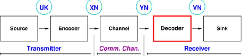
Fig. 2. The communication chain.
Fig. 2 depicts the whole communication chain of our framework. The chain stages are organized as the following main segments:
The Transmitter segment is made of two Stages: 1) The source signal
gener-ator stage (Source) produces the vector of information bitsUKto be transmitted.
2) The polar encoding stage (Encoder ) inserts parity check redundancy bits into
information vector. For every packet of K information bits, a total of N bits
are produced (information+redundancy bits). The resulting N-bit vector (XN)
is transmitted over the communication channel.
The Communication channel segment simulates a noisy communication, adding additive white Gaussian noise to the frames, producing the real vector
YN from the binary vectorXN.
The Receiver segment is made of two Stages: 1) The Decoder stage produces
a binary vectorVN from YN along using the algorithm described above. 2) The
Sink stage eventually compares the K information bits (VK) in VN with UK
in order to count the number of remaining binary errors after the decoding is
performed. The more effective the error correction code is, the closer the VK
bits should be from the UK bits. Resilient errors may come from 1) inherent
limitations in the polar code construction, 2) sub-optimal decoding algorithm, 3) a high noise power in the communication channel. Moreover, while testing new algorithm implementations or optimizations, an abnormally high error rate can also be the sign of a bug.
3.1 The P-EDGE Decoder Generator
Specialized Decoder Skeletons and Building Blocks Library. The tree structure at the heart of SC decoders is fully determined by the parameters of a given code instance: the code size, the code rate (R = K/N ), position of the frozen
? ? level >= 2 ? ? ? ? ? ? ? ? ? ? ? ? ? ? ? ? ? ? ? ? ? ? ? ? ? g1() Single Parity Check
rep() xor() rep() xor0() g0() spc() h() gr() f() f() g() xor() f() h() spc() Rate 1 Rep Repetition SPC Rate 0 Any node Leaf xor()
Repetition, left only Standard Case
Rate 0, leaf childrens Rate 1, leaf childrens
Rate 0, left only
Rep., leaf children
SPC
Rate 1, left only
Level 2+ SPC
Rate 1
Rate 0 Repetition
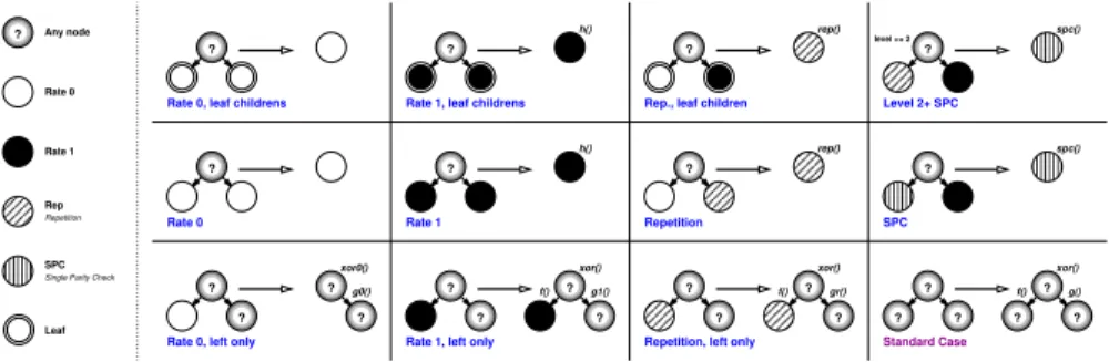
Fig. 3. Subtree rewriting rules for processing specialization.
bits. All these parameters are statically known at compile time. Thus, the recur-sive tree traversal code structure and the corresponding tree data structure are challenging to vectorize and to optimize for a compiler. Our Polar ECC Decoder Generation Environment (P-EDGE) builds on this property to provide a general framework for polar decoder design, generation and optimization. Beyond the code parameters, Polar decoders can be tweaked and optimized in many differ-ent orthogonal or loosely coupled ways: Elemdiffer-entary type (floating point, fixed point), Element containers (array size), Data layout (bit packing techniques), Instruction Set (x86, ARM), SIMD support (scalar, intra-frame or inter-frame processing vectorization), SIMD instruction set variant (SSE, AVX, NEON), as well as the set and relative priorities of the rewriting rules for tree pruning. Our framework enables to quickly experiment the different combinations of all optimizations. The decoder code thus results from two distinct parts:
– An architecture independent specialized decoder skeleton generated by our decoder generator, from a given frozen bits location input. Starting from the naive, recursive expression of the computational tree, we apply successively cuts and specializations on the tree. They are described through a set of rewriting rules, that can be customized according to the specificities of the decoder and to the constraints in term of code size for instance.
– A library of architecture dependent elementary computation building blocks,
corresponding to the implementation variants of the f , g and h functions
(fixed or floating point versions, scalar or vector versions, ...). These blocks do not depend on the frozen bits location and can therefore be used by any specialized skeleton.
This separation of concerns between high-level specialized algorithmic skele-tons and low-level arithmetic routines, enables both ECC experts to focus on op-timizing algorithm skeletons and architecture experts to focus on writing highly optimized routines, without interferences.
Decoder Generation. The decoder generator first builds the binary tree structure as shown in Fig. 1a from the frozen bit location input. Each internal node has
? ? gr() xor() f() f() gr() xor() SPC Rate 0 Rep Rate 1 SPC Rep cut branch void Generated_SC_decoder_N8_K4::decode() { f < R, F, FI, 0, 4, 8, 4>::apply(l ); rep<B, R, H, HI, 8, 0, 4>::apply(l, s); gr <B, R, G, GI, 0, 4, 0, 8, 4>::apply(l, s); spc<B, R, H, HI, 8, 4, 4>::apply(l, s); xo <B, X, XI, 0, 4, 0, 4>::apply( s); }
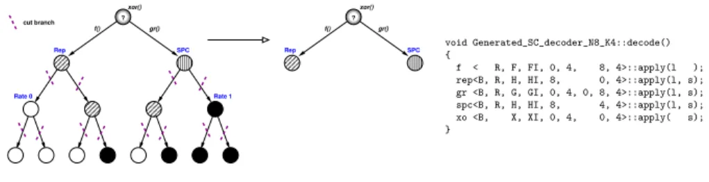
Fig. 4. Generation process on a small binary tree (N = 8). The tree is cut and the computations are versioned according to the location of the frozen bit. The final code generated is in the right.
a tag indicating the type of processing required at that node (recursive children
processing, f /g/h functions to be applied or not). This tag is initially set to
standard, corresponding to the canonical processing described in Fig. 1b. For some sub-tree pattern configurations, the processing to be performed at the root of such sub-trees can be simplified, or even skipped completely, for instance when a node only has two frozen bit leaf children. To exploit such properties, the decoder generator repeatedly applies the set of sub-tree rewriting rules listed in Fig. 3 using a depth first traversal to alter the node tags, until no rewriting rule applies anymore.
Each rewriting rule defines a subtree pattern selector, a new tag for the
subtree root, and the f , g, and h processing functions to be applied, simplified
or skipped for this node in the resulting decoder. A nullf (resp. g) function cuts
the left (resp. right) child of the node. From an implementation point of view, a
rule is defined as a class, with a match function, and a set of functionsf , g, and
h. The current set of rewriting rules can thus easily be enriched with new rules to generate even more specialized versions.
Patterns on the first two rows result in cutting away both children. For instance, the first rule, named Rate 0, leaf children, cuts the two frozen bit leaf children of the parent node, and tag it as Rate 0 (white node). Processing is completely skipped on this node since the values of the bits are unconditionally known. The Repetition rules match subtrees where only the rightmost leaf is black (tag Rate 1 ), the others being frozen bits. In this case, the whole subtree is cut and replaced by a more simple processing. Moreover a single, specialized rep function is applied on the node instead of the three functions f , g and h. The third line describes partial cuts and specialization. For instance, the rule
“Repetition, left only” specializes the g and h functions to use, but does not
prune the recursive children processing.
Rewriting rules are ordered by priority (left to right, then top row to bottom row in Fig. 3), thus if more than one rule match an encountered subtree, the highest priority rule is applied. The priority order is chosen such as to favor strongest computation reducing rules over rules with minor impact, and to ensure confluence by selecting the most specific pattern first. Rules selectors can match
on node tags and/or node levels (leaf, specific level, above or below some level). A given rule is applied at most once on a given node.
Finally, once the tree has been fully specialized, the generator perform a second tree traversal pass to output the resulting decoder. An example of such a tree specialization process together with the generator output is shown in Fig. 4.
4
Low Level Building blocks
template <typename R> R f_seq(const R& la,
const R& lb) {
auto abs_la = (la >= 0) ? la : -la; auto abs_lb = (lb >= 0) ? lb : -lb; auto min_abs = std::min(abs_la, abs_lb); auto sign = (0 < la*lb) - (la*lb < 0);
auto lc = (R)sign * min_abs;
return lc; }
template <typename R>
mipp::vec f_simd(const mipp::vec& la, const mipp::vec& lb) {
auto abs_la = mipp::abs <R>(la );
auto abs_lb = mipp::abs <R>(lb );
auto min_abs = mipp::min <R>(abs_la, abs_lb);
auto sign = mipp::sign<R>(la, lb );
auto lc = mipp::neg <R>(min_abs, sign ); return lc;
}
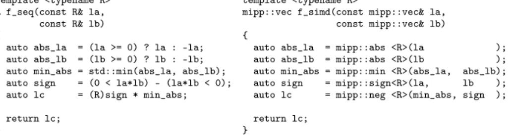
Fig. 5. Example of the C++ implementation of the f function in P-EDGE (the se-quential version is in the left whereas the SIMD one is in the right).
The main challenge in implementing P-EDGE’s architecture dependent build-ing blocks is to provide enough flexibility to enable varied type, data layout and optimization strategies such as intra-frame SIMDization (intra-SIMD) and inter-frame SIMDization (inter-SIMD), without breaking the high level skele-ton abstraction. To meet this requirement, our building block library heavily relies on generic programming and compile time specialization by the means of C++ templates, in a manner inspired by expression template techniques [15]. Template specializations provide node functions. Fig. 4 gives a example of a
generated decoder for N = 8, calling template instances of the node functions.
B: partial sum type; R: LLR/λ type; F/G/H/X: Scalar standard SC function ver-sions; FI/GI/HI/XI SIMD versions. Remaining template parameters are offsets and chunk sizes to control data layout.
A single SIMD set is needed because SIMD routines are common to both intra-SIMD and inter-SIMD. In the later case, the generated decoder packs as many frames together from the frame stream as the vector size in a transparent manner. In both cases, offsets are fully precomputed at compile time. Intra-SIMD exploits Intra-SIMD units without increasing the decoder latency, since it still processes frames one at a time and thus preserves fine grain frame pipelining. However, at leaf nodes and nearby, too few elements remain to fill SIMD units. For instance, 4-way SIMD registers are fully filled only at level 2 and above. Thus, Intra-SIMD will only be effective on trees that can be heavily pruned from these numerous scalar nodes. Inter-SIMD does not suffer from this problem, since SIMD register lanes are filled by LLRs and bits from multiple frames instead.
However, the decoder needs to wait for enough frames to arrive, which increases latency, and to interleave the LLRs from these frames (gather ) before proceeding. It also needs to de-interleave the resulting data (the bits) after decoding (scatter ). Refer to [8] for more details about the interleaving process.
The framework instantiates scalar or SIMD functions as appropriate (hence the two sets of functions). These two sets of functions are themselves independent on the element type. Scalar functions are datatype-parametered templates. SIMD functions use the template-based MIPP intrinsics wrapper library developed by one of the authors to benefit from SSE, AVX and NEON flavors SIMD instruction sets in a portable and extensible manner. As an example, the generic scalar and
SIMD implementations of the f function are shown in Fig. 5. We also tried an
auto-vectorized approach but even if all the routines were well vectorized (from the compiler report), the performance was, at least, 3 times slower than the MIPP handwritten versions.
The decoder stores its state using two data buffers, one for the LLR values (λ) and the other for the bits (partial sums s). The “logical” tree layout is implemented as a simple and efficient heap vector data layout. Traversing the tree therefore corresponds to moving through the array, at different offsets and considering different index intervals. The LLR offset is computed from the graph
depthd (or the node vertical indexing) as follows:
of fλ(d = 0) = 0, of fλ(d > 0) = d X i=1 N 2i−1. (2)
Given l the lane (or the node horizontal indexing), the bit offset is determined
as follows:
of fs(d, l) = N
2d × l. (3)
The LLR buffer size is2N and the bit buffer is N , for a frame of N bits. Thus,
the memory footprint per frame is:
memf p = N × (2 × sizeof (LLR) + sizeof (bit)). (4)
LLRs element size is 4 bytes (float) or 1 byte (fixed point numbers). The Inter-SIMD version also employs a bit packing memory footprint reduction tech-nique [8] to pack several bits together by using shifts and masking instructions.
5
Related works
Polar codes [2] keep on gaining attention from circuits and systems designers. The practical interest of these codes comes from the possibility to implement them efficiently in software. Software implementations were proposed in [5] on x86 processor targets, using SIMD instructions to speed-up single frame decoding (intra-frame parallelism). In addition to SIMD optimizations, the tree pruning step described in section 3 was also applied to the decoder in [12]. Moreover, fixed point representation was implemented in order to speed up the decoding process.
This modification of the data format has a negligible impact on error correction quality while enabling better throughput. The authors proposed to improve the throughput performance by auto-generating the source code of their floating point decoders [11]. A second set of works [8] has considered an another way to take advantage of SIMD processing capabilities. Authors focused on inter-frame parallelism using both SIMD and multi-thread parallelization. Indeed, this ap-proach enables constant parallelism level during the overall decoding process, at the cost of an increased latency. Throughputs achieved using this approach and the associated implementation optimizations were about ×4 to ×8 times higher than [5]. An ARM-based implementation was also explored in [7] to enable low power consumption software decoding for a potential use on consumer devices.
The P-EDGE philosophy differs from these previous approaches by promot-ing separation of concerns and genericity as first class objectives to enable exper-imenting with multiple optimization strategies. Results presented in Section 6 show that these objectives are not incompatible with performance.
Concerning automatic generation of high performance libraries, ATLAS gen-erator [18], LGen [14] and SPIRAL [10] are examples for linear algebra libraries and signal processing domains, all resorting to autotuning to find the best ver-sion. LGen and SPIRAL generate optimized code from a Domain Specific Lan-guage (DSL). A different generative approach is adopted by Eigen [6] or uBLAS [17]. While Eigen focuses on structural recursion, it is applied to matrices and not to trees. They use C++ templates to optimize the code at compile time. Com-paratively, the technique presented in this paper combines the two generative approaches: the generator produces code from an initial formulation, optimized by rewriting rules. The second step also optimizes code from C++ templates.
6
Evaluation
In this section we first describe the protocol we used, after that we provide a performance comparison between the state-of-the-art and P-EDGE. At the end we discuss the exploring capabilities of our framework.
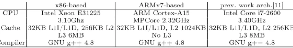
x86-based ARMv7-based prev. work arch.[11]
CPU Intel Xeon E31225 ARM Cortex-A15 Intel Core i7-2600
3.10Ghz MPCore 2.32GHz 3.40GHz
Cache 32KB L1I/L1D, 256KB L2 32KB L1I/L1D, L2 1024KB 32KB L1I/L1D, L2 256KB
L3 6MB No L3 L3 8MB
Compiler GNU g++ 4.8 GNU g++ 4.8 GNU g++ 4.8
Table 1. Performance evaluation platforms.
The platforms used for performance evaluation are shown in Table 1. Unless stated otherwise, each measure is obtained as the best of ten runs of a 10 second simulation, taking into account frame loading and result storing. SNR (Signal Noise Ratio) is set to 2.5 dB for tests with 1/5 and 1/2 rates, and to 4.0 dB for
the 5/6, 0.84, and 9/10 rate tests. Colors differentiate the codes rates of the Polar Code, point shapes differentiate decoder types (Intra-SIMD vs Inter-SIMD).
6.1 Comparison between P-EDGE and the State of the Art
���������������������������������������� ���� ���� ���� ���� ���� ���� ���� ���� � � � � �� �� �� �� �� �� �� ������������������������� ���������������������������� ��������������������������������� ���������������� �������������� ���������������� �������������� ��� ��� ��� ��� ��� ��� ���� ���� ���� � � � � �� �� �� �� �� �� �� ���������������������������� ������������������������������������� ���������������� ����������������
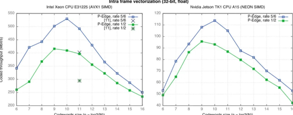
Fig. 6. Performance comparison between several code rates of 32-bit floating point decoding stages (running on the Intel R
Xeon R
CPU E31225 and, respectively, on the Nvidia R
Jetson TK1 R
CPU A15).
(N, K) Decoder Info T/P (Mb/s) Latency (µs) (16384, 14746)prev. work[11] 292 50 this work 341 43 (32768, 27568)prev. work[11] 220 125 this work 241 114 (32768, 29492)prev. work[11] 261 113 this work 293 101
Table 2. Comparing P-EDGE with a state-of-art software polar decoder, for codes of rate 0.84 and rate 0.9, using Intra-SIMD. The two cross marks show state-of-the art performance results reported in [11], for comparison.
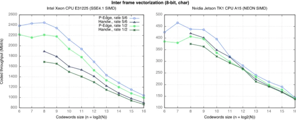
Fig. 6 shows P-EDGE intra-frame throughput on different architectures. Our generic framework performance outperforms previous work decoder results (be-tween 10% and 25% higher). This is confirmed in Tab. 2 which compares P-EDGE with the state-of-the-art result samples for some specific rates reported in [11]. The throughput of the inter-frame implementation is shown in Figure 7 for different architectures. Again, the results confirm that our generic approach overtakes handwritten code (also between 10% and 25% higher on x86).
��������������������������������������� ���� ����� ����� ����� ����� ����� ����� ����� ����� ����� � � � � �� �� �� �� �� �� �� ������������������������� ���������������������������� ����������������������������������� ���������������� ���������������� ���������������� ���������������� ���� ���� ���� ���� ���� ���� ���� ���� ���� � � � � �� �� �� �� �� �� �� ���������������������������� �������������������������������������
Fig. 7. Performance comparison between several code rates of 8-bit fixed point de-coding stages (running on the Intel R
Xeon R
CPU E31225 and, respectively, on the Nvidia R
Jetson TK1 R
CPU A15). Circles show P-EDGE results. Triangles show our former “handwritten” implementation results [8].
Decoder N = 26 N = 28 N = 210 N = 212 N = 214 N = 216 inter 32-bit, R = 1/2 1 (7) 2 (24) 7 (77) 9 (254) 19 (736) 40 (2528) inter 32-bit, R = 5/6 1 (4) 2 (19) 4 (53) 7 (167) 16 (591) 32 (1758) intra 32-bit, R = 1/2 1 (4) 3 (16) 9 (56) 8 (182) 19 (563) 38 (1947) intra 32-bit, R = 5/6 1 (3) 3 (13) 6 (38) 7 (126) 20 (392) 27 (1365) inter 8-bit, R = 1/2 1 (5) 2 (22) 7 (72) 8 (252) 17 (665) 36 (2220) inter 8-bit, R = 5/6 1 (4) 2 (18) 4 (51) 6 (191) 14 (461) 26 (1555) Table 3. Code size (in KB) of the generated decoders depending on the number of bits N per frame (code respectively compiled with AVX1 instructions for the 32-bit decoders and with SSE4.1 instructions for the 8-bit decoders). For comparison, code size without compression are shown in parentheses.
For all the test series, the bandwidth first increases with codeword size, as the tree pruning becomes increasingly more effective with larger trees. The effect is stronger for Intra-SIMD where pruning also results in removing inefficient scalar nodes. However, beyond a codeword size point which depends on the architecture and on the selected SIMD version, performance decreases again due to L1 cache misses, not only L1D but L1I as well. Indeed, decoders are generated as straight-line code (no recursive calls), with all node computations put in sequence. This improves performance for small to medium codeword size, up to the point where the compiled binary exceeds the L1I cache size. We mitigated this issue by reducing decoder binary sizes using two compression techniques: 1) in the generated code, we moved the buffer offsets from template arguments to function arguments, which enabled the compiler to factorize more function calls than before (improvement by a factor of 10), 2) we implemented a sub-tree folding algorithm in the generator, to detect multiple occurrences of a same
sub-tree and to put the corresponding code into a dedicated function (improvement
by a factor of 5 forN = 216, the compression ratio increases with the size of the
tree).
Table 3 shows the binary code size of the decoders depending on N . The
results which exceed the 32KB of the L1I cache are highlighted in bold font.
Sub-tree folding was enabled starting fromN = 212because there is an overhead
(at run-time) when using this technique. P-EDGE decoder code sizes without compression are shown in parentheses: we can observe a huge improvement, until
N = 214 the code size never exceeds the L1I cache anymore.
6.2 Exploring respective optimization impacts with P-EDGE
In this sub-section the compression techniques have been disabled.
������������������������������������������������������� �� ���� ���� ���� ���� ���� ��� ��� ��� ���� ������������������������� ���������������� ������������������������������ ��� ��� ��� ������ ��� �� ���� ����� ����� ����� ��� ��� ��� ���� ���������������� ������������������������������� ���� ���� ���� ��� ���� ���� ��� ���� ���� ���� ���� ��������
Fig. 8. Throughput depending on the different optimizations for N = 2048, for intra-frame vectorization on the left and intra-intra-frame vectorization on the right, resp. (on the Intel R
Xeon R
CPU E31225).
The tree pruning step has a dramatical effect in general. For example, the reference code for a rate of 1/2 has 2047 nodes, whereas only 291 nodes remain in the pruned version. However, the individual effect of each rewriting rule is not trivial. The plots in Figure 8 show the respective impact of several rewriting rules
(cuts, repetitions, single parity checks (SPC)), withN = 2048 and multiple code
rates, for Intra-SIMD and Inter-SIMD respectively. The purpose of the plots is to show that no single rewriting rule dominates for every code rate, and that the respective impact of each rule may vary a lot from rate to rate, making the case for the flexible, extensible architecture of P-EDGE. Indeed, P-EDGE’s rewriting rule set can also be enriched with rules for specific ranges of code rate. For instance, the rule Single Parity Check (SPC) has been applied with different level limits for 9/10 code rate, where it has a significant impact and may benefit from fine tuning.
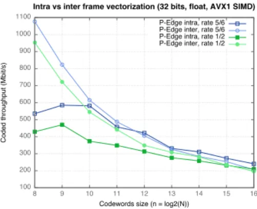
���� ���� ���� ���� ���� ���� ���� ���� ���� ����� ����� � � �� �� �� �� �� �� �� ������������������������� ���������������������������� ������������������������������������������������������������� ���������������������� ���������������������� ���������������������� ����������������������
Fig. 9. A focus on 32-bit floating point P-EDGE decoder instances performance on large codeword size, considering the decoding time only (on Intel Xeon CPU E31225).
A comparison between the performance of the different decoder instances obtained from the same code is shown in Figure 9. Only codeword sizes of more
than28 are shown, as smaller sizes are of little interest in practice. One can see
that for a given bit rate, the best version depends on the codeword size. Inter-SIMD dominates for a 1/2 rate, while Intra-Inter-SIMD dominates for a 5/6 rate on
code size larger than212. This shows the interest of having both intra-frame and
inter-frame SIMD in the same framework.
7
Conclusion and future works
In this paper, we have developed a framework that enables exploring optimiza-tions for Successive Cancellation decoders of the Polar Codes family while enforc-ing a clear separation of concerns between the generic, abstract algorithmic level and the low-level architecture dependent on building block implementations. The benefits in terms of software design and flexibility are not overshadowed by prohibitive run-time performance results. On the contrary, the use of a spe-cialized skeleton generator to produce optimized compile-time decoders enables performance levels to match, and even to exceed state of art implementations.
Future work will in priority be dedicated to a more in-depth performance analysis, for instance by applying the Roof-line model [19] or even better the Execution-Cache-Memory (ECM) model [16], would also give us much more insight about the remaining code optimization head-room, as the algorithm tend to be inherently memory bound. Finally, we intend to stress-test the genericity of our framework on other decoder variants from the Polar Codes family.
8
Acknowledgements
This study has been carried out with financial support from the French State, managed by the French National Research Agency (ANR) in the frame of the
"Investments for the future" Programme IdEx Bordeaux - CPU (ANR-10-IDEX-03-02). The authors would also like to thank Guillaume Berhault for the helpful discussions.
References
1. Alamdar-Yazdi, A., Kschischang, F.: A simplified successive-cancellation decoder for polar codes. Communications Letters, IEEE 15(12), 1378–1380 (December 2011)
2. Arikan, E.: Channel polarization: A method for constructing capacity-achieving codes for symmetric binary-input memoryless channels. Information Theory, IEEE Transactions on 55(7), 3051–3073 (2009)
3. Berrou, C., Glavieux, A., Thitimajshima, P.: Near shannon limit error-correcting coding and decoding: Turbo-codes. 1. In: Communications, 1993. ICC ’93 Geneva. Technical Program, Conference Record, IEEE International Conference on. vol. 2, pp. 1064–1070 vol.2 (May 1993)
4. Gallager, R.G.: Low-density parity-check codes (1963)
5. Giard, P., Sarkis, G., Thibeault, C., Gross, W.: Fast software polar decoders. In: Acoustics, Speech and Signal Processing (ICASSP), 2014 IEEE International Con-ference on. pp. 7555–7559 (May 2014)
6. Gottschling, P., Wise, D.S., Joshi, A.: Generic support of algorithmic and structural recursion for scientific computing. The International Journal of Parallel, Emergent and Distributed Systems (IJPEDS) 24(6), 479 – 503 (12/2009 2009), accepted 7. Le Gal, B., Leroux, C., Jego, C.: Software polar decoder on an embedded processor.
In: Proceedings of the IEEE International Workshop on Signal Processing Systems (SIPS’14). pp. 1—6. Belfast, UK (October 2014)
8. Le Gal, B., Leroux, C., Jego, C.: Multi-gb/s software decoding of polar codes. IEEE Transactions on Signal Processing 63(2), 349–359 (Jan 2015)
9. MacKay, D.J.: Good error-correcting codes based on very sparse matrices (1999) 10. Puschel, M., Moura, J., Johnson, J., Padua, D., Veloso, M., Singer, B., Xiong,
J., Franchetti, F., Gacic, A., Voronenko, Y., Chen, K., Johnson, R., Rizzolo, N.: Spiral: Code generation for dsp transforms. Proceedings of the IEEE 93(2), 232 –275 (feb 2005)
11. Sarkis, G., Giard, P., Thibeault, C., Gross, W.: Autogenerating software polar decoders. In: Signal and Information Processing (GlobalSIP), 2014 IEEE Global Conference on. pp. 6–10 (Dec 2014)
12. Sarkis, G., Giard, P., Vardy, A., Thibeault, C., Gross, W.: Fast polar decoders: Algorithm and implementation. Selected Areas in Communications, IEEE Journal on 32(5), 946–957 (May 2014)
13. Shannon, C.: A mathematical theory of communication. Bell System Technical Journal 27, 379–423, 623–656 (1948)
14. Spampinato, D.G., Püschel, M.: A basic linear algebra compiler. In: Proceed-ings of Annual IEEE/ACM International Symposium on Code Generation and Optimization. pp. 23:23–23:32. CGO ’14, ACM, New York, NY, USA (2014), http://doi.acm.org/10.1145/2544137.2544155
15. Stroustrup, B.: The C++ Programming Language. Addison-Wesley Professional, 4th edn. (2013)
16. Treibig, J., Hager, G.: Introducing a performance model for bandwidth-limited loop kernels. CoRR abs/0905.0792 (2009), http://arxiv.org/abs/0905.0792
17. Walter, J., Koch, M.: ublas, www.boost.org/libs/numeric
18. Whaley, R.C., Petitet, A., Dongarra, J.: Automated empirical optimizations of software and the atlas project 27(1-2), 3–35 (2001)
19. Williams, S., Waterman, A., Patterson, D.: Roofline: An insightful visual perfor-mance model for multicore architectures. Commun. ACM 52(4), 65–76 (Apr 2009), http://doi.acm.org/10.1145/1498765.1498785