: I
Design of Position Sensors for Subsea Oil Tools
by
David M. Micheletti
S.B. Mechanical Engineering Massachusetts Institute of Technology
SUBMITTED TO THE DEPARTMENT OF MECHANICAL ENGINEERING IN PARTIAL FULFILLMENT OF THE REQUIREMENTS FOR THE DEGREE OF
MASTER OF SCIENCE IN MECHANICAL ENGINEERING AT THE
MASSACHUSETTS INSTITUTE OF TECHNOLOGY JUNE 2003
Signature redacted
Signature of Author: _--=----_ _ _ _ _ _ _ _ _ _ _ _ _ _ _ _ _ _ _ _ _ _ _ _ Department of Mechanical Engineering
May 9,2003
Signature redacted
Certified by:
---7~"'----!:....J-.-..ol-V"l-#-' --"·-~OC""'-'--=
...-K'--a-m-a-I.:::..zY'-L~-=-~~=-e~i_'lr-.T-o-u-mi
Professor of Mechanical Engineering/ 0
~ Thesis SupervisorSignature redacted
Accepted by: _ _ _ _ _ _ _ _ _ _ _ _ _ _ _ _ -.:-~-::::::::.""Q~ ... --'-~ ...
~--===~-==---Ain A. Sonin Professor of Mechanical Engineering Chairman, Departmental Committee on Graduate Studies
MASSACHUSETIS INSTITUTE OF TECHNOLOGY
Design of Position Sensors for Subsea Oil Tools
by
David M. Micheletti
Submitted to the Department of Mechanical Engineering on May 9, 2003 in Partial Fulfillment of the Requirements for the Degree of Master of Science in
Mechanical Engineering
ABSTRACT
An existing sensor system for a subsea oil tool was evaluated in order to identify and eliminate causes of failure in the system. The existing contact switches were replaced with non-contact sensors that use reed switch technology, and the components of the system were redesigned to improve reliability by preventing ingress of hydraulic control fluid.
Prototypes of the redesigned system were built and tested to validate the most critical design points. Experimental testing concluded that the redesigned system can reliably seal out fluid and prevent electrical shorting, and that the redesigned sensors are able to operate even in areas where there is significant magnetic interference.
Thesis Supervisor: Kamal Youcef-Toumi Title: Professor of Mechanical Engineering
Acknowledgements
I owe a debt of gratitude to the many people who helped make this project a success. I would like to
thank the Subsea Group at Schlumberger for giving me the opportunity to perform this research. Alan Johnston and John Kerr generously agreed to take me on and commit the resources necessary to carry out this research. Joe Scranton, John Meijer, and Dave Mathis and others gave me valuable feedback and daily support. Academically, Kamal Youcef-Toumi has been invaluable both as my thesis advisor and throughout my three years in the Engineering Internship Program. Fred Cote and the staff of the Edgerton Center Student Shop also provided invaluable insight and advice for machining the prototypes. Finally, I would like to thank my parents and Beth for their personal support these many years.
Contents
Chapter 1: Introduction . . . . . . . 5
Chapter 2: Existing switch system . . . . . . . .. . . . 9
Chapter 3: Investigation of failures . . . . . . . 19
Chapter 4: Investigation of available sensor technologies . . . .. . . 23
Chapter 5: Revised position sensor system . . . .. . 26
Chapter 6: Implementation into the existing SenTREE 7 . . . .. . . 41
Chapter 7: Testing . . . . . . . . . . . 48
Chapter 8: Conclusions and Recommendations . . . . . 65
Chapter 1: Introduction
1.1 Background
Schlumberger's SenTREE 7 subsea completion and test tree provides an additional measure of safety to the process of offshore oil production. In deep-water well completion and testing, a floating rig is positioned hundreds or even thousands of feet directly above the well head on the sea floor. A completion and test tree is deployed inside the marine riser by a landing string, run through the blowout preventer (BOP) stack, and connected to the production tubing hanger (Christie, 2002). In this manner, the rig operator has direct access to the well. A typical floating rig is shown in figure 1.
Figure 1: A floating rig (courtesy of Schlumberger)
It is imperative that the floating rig maintains its position directly above the wellhead. Any drift off-center would create a bending moment in the riser and increase the possibility of failure. Failure of the riser would result in a major release of hazardous fluids into the environment, with severe economical and ecological consequences.
Unforeseen events like severe weather, mechanical failure, or other emergencies may cause the rig to drift off-center. When this occurs, the SenTREE 7 allows the operator to shut in the well and disconnect from the wellhead. The rig can then float freely with the riser attached to the rig. When the emergency is over or the problem is fixed, the operator may then reconnect the riser and continue operations. The setup with the riser disconnected is shown in figure 2.
Figure 2: The SenTREE 7 allows the riser to separate from the well (courtesy of Schlumberger) The SenTREE 7 is composed of four main subcomponents. There are three valves named the retainer valve, flapper valve, and ball valve, as well as a piston-actuated latch. In operation, the valves close to shut in the well, and the latch releases so that the riser may disconnect from the well. First, the ball valve is closed to stop the flow and shut in the well. Then, the flapper valve closes to provide a secondary seal between the wellbore and the environment. Next, the retainer valve is closed so that fluid in the riser does not spill out upon disconnect. Finally, the latch mechanism is released so that the separation can occur.
When it is time to reconnect, the process is reversed. The latch reconnects. Then, the retainer opens. Then, the flapper and ball valves open, and the well can flow again. Figure 3 shows the SenTREE 7 in both the open and disconnected states.
RE-T AINER LATCH FLAPPER BALL
VALVE VALVE VALVE
--- -- - -- -- --- -- -- --- -- -- - -- --- -- -- - . .. .. ... - - --- -- -- --- -- -- --- -- --K A --- --- -- -- --- --
--Figure3: The SenTREE 7 shuts in the well and disconnects 1.2 The Problem
In order for a successful shut in and disconnect to occur, all three valves must close completely and the latch must release. It is highly desirable for the operator to know the position of the valves and latch mechanisms. A position indicating system already exists in the SenTREE
7, but it has proven to be unreliable. The project is to determine the causes of failure in the
existing system and revise or redesign the system to improve reliability.
1.3 Importance of Problem
The development of a reliable position-indicating system is extremely important. It is imperative that the operator be able to confirm that the mechanisms are operating correctly. A failure in one or more of the subsystems could have severe consequences. For example, if the retainer valve does not close entirely and the system disconnects, the borehole fluids in the riser
r
'=az
--- ... ---F7 7 ,--
---could spill into the ocean. If the latch does not unlock, the operator would overpull the riser and damage it. A failure in the ball valve or flapper valve would leave the system with only one barrier between the borehole fluids and the environment. Failure of both the flapper and ball valve would expose the environment to the open borehole, with catastrophic results.
1.4 What Others Have done
Currently, there are two methods being used to determine the positions of the switches and the latch. The first method is the indirect estimation of valve position through measurement of hydraulic fluid. Because the valves and latch are actuated with hydraulic pistons of known geometry, there exist known relationships between the volume of control fluid inserted into each valve and the position of the corresponding piston. Therefore, the volume of control fluid applied can be measured to determine piston position and, indirectly, valve position. While this is a reliable method of determining valve position, the valve position cannot be measured in real time using this method.
The second method currently in use is an electrical contact switch system. A contact switch is installed in each subsystem. In operation, a hydraulic piston moves to actuate the valve or latch. When the piston comes to the end of its stroke, the valve closes and the piston contacts the sensor. An electrical signal is then sent uphole to the operator. An electrical sensor system has significant advantages over hydraulic measurement because the operator receives real-time information about valve position. Additionally, the electrical sensor package is beneficial because it can be used as a redundant method to confirm measurements of the hydraulic fluid. However, the existing sensor system has severe reliability issues, which will be discussed in
1.5 Technical issues to be addressed.
The sensor system must be revised to improve reliability and prevent electrical shorting, and there are many technical challenges that must be addressed. The system must operate in extreme environments, with pressures of up to 5000 psi, and temperatures up to 300 degrees F while immersed in the control fluid. Another important engineering constraint is the limitation of available electrical lines. The tool has only five electrical ports for down hole electrical wiring, and only one electrical conductor can be installed in each port. These ports are used to power down hole gauges and sensors, as well as any client-specific equipment. The revised position indicating system must give position of all four subsystems while using a minimum of electrical lines. Additionally, the revised system should be able to transmit the switch position information over 5,000 feet of wire with no additional amplification. Finally, as in most engineering applications, cost also plays a factor. The revised switch system must be economically feasible. The fabrication cost must be reasonable, and the revised design must be able to be applied to the existing tool with a minimum of re-machining.
1.6 Method for solving the problem
In order to determine the best way to improve reliability of the system, investigations were conducted into the nature of the failures and the possible causes of those failures. Upon determining the most likely reasons for system failure, top-level functional requirements were specified so that the revised design eliminates the failure modes. The different types of available sensing techniques were then identified, and methods were evaluated for incorporating those available technologies into the SenTREE 7. Finally, an actuation method was selected and the system was redesigned for improved reliability.
Chapter 2: Existing switch system
2.1 Introduction
In 1999, the SenTREE 7 was retrofitted with a system of contact-based electrical position sensors. The system was designed to give the operator positive confirmation that the valves and latch are closed while using a minimum of control lines. The system consists of four contact-based position sensors, with one sensor located in each of the four modules.
2.2 Theory of operation
Each position sensor consists of a Normally Open mechanical switch, wired in parallel with a resistor. The sensor gives a binary signal, which is indicated by measuring the resistance across the sensor. When the switch is open, current flows only through the resistor. The operator reads the sensor resistance as being equal to the resistor. When the switch is closed, the resistor is bypassed, and the total resistance in the sensor drops to zero. An electrical diagram of the existing switch is shown in figure 4:
R I
Figure 4: The existing sensor features a resistor and a switch in parallel
The biggest advantage of this design is that, unlike many sensors that require amplification and multiple electrical lines, this sensor can give a clear signal using only one electrical line and with no additional amplification. Additionally, this sensor system is expandable. Because the resistor is wired in parallel with the switch, electrical continuity in the system is maintained regardless of switch position. Furthermore, due to the additive nature of
resistors in series, multiple sensors may be connected in series on a single line, as shown in figure 5:
R1 R2 R3 R4
Figure 5: Sensors may be wired in series using a single control line
The total resistance in the system is then the sum of the resistances across each sensor. Each of the four sensors has two positions. Therefore, there are 16 possible combinations of switch positions. Thus, the system can have a maximum of 16 unique resistances. The maximum resistance in the system is RI + R2 + R3 + R4, which occurs when all switches are electrically open. The minimum resistance in the system is zero, which occurs when all of the switches are closed. By carefully selecting a different resistor for each switch, the system can be made to yield a different total resistance for each combination of switch positions, as shown in table 1:
Retainer Latch Flapper iBall IR tot
R1=25 R2=50 R3=100 R4=200
Closed Closed Closed Closed 0
Open Closed Closed Closed 25
Closed Open Closed Closed 50
Open Open Closed Closed 75
Closed Closed Open Closed 100
Open Closed Open Closed 125
Closed Open Open Closed 150
Open Open Open Closed 175
Closed Closed Closed Open 200
Open Closed Closed Open 225
Closed Open Closed Open 250
Open Open Closed Open 275
Closed Closed Open Open 300
Open Closed Open Open 325
Closed Open Open Open 350
Open Open Open Open 375
Table 1: System resistance for all combinations of valve positions
An operator may refer to this table to ascertain the positions of the modules. For example, if the operator measures a resistance of 250 Q, he knows that the retainer and flapper valves are closed, but the latch and ball valve are open.
2.3 Hardware
The SenTREE 7 is designed to be modular. The valves and latch are built as self-contained and independent modules. These modules are built and completed separately. The modules are then shipped to the rig, where they are attached to create an entire SenTREE 7 system. The components of the position sensing system were designed to maintain this modularity. The position sensing system for each of the valve subsystems is completely contained by that subsystem.
The sensing system in each of the modules contains a sensor, electrical conducting rods, and wet mate connectors. The sensor is installed in the valve or latch housing to give information regarding piston position. The conducting rods carry the electrical signal to the ends
of the module. The wet mate connectors seal in the control fluid and prevent the ingress of contaminants, as well as providing an electrical connection to the rest of the SenTREE 7.
In the ball valve, retainer valve, and latch, a hydraulic piston directly triggers the sensor. As the valve is closed, the piston deflects the cantilevered beam and closes the switch. An example of the piston actuation of the sensor is shown in figure 6:
Sensor
Piston
Connector
Rods
Figure 6: A piston actuates the contact sensor.
For the flapper valve, it was not possible to have the piston directly actuate the sensor. Instead, a rod that is mounted radially to the piston actuates the flapper valve position sensor. The actuation of the flapper valve is shown in figure 7:
Rods
Sensor
Piston
Piston Rod
Figure 7: A rod mounted to the piston actuates the flapper valve sensor
The position sensing system for the flapper valve uses conducting rods and wet mate connectors like the other valves.
2.3.1 Contact-based position sensors
Because the geometric constraints differ greatly between the modules, two different sensors are used in the system. The first sensor is used in the retainer valve, latch, and ball valve. This sensor features two leads, which are connected by a resistor. The contact mechanism is a cantilevered beam design. When the switch is open, the end of the beam is a small distance from the contact. When the piston collides with the switch, the beam deflects and makes a connection with the contact. A rubber pad attached to the beam compensates for machining tolerances and prevents crushing of the sensor. The sensor is shown in figure 8:
Figure 8: The first sensor has a cantilevered beam design
Due to geometric constraints, the sensor in the flapper valve is different from the other sensors. There was not sufficient space inside the flapper housing to install a sensor that is actuated directly by the hydraulic piston. Rather, a rod is mounted so that it extends radially from the piston, and this rod actuates the sensor. To accommodate this actuation method, the sensor in the flapper valve features a horizontally mounted contact switch. In this sensor, the cantilevered beam is replaced by a commercially available Normally Open contact switch. In this design, the switch is the Microswitch 311SM43-T, manufactured by Honeywell Inc. (Freeport, IL), shown in figure 9:
Honeywell Switch PEEK
Housing
2.3.2 Conducting rods
The switches are interconnected using a series of conductive copper rods. In general, it is preferable to use insulated wire rather than conducting rods because issues of insulation and continuity are much simpler. For this application, however, conductive rods have two distinct advantages. The first advantage is ease of installation. The rods can thread into the wet mate connectors and then be pushed through the electrical port and inserted into the switch. The second advantage is that the rods provide structural support to the switch. By threading or stabbing into the sensor, the rod constrains the sensor and prevents it from falling out or rotating once it is installed. An example of the rods is shown in figure 10:
Figure 10: The copper rod has a pin on one end and a #8-32 thread on the other
Because the pistons that contact the switches are hydraulically actuated, the sensor system must be immersed in the hydraulic control fluid. The system was designed for use with non-conductive control fluids; so electrical shorting was not a significant concern. To prevent the rods from contacting the valve housing and shorting the system, the rods are wrapped with shrink tubing.
2.3.3 Wet mate connectors
The wet mate connectors serve two purposes. First, the connectors provide electrical continuity between components that are inside the valve housing and components that are outside the housing. Second, the wet mate connectors maintain a seal between the valve housing and the environment. There are two types of wet mate connectors: male and female. The connectors both have double o-ring seals and a copper tip that a conducting rod can thread into. The wet mate connectors are shown in figures 11 and 12:
Inconel Body
PEEK
Insulation
Copper
Conductor
Figure 11: The male wet mate connector
PEEK
Inconel Body
Insulation
Copper
Conductor
Figure 12: The female wet mate connector
Although the connectors have electrical components that are exposed to the control fluid, this was not a concern because the system was designed for use with nonconductive control fluid. 2.4 Failures in the existing sensor system
The rod and sensor system has severe reliability issues that were difficult to address or remedy. The system repeatedly failed in the field. The most common failure mode was that the system electrically shorted to ground and therefore gave no useable information about the valve positions. However, these failures were intermittent and unrepeatable. Certain sensor subsystems would work on land but not on the rig. Later on, some of the systems that had failed would mysteriously work again. Sometimes the sensors worked when the SenTREE 7 was laid
on the rig floor but failed when it was stood upright. Finally, operators in the field sometimes reported measuring negative resistance during testing of the system. These failures were investigated in order to identify aspects of the system that could be improved.
2.5 Conclusion
The design of the existing sensor system was introduced. The sensor system's theory of operation and physical components were described. The benefits and problems with this design were also addressed.
Chapter 3: Investigation of failures
3.1 Introduction
The first task that was undertaken was to determine the cause of the shorting in the sensor system. At first inspection, there was no apparent reason for the electrical failure. The electrical system, immersed in a nonconductive fluid should not cause the system to short. Furthermore, nearly all electrical components were insulated with either molded PEEK or rubber tubing,
making shorting due to physical contact an unlikely culprit. To determine the causes of system failure, both the mechanical and electrical aspects of the system were investigated. It is important to note that it is possible that the system fails due a single cause or a combination of several causes.
3.2 Failure due to mechanical contact
Initially, mechnical malfunction seemed to be the most probable cause of system failure. Three possible mechanical malfunctions were identified that would result in system failure. Investigations were conducted to evaluate the likelihood of failure due to inadvertent actuation, damage to system, and contact between the electricals and the tool housing.
The first possibility was that the sensor system was not failing intrinsically, but that it was being actuated inadvertently. For example, if a piece of debris were to enter the system, it could depress the sensor and trigger it, resulting in a false reading. Similarly, the presence of metal shavings or filings could become lodged between the contacts, also resulting in a false reading. While steps are taken to ensure cleanliness of the tool and absence of metal shavings, it cannot be known if these are followed all of the time. After investigation, findings were inconclusive and the hypothesis that the system fails due to inadvertent actuation could neither be confirmed nor eliminated.
The next cause of failure that was investigated was mechanical damage to the system. Earlier versions of the sensor had been crushed or deformed during operation. Although this issue had been addressed, it was possible that somehow a component of the system was being damaged, resulting in a false indication. Reports from the field were collected, stating the nature of the failures and any unusual circumstances surrounding the failure. While some of the systems that had failed did have damaged components, many of them did not. Thus, it was concluded that although mechanical damage may be a cause of failure, it is not the only cause.
Finally, the issue of possible physical contact between an electrical component and the tool housing was investigated. Specifically, the possibility of the rod contacting the electrical port was investigated. Inspection of the geometries of the latch and the different valves indicated that the rods are heavily constrained and are not free to touch the port. Also, because the rods are insulated with rubber tubing, contact with the housing would not result in shorting. It was then concluded that the most likely mechanical cause of failure was debris in the system.
3.3 Failure due to Electrical Shorting in control fluid
Purely electrical causes of system failure were then investigated. At first it was not possible to identify any phenomena that would cause the sensor system to short. Because the control fluid is nonconductive, it should not matter that the electrical components are not sealed. Additionally, the sensor system is low power, so it was not likely that arcing would occur.
While it was possible that debris was the sole cause of shorting in the system, it did not explain why the operator measured negative resistance across the system. The initial assumptions were re-examined and the role of the control fluid was reevaluated. Two types of control fluid were tested for conductivity, with surprising results. It was discovered that the first control fluid is somewhat conductive, and the second is nearly as conductive as seawater. Upon
further investigation, it was also revealed that the conductivity of the control fluid could vary greatly with each installation. Contamination has a major impact on fluid conductivity. A 2% contamination of control fluid by seawater triples the conductivity, and a 5% contamination increases it by a factor of 20. Schlumberger specifies Oceanic HW 525 as the recommended hydraulic control fluid for the SenTREE 7. However, client companies may select a different control fluid, which may or may not be compatible with the sensor system.
3.4 Findings
Investigation into the nature of failure of the sensor system revealed that the conductivity of the control fluid has the biggest impact on system reliability. The control fluid is in fact conductive, and therefore the system can short when it is immersed in the fluid. In regards to the negative resistance, it may be that the operator measured negative resistance in the system due to current generation caused by galvanic corrosion in the tool. Furthermore, it was noted that testing of the sensor system is typically done using tap water rather than control fluid. This method for testing is not appropriate because the control fluid may be significantly more conductive than tap water.
There were two primary types of shorting possible in the system. The first is shorting between the contact points in the switch. The contacts are 0.020" apart, and when immersed in a conductive fluid, the effect is similar to adding another resistor in parallel to the switch. The resulting electrical system is shown in figure 13:
R5
R5
R5
R5
R1
R2
P3
PR4
Figure 13: The sensor system in a conductive control fluid
In figure 13, it is estimated that the extra resistor added in parallel is the same for all four switches because resistance in a fluid depends on fluid conductivity, area, and distance. All four switches have approximately the same distance between contacts, and it can be assumed that the fluid in each module is the same. When the fluid has a very low conductivity, R5 is very high, and the total resistance is nearly equal to the nominal resistance in each sensor. When the fluid has a very high conductivity, R5 is low and the resistance across each sensor is always near zero.
The second possible location of arcing is between the rods and the housing. While the rubber shrink tubing would prevent physical contact between the copper of the rod and the housing, it cannot isolate the conductive metal from the control fluid (nor was it designed to). There are several points where shorting could occur. The most likely places are at the either end of a rod, where the rubber tubing ends.
3.5 Conclusion
The causes of system failure were investigated, and it was determined that the most likely cause of failure in the sensor system is due to the conductivity of the control fluid. The control fluids that are used in the SenTREE 7 are conductive, and the exposed electrical components are likely to short when they are submerged in the fluid. The system must be redesigned to prevent the ingress of control fluid into the sensor system.
Chapter 4: Investigation of available sensor technologies
4.1 Introduction
After it was decided to redesign the sensors to improve reliability, investigations were conducted to identify the different types of position-sensing techniques and devices that could be used in place of a contact switch while maintaining the profile. In addition to contact switch, other types of sensors were evaluated, including piezoelectric sensors, cantilevered beams with strain gauges, and string potentiometers, as well as noncontact sensors.
4.2 Piezoelectrics
Piezoelectric materials are materials whose physical and electrical properties are coupled.
A piezoelectric material will physically deform when a voltage is passed through it. Conversely,
the material will emit a voltage when it is physically deformed. A position sensor could be made from this material. A small, cantilevered beam made of piezoelectric material could be installed with the free end of the beam placed in the path of the piston. When the valve is closed and the piston comes full-stroke, it would contact the piezoelectric beam, thereby creating a voltage
spike that could be read by the operator at the surface.
The benefit of this idea is that the electricals could be potted with only the piezoelectric beam exposed. Then, the piezoelectric material could be coated with an epoxy or other insulator,
thereby completely electrically isolating the sensor from the environment.
The drawback of this concept is that the signal is transient. The signal generated when the piston closes is a function only of the change in stress in the beam. When the piston closes, the operator would read a spike in the voltage, and then the signal would return to its initial state (zero). After the initial contact, the sensor would no longer give any information about the
position of the valve. If the operator somehow had a malfunction and did not see the spike, there is no way for him to determine the position of the valve.
4.3 Strain gages
A strain gage sensor could be used to give a signal when the piston closes. A small,
cantilevered beam could be constructed and installed with the free end in the path of the piston. The cantilevered beam would be equipped with one or more strain gauges. When the piston comes full-stroke to close the valve, it would contact the beam, causing it to deflect and deform the strain gauges. This deformation would cause a change in the resistance of the gauges, which
could be observed at the surface.
One benefit of this design is that the electricals could all be easily isolated from the environment. Also, the signal that the operator receives is dependent only on the deflection of the beam. Therefore, if a malfunction or other unforeseen event causes the operator to not witness the initial closing of the valve, the signal will still give definitive indication that the beam is being deflected and therefore the piston is at full-stroke.
The biggest drawback of this design is the number of electrical lines necessary. Strain gages typically require amplification by a wheatstone bridge or other means. Also, because the resistance does not change by discrete values, it is not possible to connect sensors in series. 4.4 String potentiometer
A string potentiometer is used in the auto industry to measure the travel of an
automobile's suspension during handling tests. It consists of a potentiometer and a spring-loaded spool. Wire from the spool is attached to an object that is to be measured. As the object moves, the spool unwinds and turns the potentiometer. The linear travel of the object can then be described by the change in resistance of the device.
The benefit of using a string potentiometer is that it gives information on valve position throughout a large range of travel. The operator at the surface would be able to see not only when the valve is open or closed, but also intermediate positions.
The drawback of this design is that the motion of the spool and the immersion in a conductive control fluid implies that a string potentiometer that could be used in this application would require a series of dynamic seals and complicated waterproofing. Also, this would most likely require multiple control lines, as well as downhole amplification. Furthermore, commercially available devices would not fit within the geometric constraints.
4.5 Other sensing mechanisms
Several other sensing techniques were also investigated, including Linear Variable Differential Transformers (LVDTs) and noncontact sensors like sonic transducer, eddy current sensors, and Hall effect switches. These all proved to be impractical because they require too many control lines.
4.6 Conclusion
Several different commercially-available sensing technologies were evaluated in order to identify a sensing scheme that would be more conducive to the downhole environments. The available technologies cannot be easily incorporated into the existing SenTREE 7 due to the restictrictive geometries and lack of available electrical control line.
Chapter
5:
Revised position sensor system
5.1 Introduction
The position sensor system was redesigned to improve reliability while satisfying the constraints outlined in section 1.5. The revised position sensor system includes many improvements, including the development of non-contact position sensors, robustly insulated conducting rods with o-ring seals, and insulated wet-mate connectors.
5.2 Sensor Design
Initially, a significant amount of effort was devoted to developing a waterproof, pressure-compensated contact switch sensor. However, it was concluded that due to the restrictive geometries in the tool, a waterproof contact switch is an impractical solution. Purely non-contact solutions were then re-investigated, and it was determined that non-contact sensors are impractical because they require either multiple control lines or amplification. Finally, it was determined that a sensor based on reed switch technology would satisfy the performance requirements and fit within the geometric constraints.
New position sensors that incorporate reed switch technology were designed to replace the existing contact switches. Because the revised sensors do not require physical contact, they have no external moving parts. The entire sensors may therefore be sealed from the environment without requiring pressure compensation or dynamic sealing. Also, because the piston does not physically contact the sensor, the sensor will not be damaged due to normal operation of the valves.
5.3 Reed switch technology
A reed switch has properties of both contact and non-contact switches. Essentially, a
that is filled with an inert gas. Inside this tube are two ferrous strips, or reeds. In a normally open (N/O) switch, the reeds are physically separated in the absence of a magnetic field. When a magnetic field is applied in the correct orientation, the reeds become oppositely polarized and attract each other, creating an electrical connection. When the magnetic field is removed, the reeds separate and the electrical connection is broken, as shown in figure 14:
N
Figure 14: The presence of a magnetic field causes a reed switch to close
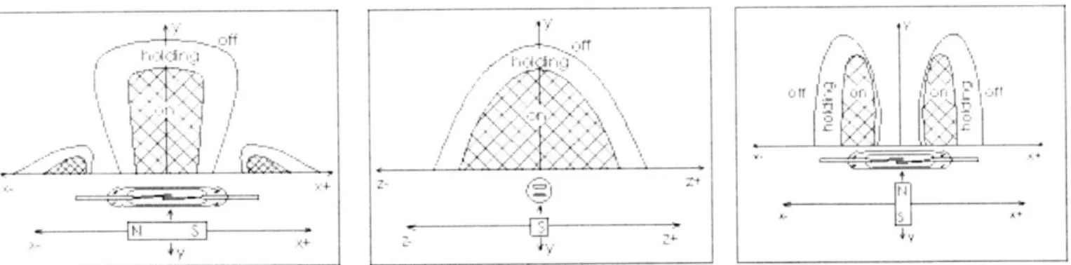
The reed switch is actuated by a permanent magnet only under specific conditions. There are three main factors that determine whether a reed switch triggers. The strength of the magnet, position of the magnet, and orientation of the magnetic field all determine the actuation of the switch. In order to trigger the switch, either the two reeds must become oppositely polarized, or only one reed must be magnetized while the other reed remains unpolarized. The conditions under which the reed switch closes is shown in figure 15:
as,
Figure 15: Operating ranges for reed switches (Crydom Magnetics, 2003)
As shown in figure 15, the magnet must have certain orientations and positions in order to trigger the switch. The switch closes when the magnet is within the "on" region, and it remains closed
-iIi.
tA
C1 ~ ~ '
while the magnet is within the "on" or "holding" regions. The switch opens again when the magnet moves out of these regions.
5.4 Selection of reed switch
After deciding to develop a sensor using reed switch technology, the specific reed switch was selected for this application. There were several considerations in selecting a particular switch. In order to fit within the geometric constraints, the glass tube of the reed switch must be
0.75" in length or less. The reed switch must also have a maximum operating temperature of
300 F (149 C). Additionally, the switch must also be able to carry sufficient current and voltage
so that a signal can be read at the surface. For this application, the reed switch that was selected was the Tiny Size Normally Open switch #TRA294G, manufactured by Crydom Magnetics Ltd. (San Diego, CA). The TRA294G was chosen because it is the smallest commercially available reed switch that meets these requirements. This switch has a glass length of 14.1 mm (.555 in), and a maximum operating temperature of 150 C. Additionally, the switch can carry 1.0 amperes of current and 150 volts. Product life of the switch is also important, and this switch has a lifetime of over 100,000 cycles. This reed switch meets all geometric and environmental requirements, and thus it was selected for use in all of the sensors.
5.5 Design of sensor bodies
Next, the sensor bodies were designed to incorporate the reed switches. The new sensor bodies were designed with several considerations in mind, including ease of installation, compatibility with existing tool geometry, reliability, and manufacturability. Three different sensors were designed for the system.
The first sensor was designed for the retainer valve and ball valve. The sensor design is shown in figure 16:
0
Figure 16: The non-contact position sensor for the ball and retainer valves.
The design of the revised sensor body preserves the most critical geometries of the original sensor, and therefore the revised sensor may be inserted into the existing ball and retainer valves without any additional machining. However, despite the geometrical similarities, the revised sensor is quite different from its predecessor. The contact mechanism was replaced with the reed switch, which is inserted into the sensor body by way of a hole drilled into the top of the sensor body. The sensor body has a notch milled into it that exposes the electrical conductors so that the resistor can be installed. The revised sensor also has flat surfaces milled into the area where the sensor and rod interface. These flats are used to facilitate o-ring sealing with the rods, as will be discussed in section 5.2.
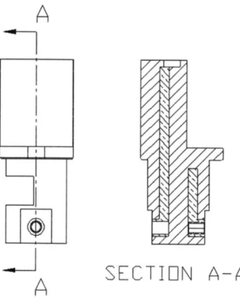
Due to the small size of the sensors, the placement of the electrical components inside the sensors was critical. Because the reed switch is longer than the diameter of the sensor, the reed switch must be installed vertically. The reed switch is installed off-center in the sensor so that it fits into the sensor along with the other electrical components. The position of the reed switch inside the sensor is depicted in figure 17:
A
SECTION A-A
Figure 17: The reed switch is installed off of the central axis
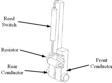
The sensor's internal conductors are made of Beryllium Copper, which was selected for its high strength and high maximum temperature. The conductors are actually fairly simple in geometry. The conductors feature square bars with holes drilled in to them for inserting the rods. The conductor in the front of the sensor is .500" in length, and the rear conductor is 1.250" in length. The reed switch is soldered between the conductors, and a resistor is soldered in parallel. The sensors interior electricals are shown in figure 18:
Reed Switch Resistor Front Rear Conductor Conductor
Figure 18: The ball valve sensor electrical design
In this sensor design, the Beryllium Copper conductors are molded into the PEEK, and the resistor and reed switch are installed after the sensor body is manufactured.
Once the resistor and reed switch are installed into the sensor body, the sensor must be insulated to protect the reed switch and prevent shorting in the control fluid. This may be accomplished by potting the sensor electricals with a marine epoxy. The epoxy coats the electictricals and hardens to protect the reed switch. Two sections must be potted: the area around the resistor and the area around the reed switch. The sensor with potting is shown in figure 19:
Figure 19: The ball valve sensor is potted to prevent shorting in the control fluid
The second sensor was designed for the Latch. It is identical to the Ball Valve sensor with one minor exception. In the latch sensor, the front conductor is tapped with a #2-56 thread. This tapped hole allows the latch rod to thread into the sensor in order to compress the o-ring and create that seal. A cross-section of the latch sensor is shown in figure 20:
SECTION A-A
A
Figure 20: The latch sensor has a tapped electrical port for o-ring sealing.
The third sensor was designed for the flapper valve. This sensor design is similar in principle to the other two sensors, but it is significantly different physically. In order to fit in the flapper valve, the sensor must be less tall than the other sensors. Because of this restriction, there is not enough space to install the reed switch vertically like in the other sensors. An L-shaped sensor was designed, and the reed switch is installed horizontally into this sensor. Like in the ball valve sensor, the flapper valve sensor has a notch milled into it in order to install the resistor. The sensor also has a hole on the top of the sensor and a hole on the back of the sensor to solder the reed switch. The flapper valve sensor is shown in figures 21 and 22:
Figure 21: The flapper valve position sensor
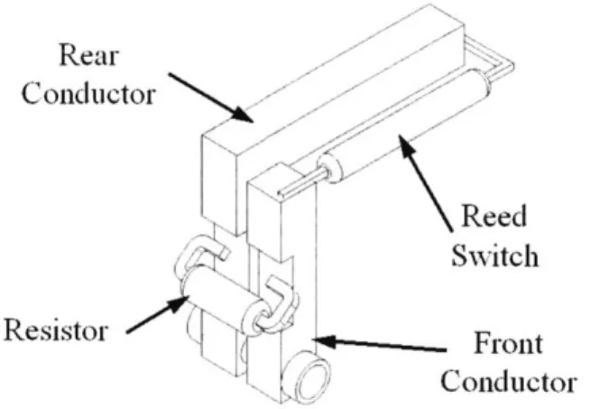
Figure 22: A milled pocket in the rear of the sensor facilitates installation of the reed switch Inside the sensor, two Beryllium Copper conductors provide the electrical connection. The front conductor is nearly identical to the front conductor of the ball valve sensor. The rear conductor is L-shaped so that the reed switch can be easily installed into the sensor. Like in the other sensors, a resistor is wired in parallel with the reed switch. The sensor's electricals are shown in figure 23:
Rear Conductor Reed Switch Resistor Front Conductor Figure 23: The flapper valve sensor electrical design
After installing the resistor and reed switch into the sensor, the sensor is potted to keep out the control fluid and protect the reed switch. The sensor has two sections that must be potted: the area around the resistor, and the area around the reed switch. The potted flapper valve sensor is shown in figure 24:
Epoxy
Figure 24: The flapper valve sensor is potted to prevent shorting in the control fluid
5.6 Rod Design
5.6.1 Design revisions
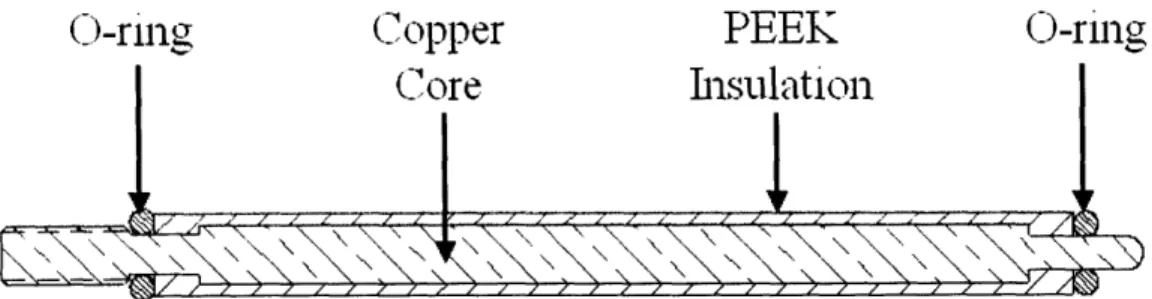
The rods were redesigned for improved reliability. The redesigned rods all include a conducting core with robust insulation and seals at interfaces to prevent electrical shorting in the control fluid. One of the revised rods is shown below in figure 25:
(1)-ring
Copper
PEEK
0-ring
Core
Insulation
Figure 25: The revised rods feature PEEK insulation and o-ring sealing
The revised rods are insulated with injection molded PEEK. PEEK was selected for its insulating properties, mechanical strength, ability to withstand high temperatures, and resistance to chemical attack. The PEEK is injection molded so that it reliably bonds to the conducting core. Also, by using injection molding, the PEEK insulation can be made thick enough to withstand accidental damage during insulation and also provide a shoulder against which the o-rings seal.
While the reliability of the conducting rods is greatly improved by robustly insulating the rods, it is further improved by completely sealing the control fluid from the system. The revised rod has o-rings at either end. When the rod is installed, the o-rings at either end of the rod are compressed and a seal is created. For the o-ring material, I selected a 90 durometer Viton. This polymer is widely used in the industry because of its high operating temperature and chemical compatibility with the hydraulic fluids.
To create the o-ring seals, the rods either stab or thread into another component. Because of the restrictive geometry in the system, it was not possible to include a gland profile for the o-ring to sit inside. Instead, I designed the rods to incorporate "crush sealing" of the o-o-rings. This sealing method creates a seal between two flat surfaces by compressing the o-ring approximately
25% or more. The o-ring is crushed between the two surfaces, and a seal is created. The benefit of this design is that an o-ring seal can be made in a small space. The largest drawback of this
sealing method is that because the o-ring is crushed and plastically deformed, it cannot be reused. The o-rings must be replaced each time that the rod is uninstalled. This is an acceptable price because the o-rings are very inexpensive and changing the o-rings on the rods is a simple task.
The conducting core of each rod is machined from Beryllium Copper rod stock. Several of the rods must be threaded in order to provide the compressive force necessary to create the o-ring seal. The high strength of Beryllium Copper allows these threaded rods to seal with a minimum rod size. Additionally, high melting point is very important because PEEK melts near
600 F, and therefore any material that has PEEK molded onto it must withstand those
temperatures. The rods for the ball/retainer valves, flapper valve, and latch were redesigned to incorporate these improvements.
5.6.2 Ball/retainer valve rods
The rods for the ball valve were redesigned to incorporate the improved insulation and sealing while maintaining compatibility with the existing hardware. The upper and lower rods are similar to the rod depicted in figure 26. They both have a pin on one end that stabs into the sensor and a #8-32 thread on the other side that threads into the wet mate connector. The upper and lower rods differ only in length: the upper rod is approximately 5 inches, while the lower rod is over 20 inches long. The installed ball valve rods are shown in figure 26:
Figure 26: Insulated rods installed in the ball valve
5.6.3 Flapper Valve rods
The flapper rods were redesigned to incorporate the insulating and sealing improvements. Like the rods in the ball and retainer valves, the flapper valve rods feature PEEK insulation, o-ring seals, and a threaded end for assembly with the wet mate connectors.
5.6.4 Latch rods
The latch presented a particularly difficult challenge because the sensor is not aligned with the electrical port. Three rods are needed to connect the wet mate connector to the sensor.
A connector is inserted into the outer conducting rod, which threads into the jumper rod. The
jumper rod threads into the inner conducting rod, which threads into the sensor. The assembled latch sensor system is shown in figure 27:
Inner Conducting] Rod JuOoper Rod Outer Conducting Rod
Figure 27: Latch rods are threaded together to seal the o-rings
The conducting pins of the rods are threaded in order to provide the compressive force necessary to create the ring sealing. The rods also have tapped holes in their sides, as well as flats for o-ring sealing.
5.6.5 Coated rods rather than injection molded rods
The use of injection-molded PEEK will result in improved reliability of the system; however, it is also very expensive. The injection molded rods each cost several hundred dollars, in addition to a tooling charge. Manufacturing the rods requires fabrication of seven high-temperature molds at a cost of approximately $14,000. Although this is not prohibitively expensive, it was important to also investigate more economical methods for insulating the rods. The most promising method for reliably insulating the rods without using injection molding is to coat the rods instead. Technology is being developed whereby PEEK can be applied as a spray-on coating rather than molded spray-on. The biggest advantages of PEEK coating is that there is no mold cost, and items can be coated in batch sizes of one, if desired.
There are also disadvantages to PEEK coating. While this may some day replace molding, the technology is still being refined, and it is not yet ready for commercial application. Also, the coating may be applied only 0.020" thick, so more metal must be used in each rod, and it is less resistant to accidental damage. The inner latch connecting rod requires over 100% more copper if the rod is coated rather than injection molded, and the insulation is less than half as thick. A comparison of the inner connecting rods is shown in figure 28:
Injection Moldedi Rodl
PEEK
Copper
I
nsulo -tion CoreCoated
Rod
Figure 28: A coated rod requires more copper and has less insulation than a molded rod After receiving a quote from Southwest Impreglon for coating the rods, it became apparent that the cost of purchasing rods and then coating them was roughly equal to the cost of the injection molded rods. The price of the two options then differs only by the mold cost. When one considers the cost of the components for the revised system and the man-hours involved, the mold cost is a small percentage of the total cost. It was then decided that the improved reliability and minimization of copper in the rods is worth the cost of the molds. Therefore, it is believed that injection molded rods is the best option to pursue.
5.7 Connector Design
The wet mate connectors were revised to eliminate exposure to the control fluid and to facilitate o-ring sealing. The PEEK insulation in the male and female connectors is extended so
that the copper conductor is sealed from the control fluid. In addition to covering the conductor, the PEEK also provides a shoulder for the o-rings to crush onto. The revised connectors are shown in figures 29 and 30:
Shoulder for
(-ring sealing
PEEK
Insulation
Figure 29: The revised male wet stab with PEEK insulation
Shoulder for C-ring sealing
PEEK Insulation
Figure 30: The revised female wet stab with PEEK insulation
5.8 Conclusion
The individual components of the sensor system were redesigned to improve reliability. The contact sensors were replaced with non-contact reed switches and encapsulated in PEEK. The rods were redesigned to incorporate PEEK insulation and o-ring sealing. The connectors were redesigned to insulate the electrical conductors and facilitate sealing with the rods.
Chapter 6: Implementation into the existing SenTREE 7
6.1 Introduction
In order to implement the revised position sensing system, some components of the SenTREE 7 must be modified. As discussed earlier, a reed sensor is activated by the presence of a magnetic field. For this application, it was clear that the best way to supply this magnetic field is with a permanent magnet. Custom magnets were designed to fit in the unusual geometries of the SenTREE 7 modules. The pistons in each valve were then modified to incorporate the custom magnets.
6.2 Sensor implementation for latch
To actuate the latch sensor, a magnet must be mounted onto the latch piston. A magnet was designed to provide the necessary magnetic field while fitting within the geometric constraints. The magnet has a slight curvature so that it fits inside the piston housing. The
magnet is 1" X " X ", and it is shown in figure 31:
N
S
Figure 31: The latch magnet
Referring to figure 31, the magnet is polarized such that the poles are at the top and bottom of the magnet. The magnet is made of Samarium Cobalt, and it is coated with PEEK to prevent
chemical interaction with the control fluid. The PEEK coating will not affect the magnetic fields of the permanent magnet because PEEK is non-magnetic, and it is applied as a thin layer. The specific magnetic properties were designed by Dexter Magnetics (Chicago, IL).
The latch piston requires minimal modification in order for the latch magnet to be mounted to the piston. A simple pocket is milled into the face of the piston, and the magnet is installed into this pocket. The piston with magnet is shown in figure 32:
Magnet
Latch
Piston
Figure 32: The revised latch piston with magnet for sensor actuation
6.3 Sensor implementation for the ball and retainer valves
Implementation of the sensor system in the ball and retainer valves is significantly more complicated than for the latch. Like in the latch, the sensor is actuated by a magnet that is mounted to the piston. However, unlike the latch, the ball valve piston is not constrained from rotating in the housing. Because the piston is free to spin, it is not possible to install a simple magnet onto the piston in such a way that the magnet is always aligned with the sensor. Also,
due to the restrictive geometry of the valve, it was not possible to add a mechanism that would constrain the orientation of the piston. A magnet and piston assembly was designed such that the
orientation of the piston does not affect sensor operation.
In order to ensure that the magnet is always aligned with the sensor, a ring-shaped magnet was designed to be installed on the ball valve piston. The magnet is shown in figure 33:
Figure 33: A large ring magnet provides the magnetic field for sensor actuation
The magnet is designed such that the position sensor is always exposed to a section of the ring magnet. With this design, the magnetic field that the sensor is subjected to is independent of piston orientation. The piston may spin freely without affecting the operation of the sensor system. Because the reed switch is installed such that it is aligned radially in the valve housing, the magnet that actuates the sensor must be polarized radially as well. That is, the ring magnet must be polarized such that the poles are on the inner and outer diameters of the ring. The magnet is fabricated by inserting many small magnets into a steel ring.
The piston design was then modified so that the magnet could be mounted. The face of the piston is machined so that the magnet may be installed without changing the overall
dimensions of the piston. The revised piston also has holes drilled and tapped so that the magnet can be rigidly mounted to the piston. The piston with magnet is shown in figure 34:
Magnet
Ball Valve
Piston
Figure 34: The ball valve piston with ring magnet
With the development of the ring magnet and the modification to the valve piston, the revised sensor system replicates the operation of the original sensor system. The sensor is actuated by the linear travel of the piston, and it is insensitive to piston orientation. A cutaway view of the ball valve sensor system is shown in figure 35:
Ball Valve
Piston
Ring
Magnet
Sensor
Ball Valve
Housing
Insulated
Rods
Figure 35: The ball valve sensor is actuated by a radially polarized ring magnet. 6.4 Sensor implementation for the flapper valve
The modification for the flapper valve was the simplest and least invasive. Unlike the other subsystems, the original flapper sensor is not actuated directly by the piston. Instead, it is actuated by a rod that is connected to the piston. This actuation scheme was preserved for the revised sensor system. In the revised sensor system, the rod that is mounted to the piston contains a magnet on one end. When the piston is moved, the magnet on the rod is moved toward the sensor and triggers the reed switch. The rod with magnet is shown in figure 36:
N
S
Figure 36: A rod with a magnet actuates the flapper valve sensor
The piston is aligned such that the piston rod magnet affects only one side of the sensor. To actuate the sensor under these conditions, the magnet is polarized along the length of the rod. With this design, the magnet is moved toward the sensor, and the magnet polarizes one of the reeds, causing the switch to close. A cutaway view of the revised sensor system is shown in figure 37:
Flapper Valve Insulated Rods
Housing Sensor Flapper Valve Piston Piston Rod with Nagnet
6.5 Conclusion
Modifications to the existing SenTREE 7 hardware were designed so that the non-contact sensors can be installed where contact sensors had been. Custom magnets were designed to actuate the sensor, and the hydraulic pistons were modified to incorporate the magnets.
Chapter 7: Testing
7.1 Introduction
Implementation of the revised position indicating system requires a significant capital investment. Full implementation of the redesigned position sensing system requires modifying three connectors, manufacturing 7 different insulated rods, and building three types of sensors, as well as re-machining three pistons and developing three custom magnets. Before investing the large amount of capital necessary for this design, it is important to validate the key design points through the fabrication and testing of prototypes. In this system, the most critical aspects of the design are the ability of the o-rings to seal out fluids and the operating range of the reed switch sensor. Prototypes and test fixtures were built, and experimental procedures were developed to confirm that the design points meet the Functional Requirements of the system.
7.2 Testing of PEEK-insulated rods
The revised rods seal out fluid by means of the PEEK insulation on the rods and the
0-ring seals at the ends of the rods. The use of injection molded PEEK to insulate an electrical component from the environment is a well-proven technology. PEEK is known for its excellent insulating properties and its compatibility with downhole environments. Also, the injection molding creates a good bond with the copper and provides insulation that is thick enough to
withstand accidental damage during installation and other similar events. The ability of the
0-rings to seal at the ends of the rods, however, was less certain and required experimental verification.
In testing the rod seals, I attempted to experimentally simulate an entire subsystem because the sealing depends not only on the rods themselves, but also on the sensor and the
mate connectors. For this test, I experimentally simulated the ball/retainer valve subsystem because it represents half of the subsystems.
7.2.1 Apparatus
A test assembly was built to replicate the sealing of the rods in the ball valve. The
assembly is shown in cross-section in figure 38:
I est r ixi ie A1u0liieuId Giround Stud
Sensor
4
I
Insulated Rods Male Wet Mate
Connector
Female Wet Mate Connector Figure 38: Cross-section of apparatus for testing rod seals
As shown in figure 38, the test rods thread into the wet-mate connectors to crush the o-ring and create a seal. The wet-mate connectors are then threaded into the test fixture so that the rods are inserted into the modified switch and create the second seal. The assembly is also shown below in figure 39:
7.2.1.1 Insulated Rods for Testing
The two factors that influenced the testing plan the most were cost and availability. It was necessary to obtain experimental results with a restrictive time line, while minimizing monetary expenditure. The selection and fabrication of the rod prototypes were greatly affected
by these restrictions. The rod was the most expensive component, and it had the longest
lead-time. The initial intent was to build full-length rods and test them in a ball valve. However, Greene Tweed, the company that builds the rods, requires a minimum order of 10 units for each rod, in addition to a tooling cost for each mold. Because the upper and lower rods are different lengths, testing in the actual ball valve would require two molds and a minimum purchase of 20 rods. The total cost for these rods would be almost $15,000. This method of testing was
prohibitively expensive.
A more economical solution was to conduct the experiment with a test fixture rather than
an actual valve so that one pair of the same rods can be used in a test instead of two different rods. By using two of the same rods, the required purchase would be only one mold and ten rods. Then, Greene Tweed realized that they already had a mold on file that could be used to build the test rods. The test rod was then designed so that it is identical to the ball valve rods, with an overall length that is defined by the size of the mold at Greene Tweed. The test rod is shown below in figure 40:
This solution significantly impacts both the cost of the experiment and the testing schedule. By using only one rod, the total cost for the rods decreased from $15,000 to slightly over $2,000. Additionally, because the mold did not have to be machined, the lead-time was cut from 12 weeks to 8 weeks.
7.2.1.2 Modified Switches
In order to test the ability of the rods to seal on the switches, it was necessary to replicate the body of the redesigned sensor without introducing sources of error into the experiment. An existing sensor was modified to facilitate sealing and prevent shorting. First, flats were milled into the sensor to provide a flat surface for o-ring sealing. Then, the copper contact was cut off so that the switch could not be accidentally actuated. The modified sensor after machining is shown in figure 41:
Figure 41: The existing switch is machined to test the rod seals
The next step in the modification is to insulate the exposed metal in order to prevent shorting in the control fluid. The exposed metal was insulated with an epoxy coating by
Southwest Impreglon (Houston, TX). The coating was specifically chosen for its compatibility with salt water. The coated sensor is shown in figure 42:
Figure 42: The modified switch after epoxy coating
While this modification to the existing sensor did serve to prevent unintentional sensor actuation, the integrity of the test can be further improved by completely eliminating any possibility of inadvertent shorting. This is accomplished by using a "switch substitute" that does not have any conductive parts inside it. For this improved design, the switch substitute is machined from PEEK rod stock. It maintains the critical dimensions of the original sensor, and it also includes flats for the o-ring sealing. The sensor substitute is shown in figure 43: